Digestive System
Esophagram: Upper Gastrointestinal System
Esophagram: Posteroanterior Oblique Projection (Right Anterior Oblique Position)
Esophagram: Lateral Projection
Esophagram: Posteroanterior Projection
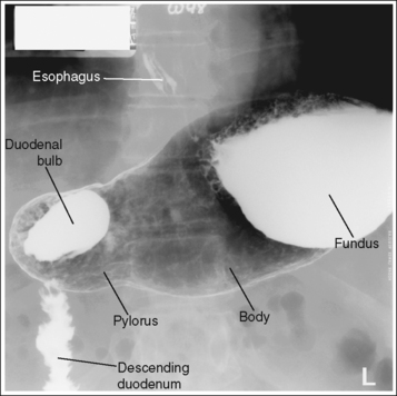
Stomach and Duodenum: Posteroanterior Oblique Projection (Right Anterior Oblique Position)
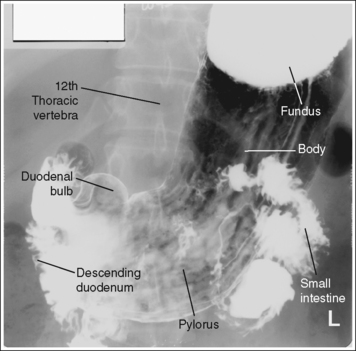
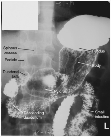
Stomach and Duodenum: Posteroanterior Projection
Stomach and Duodenum: Lateral Projection (Right Lateral Position)
Stomach and Duodenum: Anteroposterior Oblique Projection (Left Posterior Oblique Position)
Stomach and Duodenum: Anteroposterior Projection
Small Intestine: Posteroanterior Projection
Large Intestine: Posteroanterior or Anteroposterior Projection
Large Intestine (Rectum): Lateral Projection
Large Intestine: Anteroposterior or Posteroanterior Projection (Lateral Decubitus Position)
Large Intestine: Posteroanterior Oblique Projection (Right Anterior Oblique Position)
Large Intestine: Posteroanterior Oblique Projection (Left Anterior Oblique Position)
Large Intestine: Posteroanterior Axial Projection or Posteroanterior Axial Oblique Projection (Right Anterior Oblique Position)
After completion of this chapter, you should be able to do the following:
• Identify the required anatomy on upper and lower gastrointestinal projections.
• Describe how to properly position the patient, image receptor (IR), and central ray for upper and lower gastrointestinal projections.
• State how to properly mark and display upper and lower gastrointestinal projections.
• Explain the patient preparation procedure used before upper and lower gastrointestinal examinations to prevent residual debris and fluid from obscuring areas of interest.
• List the image analysis requirements for upper and lower gastrointestinal images with accurate positioning and state how to repostion the patient when less than optimal projections are produced.
• Describe the differences in size, shape, and position of the stomach and abdominal cavity placement of the small and large intestinal structures among the different types of habitus.
• Define the difference in the barium suspension that is ingested for upper and for lower gastrointestinal projections.
• State how a woman who has had one breast removed may have to be positioned at a greater object–image receptor distance (OID) for PA projections.
• Describe the differences in the appearance of the stomach on projections of patients with different types of body habitus.
• State where the barium and air will be situated for the different upper and lower gastrointestinal double-contrast projections.
• Explain why the small intestine is imaged at set time intervals for a small intestine study.
PREPARATION PROCEDURES
• Esophagram preparation. No preparation procedures are required when the esophagus is imaged, but if an esophagus and stomach examination is being performed, the stomach and duodenum preparation is to be followed.
• Stomach and duodenum preparation. Adequate preparation of the upper gastrointestinal (GI) system eliminates residual stomach debris, which may obscure abnormalities, and prevents excessive fluid from accumulating in the stomach, which could dilute the barium suspension enough to interfere with optimal mucosal coating (see Image 5). The preparation procedure for the upper GI system includes NPO (nothing orally) after midnight or at least 8 hours before the examination, and avoidance of gum and tobacco products before the procedure.
• Small intestine preparation. Optimal preparation of the small intestine for a small bowel study is obtained through a patient preparation procedure that includes a low-residue diet for 1 to 2 days before the examination, NPO after midnight and until the examination, and avoidance of gum and tobacco products before the examination (these are thought to increase salivation and gastric secretions).
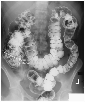
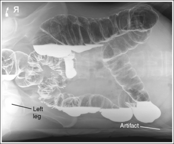
• Large intestine preparation. Adequate cleansing of the large intestine for a barium enema is obtained through a patient preparation procedure including a low-residue diet for 2 to 3 days before the examination, followed by a clear liquid diet 1 day before the examination, laxatives the afternoon before the examination, and a suppository or cleansing enema the morning of the examination. Remaining fecal material may obscure the mucosal surfaces and, when barium-coated, may mimic polyps and small tumors; remaining residual fluid causes dilution of the barium suspension, resulting in poor mucosal coating and coating artifacts (see Image 11).
On arrival in the fluoroscopic department, the patient should be queried to determine whether proper preparation instructions were given and followed. Adequate preparation can be assumed if the patient's last bowel movement lacked solid fecal material.
IMAGE ANALYSIS CRITERIA
The following image analysis criteria are used for all adult and pediatric digestive system images and should be considered when completing the analysis for each projection presented in this chapter (Box 12-1).
• Visibility of Digestive System Details. An optimal kilovoltage peak (kVp) technique, as shown in Table 12-1, sufficiently penetrates the barium-coated mucosal surface and provides the contrast needed to distinguish the mucosal patterns. Use a grid to reduce the scatter radiation that reaches the IR, thereby reducing fog, increasing the visibility of the recorded details, and providing a higher contrast image. To obtain optimal density, set a milliampere-seconds (mAs) level manually based on the patient's abdominal thickness or choose the appropriate automatic exposure control (AEC). For double-contrast examinations, using the AEC may be contraindicated because choosing the cell beneath the barium pool may result in overexposure of the area containing the air contrast (see Image 6).
TABLE 12-1
Digestive System Technical Data
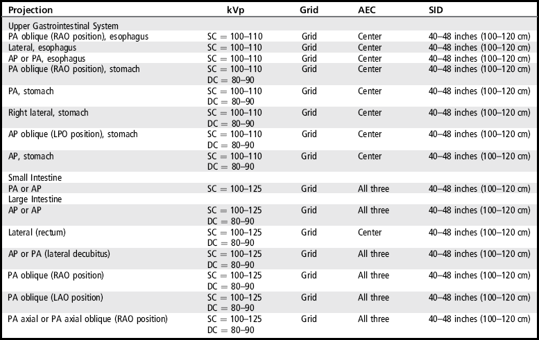
AEC, Automatic exposure control; AP, anteroposterior; DC, double contrast; kVp, kilovoltage peak; LPO, left posterior oblique; PA, posteroanterior; RAO, right anterior oblique; SC, single contrast; SID, source–image receptor distance.
• Pendulous breasts. Pendulous breasts may overlap and prevent clear visualization of the colic flexures unless they are shifted superiorly and laterally. Such movement also prevents excessive radiation exposure to the breasts.
• Exposure times. Short exposure times are needed when imaging the digestive system to control the image blur that may result from peristaltic activity within the system. Peristalsis is the contraction and relaxation movement of the smooth muscles in the walls of the digestive system that mixes food and secretions and moves the materials through the system. Peristaltic activity of the stomach and large or small intestine can be identified on an image by sharp bony cortices and blurry gastric and intestinal gases or barium (see Image 9).
The required upper and lower intestinal structures are included on the image. Adjustments in patient positioning, central ray centering, and IR size and direction are made to accommodate the patient's habitus.
• Body habitus. The body habitus determines the size, shape, and position of the stomach and the abdominal cavity placement of the large intestine. Being familiar with these differences will help the technologist adjust the central ray centering and IR placement for optimal demonstration of the required digestive structures.
Hypersthenic. The hypersthenic patient's abdomen is broad and deep from anterior to posterior. The stomach is positioned high in the abdomen and lies transversely at the level of the T9 to T12, with the duodenal bulb at the level of T11 to T12. The colic flexures and transverse colon tend to be positioned high in the abdomen (Figure 12-1). Using the sthenic patient as the reference point, this habitus will require a more superior and medial central ray centering and IR placement for AP and PA projections, a more superior and anterior central ray centering and IR placement for the lateral position of the stomach, and two crosswise IRs to include the entire large intestine for barium enema projections.
Asthenic. The asthenic patient's abdomen is narrow; the stomach is positioned low in the abdomen and runs vertically along the left side of the vertebral column, typically extending from T11 to L5, with the duodenal bulb at the level of L3 to L4. The small and large intestinal structures tend to be positioned low in the abdomen (Figure 12-2). Using the sthenic patient as the reference point, this habitus will require lower and more lateral centering of the central ray for stomach projections.
Sthenic. The sthenic habitus is the most common. The abdomen is less broad than the hypersthenic habitus, yet not as narrow as the asthenic. The stomach also rests at a position between the hypersthenic and asthenic habitus and typically extends from T10 to L2, with the duodenal bulb at the level of L1 to L2. The small and large intestinal structures tend to be centered in the abdomen (Figure 12-3).

The image was taken on full suspended expiration. The diaphragm dome is located superior to the ninth posterior ribs.
• From full inspiration to expiration the diaphragm position moves from an inferior to a superior position. This movement also changes the pressure placed on the abdominal structures. On full expiration the right side of the diaphragm dome is at the same transverse level as the eighth thoracic vertebrae, whereas on inspiration it may be found at the same transverse level as the ninth or tenth posterior rib. Exposing upper GI and small and large intestine projections on full expiration allows increased abdominal space for the structures to be demonstrated without segment overlapping and foreshortening (see Image 7).
ESOPHAGRAM: UPPER GASTROINTESTINAL SYSTEM
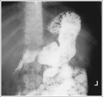
The esophagus is filled with barium, demonstrating its contour.
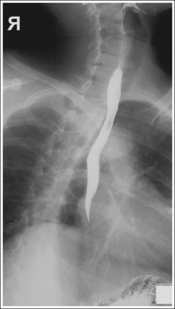
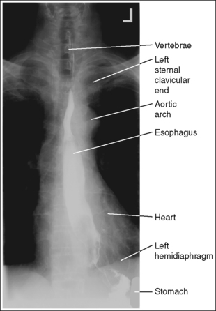
• Contrast. The goal of the esophagram is to demonstrate the workings and appearance of the pharynx and esophagus. This is accomplished through the fluoroscopic procedure and overhead projections that are obtained in an esophagram. Barium is used to demonstrate the pharynx and esophagus during this examination. A 30% to 50% weight or volume barium suspension is ingested continuously during the exposure, or two to three spoonfuls with toothpaste consistency; thick barium is ingested before exposing the esophagus, filling it with barium. The patient may also be asked to swallow cotton balls soaked in thin barium, barium-filled gelatin capsules, barium tablets, or marshmallows when a radiolucent foreign body or stricture is suspected. Adequate filling of the esophagus has occurred when the entire column is filled with barium. Only aspects of the esophagus that are filled with barium will be adequately demonstrated (see Images 1 and 3).
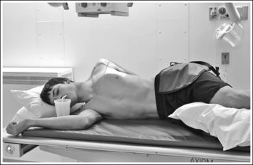
For the overhead projections, place a cup full of barium in the patient's hand and place the straw in the patient's mouth so that the patient can ingest barium during the exposure, or ask the patient to swallow two spoonfuls of thick barium and then give a third spoonful that is swallowed immediately before the exposure.
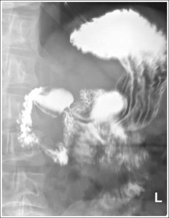
ESOPHAGRAM: POSTEROANTERIOR OBLIQUE PROJECTION (RIGHT ANTERIOR OBLIQUE POSITION)
See Figure 12-4 and Box 12-2.
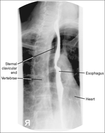
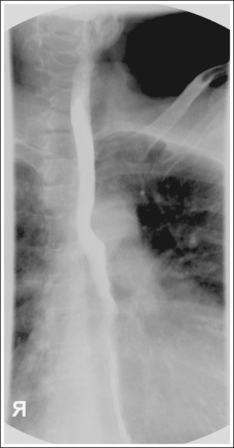
The barium-filled esophagus is demonstrated between the vertebrae and heart shadow, and approximately 0.5 inch (1.25 cm) of the right sternal (medial) clavicular end is demonstrated to the left of the vertebrae.
• A PA oblique esophagram projection (right anterior oblique [RAO]) is obtained by placing the patient prone on the imaging table and then rotating the torso toward the right side until the midcoronal plane is at a 35- to 40-degree angle with the imaging table (Figure 12-5). The patient's left elbow and knee may be flexed and used to support the body rotation.
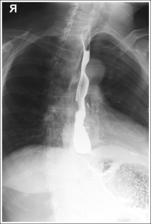
• Inaccurate patient rotation. If less than the desired 35 to 40 degrees of obliquity is obtained on a PA oblique esophagram projection, the vertebrae will be superimposed over the esophagus and the right sternal clavicular end (see Image 2). If the patient is rotated more than 40 degrees, more than 0.5 inch (1.25 cm) of the right sternal clavicular end will be demonstrated to the left of the vertebrae.
The midesophagus, at the level of T5 to T6, is at the center of the exposure field. The entire esophagus is included within the collimated field.
• To place the midesophagus in the center of the exposure field, center a perpendicular central ray approximately 3 inches (7.5 cm) to the left of the spinous processes and 2 to 3 inches (5 to 7.5 cm) inferior to the jugular notch. Center the IR to the central ray.
• Open the longitudinally collimated field the full 17-inch (43-cm) IR length. Transverse collimation should be to a 6-inch (15-cm) field size.
• A 14- × 17-inch (35- × 43-cm) IR placed lengthwise should be adequate to include all the required anatomic structures.
Posteroanterior Oblique Esophagram Projection (RAO Position) Analysis
Correction
The patient should drink barium continuously during the exposure or should swallow two spoonfuls of thick barium and then be given a third spoonful that is swallowed immediately before the exposure.
ESOPHAGRAM: LATERAL PROJECTION
See Figure 12-6 and Box 12-3.
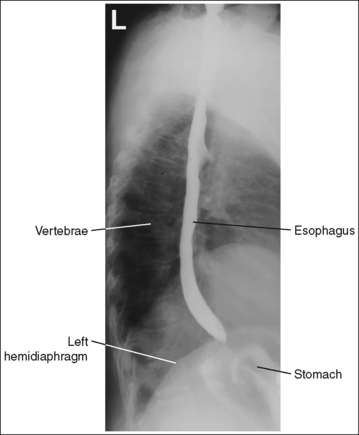
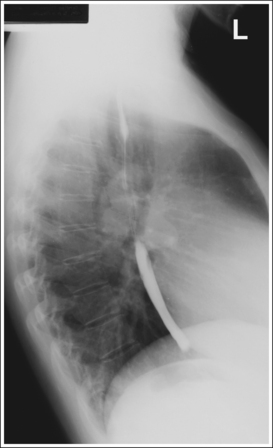
A barium-filled esophagus in a lateral projection is demonstrated. The esophagus is positioned anterior to the thoracic vertebrae, the posterior surfaces of each vertebral body are superimposed, and no more than 0.5 inch (1.25 cm) of space is demonstrated between the posterior ribs.
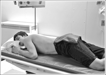
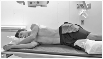
• To obtain a lateral esophagram projection, place the patient on the imaging table in a lateral recumbent position. Whether the patient is lying on the right or left side is not significant (Figure 12-7). Flex the patient's knees and hips for support, and position a pillow or sponge between the knees. The pillow or sponge should be thick enough to prevent the side of the pelvis situated farther from the IR from rotating anteriorly but not so thick as to cause posterior rotation. To avoid vertebral rotation, align the shoulders, posterior ribs, and posterior pelvis perpendicular to the imaging table and IR by resting an extended flat palm against each, respectively, and then adjusting patient rotation until the hand is positioned perpendicular to the IR.
• Detecting thorax rotation. Rotation can be detected on a lateral esophagram projection by evaluating superimposition of the right and left posterior surfaces of the vertebral bodies and superimposition of the posterior ribs. Because the two sides of the thorax and vertebrae are mirror images, it is very difficult to determine from a rotated lateral esophagram projection which side of the patient was rotated anteriorly and which posteriorly. If the patient was only slightly rotated, one way of determining which way the patient was rotated is to evaluate the amount of posterior rib superimposition. If the patient's elevated side was rotated posteriorly, the posterior ribs demonstrate more than 0.5 inch (1.25 cm) of space between them (see Chapter 8, Image 40). If the patient's elevated side was rotated anteriorly, the posterior ribs are superimposed on slight rotation (see Chapter 8, Image 41) and demonstrate greater separation as rotation of the patient increases.
No superimposition of shoulders or humeri over the esophagus is present.
• Humeral and shoulder positioning. Placing the humeri anteriorly at a 90-degree angle with the torso or separating the shoulders by positioning the arm and shoulder closer to the imaging table slightly forward and the arm and shoulder farther away from the imaging table back, while maintaining a lateral thorax (Figure 12-8), prevents the shoulders and humeri from being superimposed over the esophagus.
The midesophagus, at the level of T5 to T6, is at the center of the exposure field. The entire esophagus is included within the collimated field.
• Center a perpendicular central ray to the midcoronal plane at a level 2 to 3 inches (5 to 7.5 cm) inferior to the jugular notch to center the midesophagus at the center of the exposure field. Center the IR to the central ray.
• Open the longitudinally collimated field the full 17-inch (43-cm) IR length. Transverse collimation should be to a 6-inch (15-cm) field size.
• A 14- × 17-inch (35- × 43-cm) IR placed lengthwise should be adequate to include all the required anatomic structures.
ESOPHAGRAM: POSTEROANTERIOR PROJECTION
See Figure 12-9 and Box 12-4.
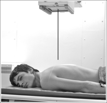
• To obtain a PA esophagus projection, place the patient prone on the imaging table. Position the shoulders and anterior superior iliac spines (ASISs) at equal distances from the imaging table to prevent rotation, and draw the patient's arms away from the abdominal area to prevent them from being superimposed over the abdominal region (Figure 12-10). Special attention should be given to female patients who have had one breast removed. The side of the patient on which the breast was removed may need to be placed at a greater OID than the opposite side to prevent rotation.
• Detecting rotation. Rotation is readily detected on a PA esophagus projection by evaluating the position of the esophagus with respect to the vertebrae and the distances from the vertebral column to the sternal clavicular ends. On a nonrotated esophagus projection, the vertebrae and esophagus are superimposed and the distances from the vertebrae to the sternal clavicular ends are equal on both sides. On a rotated PA projection, the side of the vertebrae toward which the esophagus is rotated and the sternal clavicular end that demonstrates less vertebral column superimposition represents the side of the chest positioned farther from the IR (see Image 4).
The midesophagus, at the level of T5 to T6, is at the center of the exposure field. The entire esophagus is included within the collimated field.
• Center a perpendicular central ray to the midsagittal plane at a level 2 to 3 inches (5 to 7.5 cm) inferior to the jugular notch for the AP projection and at the level of T5 to T6 (2 to 3 inches superior to the inferior scapular angle) for the PA projection to center the midesophagus at the center of the exposure field. Center the IR to the central ray.
• Open the longitudinally collimated field the full 17-inch (43-cm) IR length. Transverse collimation should be to a 6-inch (15-cm) field size.
• A 14- × 17-inch (35- × 43-cm) IR placed lengthwise should be adequate to include all the required anatomic structures.
STOMACH AND DUODENUM
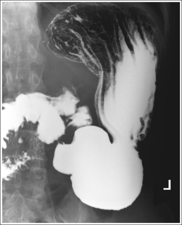
Single contrast: The stomach and duodenum is barium-filled, demonstrating the contour of the stomach and lumen.
• The single-contrast PA stomach and duodenum projection demonstrates barium-filled organs with normally present gas. The primary goal of a single-contrast upper GI study is to demonstrate abnormalities of the stomach and lumen contour. A 30% to 50% weight or volume barium suspension is typically used for this study.
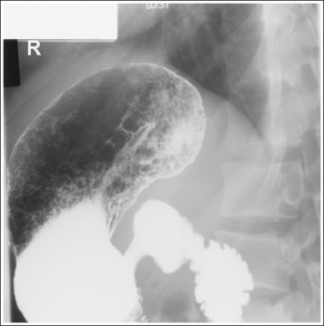
Double contrast: The stomach and duodenum demonstrate adequate distention and mucosal covering. The rugae (longitudinal gastric folds) are smoothed out, the gastric surface pattern is demonstrated, and a thin, uniform barium line is visible along the contour of the stomach.
• The goal of a double-contrast study is to visualize abnormalities in the mucosal details and contour and lumen of the stomach and duodenum.
Negative (radiolucent) contrast is most commonly obtained by having the patient swallow effervescent granules, powder, or tablets that rapidly release 300 to 400 mL of carbon dioxide on contact with the fluid in the stomach. The carbon dioxide causes gastric distention and smoothing of the rugae.
Positive (radiopaque) contrast is obtained by having the patient drink a high-density (up to 250% weight or volume) barium suspension. The barium provides the thin coating that covers the mucosal surface. To obtain adequate mucosal coating of the area, the barium is washed over the gastric surface by having the patient turn 360 degrees and then positioning the patient so that the barium pool will be placed away from the area of interest. Because the barium will slowly flow toward the lowest level after coating, the patient should be rotated between projections or the sequence of projections should be taken to optimize coating of the area of interest to maintain an optimal mucosal covering. Table 12-2 indicates where the barium will pool and which aspect of the upper GI tract is best demonstrated in the most commonly obtained stomach and duodenum projections.
TABLE 12-2
Double-Contrast Filling of Upper Gastrointestinal System
| Stomach | Barium-Filled Structures | Air-Filled Structures |
| PA oblique (RAO position) | Pylorus, duodenum | Fundus |
| PA projection | Pylorus, duodenum | Fundus |
| Right lateral projection | Pylorus, duodenum, body | Fundus |
| AP oblique (LPO position) | Fundus | Pylorus, duodenum |
| AP projection | Fundus | Pylorus, duodenum, body |
Failure to obtain good mucosal coating may result in missed or simulated lesions. The quality of the mucosal coating depends on the properties of the barium suspension, the volume of barium and gas, the frequency of washing, and the amount of fluid or secretions and viscosity of mucus in the stomach. Although proper double-contrast filling is primarily the fluoroscopist's responsibility, the technologist's scope of practice does play a part in some of the causes of poor coating, such as using the wrong type of barium, improperly preparing the barium suspension, or performing poor lower intestine preparation. A thorough mixing of the barium suspension is required before the patient ingests the material.
STOMACH AND DUODENUM: POSTEROANTERIOR OBLIQUE PROJECTION (RIGHT ANTERIOR OBLIQUE POSITION)
See Figures 12-11, 12-12, and 12-13 and Box 12-5.
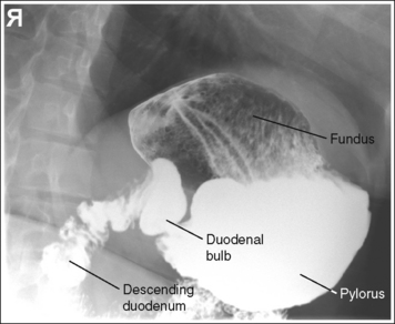
FIGURE 12-11 Hypersthenic PA oblique spot stomach and duodenal projection (RAO position) with accurate positioning.
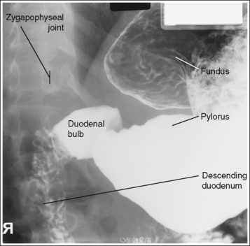
FIGURE 12-12 Sthenic PA oblique spot stomach and duodenal projection (RAO position) with accurate positioning.
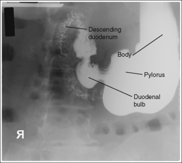
FIGURE 12-13 Asthenic PA oblique spot stomach and duodenal projection (RAO position) with accurate positioning.
Contrast distribution: Air contrast is demonstrated in the fundus, and barium is visible in the pylorus, duodenal bulb, and descending duodenum. An optimal PA oblique stomach projection has been obtained when the lumbar vertebrae demonstrate an oblique position, with the degree of obliquity adequate for the body habitus, and when the correct aspect of the stomach, as defined by the body habitus, is in profile.
• Hypersthenic habitus. The patient has been rotated 70 degrees, as identified by the demonstration of the left lumbar zygapophyseal joints in the posterior third of the vertebral bodies. The duodenal bulb and descending duodenum are in profile, and the long axis of the stomach demonstrates foreshortening with a closed lesser curvature (see Figure 12-11).
• Sthenic habitus. The patient has been rotated approximately 45 degrees, as identified by the demonstration of the left lumbar zygapophyseal joints at the midline of the vertebral bodies. The duodenal bulb and descending duodenum are in profile, and the long axis of the stomach is partially foreshortened, with a partially closed lesser curvature (see Figure 12-12).
• Asthenic habitus. The patient has been rotated approximately 40 degrees, as identified by the demonstration of the left lumbar zygapophyseal joints in the anterior third of the vertebral bodies. The duodenal bulb and descending duodenum are in profile, the long axis of the stomach is demonstrated without foreshortening, and the lesser curvature is open (see Figure 12-13).
• A PA oblique stomach projection (RAO position) is obtained by placing the patient prone on the imaging table and then rotating the torso toward the right side until the midcoronal plane is at a 40- to 70-degree angle with the imaging table (Figure 12-14). The patient's left elbow and knee may be flexed and used to support the body rotation. In general, hypersthenic habitus patients require approximately 70 degrees of obliquity, and the asthenic habitus approximately 40 degrees. The difference in the degree of obliquity for the body habitus is a result of the difference in the amount of superimposition of the pylorus and duodenal bulb that exists among patients with different habitus.
The pylorus is centered within the exposure field. The stomach and duodenal loop are included within the collimated field.
• To place the pylorus in the center of the exposure field, center a perpendicular central ray halfway between the vertebrae and lateral rib border of the elevated side at a level 1 to 2 inches (2.5 to 5 cm) superior to the inferior rib margin for the sthenic habitus. Center the central ray at a level 2 inches (5 cm) superior to the sthenic patient centering for the hypersthenic habitus, and at a level 2 inches inferior for the asthenic habitus. Center the IR to the central ray.
• Open the longitudinally collimated field the full 14-inch (35-cm) IR length. Transverse collimation should be to the vertebrae and lateral rib border.
• An 11- × 14-inch (28- ×35-cm) IR placed lengthwise should be adequate to include all the required anatomic structures.
STOMACH AND DUODENUM: POSTEROANTERIOR PROJECTION
See Figures 12-15, 12-16, and 12-17 and Box 12-6.
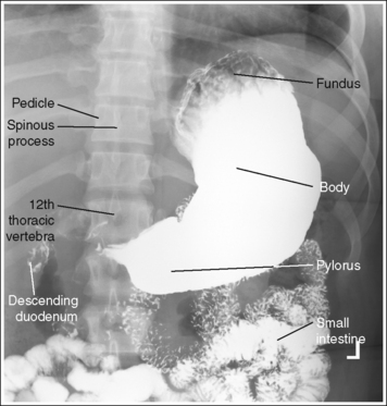
Contrast distribution: Air contrast is demonstrated in the fundus, and barium is visible in the body and pylorus. An optimal PA stomach and duodenum projection has been obtained when the spinous processes are aligned with the midline of the vertebral bodies, the distances from the pedicles to the spinous processes are the same on both sides, and the correct aspect of the stomach, as defined by the body habitus, is in profile.
• Hypersthenic habitus. The stomach is aligned almost horizontally, with the duodenal bulb at the level of T11 to T12. The lesser and greater curvatures are demonstrated almost on end, with the greater curvature being more anteriorly situated and the esophagogastric junction almost on end (see Figure 12-15).
• Sthenic habitus. The stomach is aligned almost vertically, with the duodenal bulb at the level of L1 to L2. The stomach is somewhat J-shaped and its long axis is partially foreshortened. The lesser and greater curvatures, esophagogastric junction, pylorus, and duodenal bulb are in partial profile (see Figure 12-16).
• Asthenic habitus. The stomach is aligned vertically, with the duodenal bulb at the level of L3 to L4. The stomach is J-shaped and its long axis is demonstrated without foreshortening. The lesser and greater curvatures, esophagogastric junction, pylorus, and duodenal bulb are in profile (see Figure 12-17).
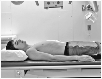
• To obtain a PA stomach projection, place the patient prone on the imaging table. Position the shoulders and pelvic ala at equal distances from the imaging table to prevent rotation and draw the patient's arms away from the abdominal area to prevent them from being superimposed over the abdominal region (Figure 12-18).
• Detecting abdominal rotation. Rotation is effectively detected on a PA stomach projection by comparing the distance from the pedicles to the spinous processes on both sides. The side demonstrating the greater distance from the pedicles to the spinous processes is the side positioned farther from the IR.
The pylorus is centered within the exposure field. The stomach and descending duodenum are included within the collimated field.
• To position the pylorus in the center of the collimated field for the sthenic habitus, center a perpendicular central ray halfway between the vertebrae and left lateral rib border at a point approximately 1 to 2 inches (2.5 to 5 cm) superior to the lower rib margin. For the hypersthenic habitus, direct the central ray just to the left of the vertebrae at a level 2 inches (5 cm) superior to the sthenic habitus centering point. For the asthenic habitus, direct the central ray 2 inches inferior to the sthenic habitus centering point. Center the IR to the central ray.
• Open the longitudinally collimated field the full 14-inch (35-cm) IR length. Transverse collimation should be to the vertebrae and lateral rib border.
• An 11- × 14-inch (28- × 35-cm) IR placed lengthwise should be adequate to include all the required anatomic structures.
Posteroanterior Stomach and Duodenum Projection Analysis
The stomach demonstrates a blotchy appearance within the barium. The stomach contains residual food particles. The patient did not follow adequate preparation procedure.
Correction
The preparation procedure for the stomach includes NPO after midnight or for at least 8 hours before the examination and avoidance of gum and tobacco products before the procedure.
Analysis
The air-contrast fundus is overexposed, preventing demonstration of abnormalities. Either the mAs was too high or the AEC was positioned beneath the barium-filled body and pylorus.
Correction
Decrease the mAs enough to demonstrate the fundus or manually set the mAs instead of using the AEC.
Analysis
The examination was obtained after full inspiration, compressing and foreshortening the stomach. Compare this projection with the projections obtained on expiration in Figures 12-3 and 12-16.
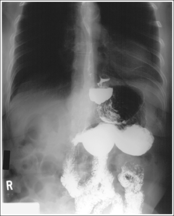
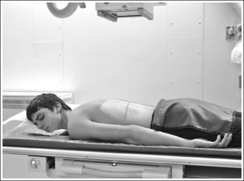
STOMACH AND DUODENUM: LATERAL PROJECTION (RIGHT LATERAL POSITION)
See Figures 12-19, 12-20, and 12-21 and Box 12-7.
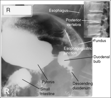
FIGURE 12-19 Hypersthenic lateral spot stomach and duodenal projection (right lateral position) with accurate positioning.
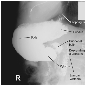
FIGURE 12-20 Sthenic lateral stomach and duodenal projection (right lateral position) with accurate positioning.
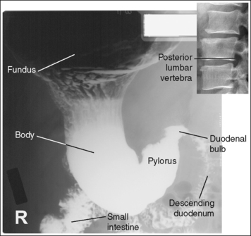
FIGURE 12-21 Asthenic lateral spot stomach and duodenal projection (right lateral position) with accurate positioning.
Contrast distribution: Air contrast is demonstrated in the fundus, and barium is visible in the pylorus, duodenum bulb, and descending duodenum.
An optimal right lateral stomach and duodenal projection has been obtained when the thoracic and lumbar vertebrae demonstrate a lateral projection, with the superimposed posterior surfaces of each vertebral body, when the stomach, duodenal bulb, and descending duodenum are anterior to the vertebrae, demonstrating the retrogastric space, and when the correct aspect of the stomach, as defined by the body habitus, is in profile.
• Hypersthenic habitus. The duodenal bulb and descending duodenum are in profile, and the long axis of the stomach demonstrates foreshortening with a closed lesser curvature (see Figure 12-19).
• Sthenic habitus. The duodenal bulb and descending duodenum are in profile, and the long axis of the stomach is partially foreshortened with a partially closed lesser curvature (see Figure 12-20).
• Asthenic habitus. The duodenal bulb and descending duodenum are in profile, the long axis of the stomach is demonstrated without foreshortening, and the lesser curvature is open (see Figure 12-21).
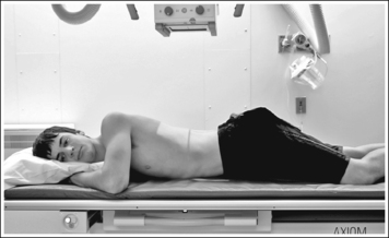
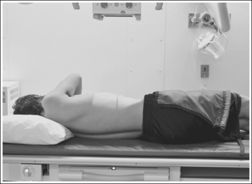
• To obtain a lateral stomach projection, place the patient on the imaging table in a right lateral recumbent position. Flex the patient's knees and hips for support (Figure 12-22). To avoid rotation, align the shoulders, posterior ribs, and posterior pelvis perpendicular to the imaging table and IR. This is accomplished by resting your extended flat palm against each structure, individually, and then adjusting the patient's rotation until your hand is positioned perpendicular to the imaging table.
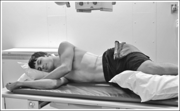
FIGURE 12-22 Proper patient positioning for lateral stomach and duodenal projection (right lateral position).
• Detecting rotation. Rotation can be detected on a lateral stomach and duodenal projection by evaluating the superimposition of the right and left posterior surfaces of the vertebral bodies. On a nonrotated lateral stomach and duodenal projection, these posterior surfaces are superimposed, appearing as one. On rotation, these posterior surfaces are not superimposed but are demonstrated one anterior to the other (see Image 8).
The pylorus is centered within the exposure field. The stomach and duodenal loop are included within the collimated field.
• To place the pylorus in the center of the exposure field, center a perpendicular central ray halfway between the midcoronal plane and anterior abdomen at the level of the inferior rib margin for the sthenic habitus. For the hypersthenic habitus, direct the central ray at a level 2 inches (5 cm) superior to the sthenic habitus centering point. For the asthenic habitus, direct the central ray 2 inches inferior to the sthenic habitus centering point. Center the IR to the central ray.
• Open the longitudinally collimated field the full 14-inch (35-cm) IR length. Transverse collimation should be to the vertebrae and anterior abdomen border.
• An 11- × 14-inch (28- × 35-cm) IR placed lengthwise should be adequate to include all the required anatomic structures.
STOMACH AND DUODENUM: ANTEROPOSTERIOR OBLIQUE PROJECTION (LEFT POSTERIOR OBLIQUE POSITION)
See Figures 12-23, 12-24, and 12-25 and Box 12-8.
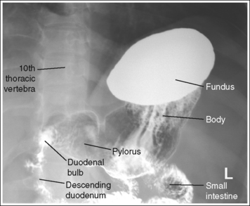
FIGURE 12-23 Hypersthenic AP oblique spot stomach and duodenal projection (LPO position) with accurate positioning.
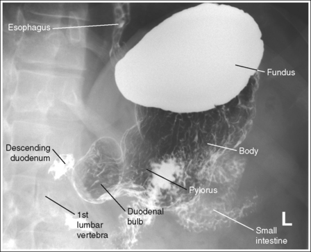
FIGURE 12-24 Sthenic AP oblique spot stomach and duodenal projection (LPO position) with accurate positioning.
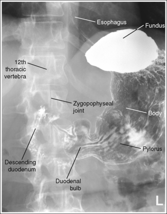
FIGURE 12-25 Asthenic AP oblique spot stomach and duodenal projection (LPO position) with accurate positioning.
Contrast distribution: Air contrast is demonstrated in the pylorus, duodenal bulb, and descending duodenum, and barium is visible in the fundus.
An optimal AP oblique stomach and duodenal projection (LPO position) has been obtained when the lumbar vertebrae demonstrate an oblique position with the degree of obliquity adequate for the body habitus and when the correct aspect of the stomach, as defined by the body habitus, is in profile.
• Hypersthenic habitus. The patient has been rotated 60 degrees, as identified by the demonstration of the left lumbar zygapophyseal joints in the posterior third of the vertebral bodies. The duodenal bulb and descending duodenum are in profile, and the pylorus is superimposed over the vertebrae (see Figure 12-23).
• Sthenic habitus. The patient has been rotated 45 degrees, as identified by the demonstration of the left lumbar zygapophyseal joints at the midline of the vertebral bodies. The duodenal bulb and descending duodenum are in profile, and the vertebrae are demonstrated with little if any pyloric superimposition (see Figure 12-24).
• Asthenic habitus. The patient has been rotated 30 degrees, as identified by the demonstration of the left lumbar zygapophyseal joints in the anterior third of the vertebral bodies. The duodenal bulb and descending duodenum are in profile, and the vertebrae are demonstrated with little if any pyloric superimposition (see Figure 12-25).
• An AP oblique stomach and duodenal projection (left posterior oblique [LPO]) is obtained by placing the patient supine on the imaging table and then rotating the patient toward the left side until the midcoronal plane is at a 30- to 60-degree angle with the imaging table (Figure 12-26). The patient's right arm is drawn across the chest, the hand grasps the table edge, and the right knee is flexed for support. A radiolucent sponge positioned beneath the right surface may also help the patient maintain the correct obliquity. Rotate the patient with a hypersthenic habitus approximately 60 degrees and the patient with the asthenic habitus approximately 30 degrees.
The pylorus is centered within the exposure field. The stomach and duodenal loop are included within the collimated field.
• To position the pylorus in the center of the exposure field, center a perpendicular central ray halfway between the vertebrae and left abdominal margin at a level midway between the xiphoid process and inferior rib margin for the sthenic habitus. Center the central ray at a level 2 inches (5 cm) superior to the sthenic habitus central ray centering for the hypersthenic habitus and 2 inches inferior for the asthenic habitus. Center the IR to the central ray.
• Open the longitudinally collimated field the full 14-inch (35-cm) IR length. Transverse collimation should be to the vertebrae and lateral rib border.
• An 11- × 14-inch (28- × 35-cm) IR placed lengthwise should be adequate to include all the required anatomic structures.
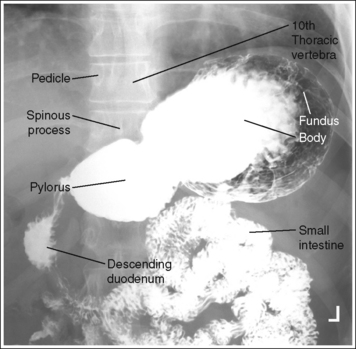
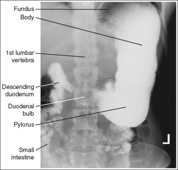
STOMACH AND DUODENUM: ANTEROPOSTERIOR PROJECTION
See Figures 12-27, 12-28, and 12-29 and Box 12-9.
Contrast distribution: Air contrast is demonstrated in the pylorus, duodenal bulb, and descending duodenum, and barium is visible in the fundus.
An optimal AP stomach projection has been obtained when the spinous processes are aligned with the midline of the vertebral bodies, the distances from the pedicles to the spinous processes are the same on both sides, and the correct aspect of the stomach, as defined by the body habitus, is in profile.
• Hypersthenic habitus. The stomach is aligned almost horizontally, with the duodenal bulb at the level of T11 to T12. The lesser and greater curvatures are demonstrated almost on end, with the greater curvature being more anteriorly situated, and the esophagogastric junction is almost on end (see Figure 12-27).
• Sthenic habitus. The stomach is aligned almost vertically, with the duodenal bulb at the level of L1 to L2. The stomach is somewhat J-shaped, and its long axis is partially foreshortened. The lesser and greater curvatures, esophagogastric junction, pylorus, and duodenal bulb are in partial profile (see Figure 12-28).
• Asthenic habitus. The stomach is aligned vertically, with the duodenal bulb at the level of L3 to L4. The stomach is J-shaped, its long axis is demonstrated without foreshortening, and the lesser and greater curvatures, esophagogastric junction, pylorus, and duodenal bulb are demonstrated in profile (see Figure 12-29).
• To obtain an AP stomach and duodenal projection, place the patient supine on the imaging table. Position the shoulders and ASISs at equal distances from the imaging table to prevent rotation, and draw the patient's arms away from the abdominal area to prevent them from being superimposed over the abdominal region (Figure 12-30).
• Detecting abdominal rotation. Rotation is effectively detected on an AP stomach and duodenal projection by comparing the distance from the pedicles to the spinous processes on each side. The side demonstrating the greater distance from the pedicle to the spinous processes is the side positioned closer to the IR.
The pylorus is centered within the exposure field. The stomach and duodenal loop are included within the collimated field.
• To position the pylorus in the center of the exposure field, center a perpendicular central ray halfway between the vertebrae and left abdominal margin at a level midway between the xiphoid process and inferior rib margin sthenic habitus. Center the central ray just medial to the left side of the vertebrae at a level 2 inches (5 cm) superior to the sthenic patient centering for the hypersthenic habitus and at a level 2 inches inferior for the asthenic habitus. Center the IR to the central ray.
• Open the longitudinally collimated field the full 14-inch (35-cm) IR length. Transverse collimation should be to the lateral rib border.
• An 11- × 14-inch (28- × 35-cm) IR placed lengthwise should be adequate to include all the required anatomic structures.
SMALL INTESTINE
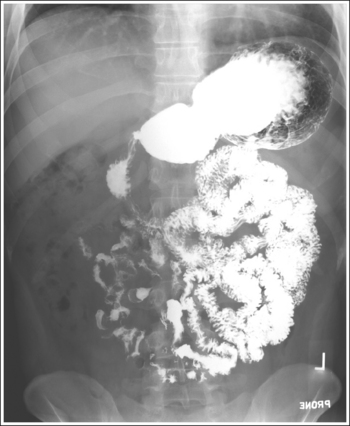
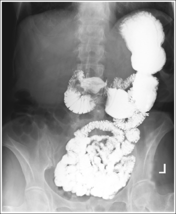
SMALL INTESTINE: POSTEROANTERIOR PROJECTION
See Figures 12-31, 12-32, 12-33 and Box 12-10.
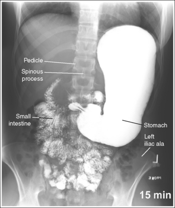
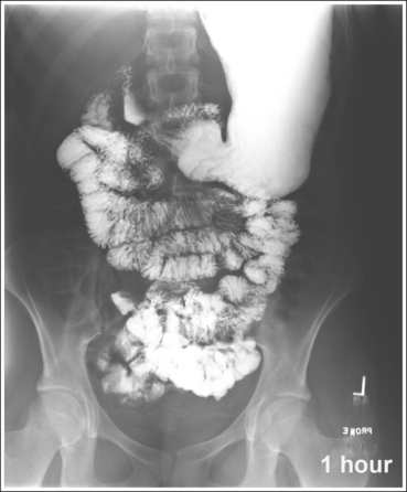
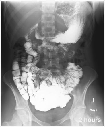
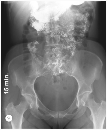
A marker indicating the amount of time that has elapsed since the patient ingested the contrast medium is included within the collimated field and is not superimposed over anatomic structures of interest.
• For studies of the small intestine, the patient drinks a large amount of barium; then the technologist obtains overhead projections of the stomach and small intestine at timed intervals as peristalsis moves the contrast from the stomach through the small intestine to the cecum. The timing begins when the patient ingests the contrast or as determined by the radiologist. Typically, the first prone overhead image is obtained at 15 minutes, then at 30 minutes, and then hourly until the barium is demonstrated in the cecum. The barium normally takes 2 to 3 hours to reach the cecum but may vary greatly from patient to patient. Each projection in the timed series must contain a time marker to indicate the amount of time that has passed since the contrast was ingested.
The abdomen demonstrates a PA projection. The spinous processes are aligned with the midline of the vertebral bodies, the distances from the pedicles to the spinous processes are the same on both sides, and the iliac alae are symmetrical.
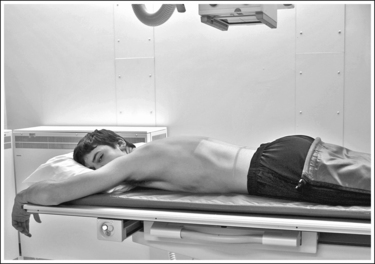
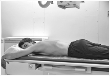
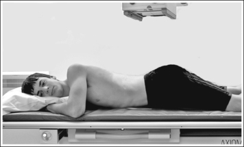
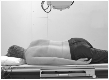
• To obtain a PA small intestine projection, place the patient prone on the imaging table. Position the shoulders and ASISs at equal distances from the imaging table to prevent rotation, and draw the patient's arms away from the abdominal area to prevent them from being superimposed over the abdominal region (Figure 12-34). The prone position is chosen to demonstrate the small intestine because it will cause compression of the abdominal structures, increasing image quality.
• Detecting abdominal rotation. The upper and lower lumbar vertebrae can demonstrate rotation independently or simultaneously, depending on which section of the body is rotated. If the patient's thorax was rotated but the pelvis is not, the upper lumbar vertebrae and abdominal cavity demonstrate rotation. If the patient's pelvis was rotated but the thorax was not, the lower vertebrae and abdominal cavity demonstrate rotation. If the patient's thorax and pelvis were rotated simultaneously, the entire abdominal cavity demonstrates rotation. Rotation is effectively detected on a PA small intestine projection by comparing the distances from the pedicles to the spinous processes on both sides and the symmetry of the iliac alae. The side demonstrating the greater distance from the pedicles to the spinous processes and the wider iliac ala is the side positioned farther from the IR.
The small intestine is centered within the exposure field. The stomach and proximal aspects of the small intestine are included within the collimated field on projections taken early in the series, and the small intestine and cecum are included on projections taken later in the series.
• To include the stomach and small intestine on projections obtained earlier in the series, use a perpendicular central ray with the midsagittal plane at a level 2 inches (5 cm) superior to the iliac crest. To include the small intestine and cecum on projections obtained later in the series, direct the central ray to the midsagittal plane at the level of the iliac crest. Center the IR to the central ray (see Image 10).
• The longitudinal collimated field should remain fully open. Transversely collimate to within 0.5 inch (1.25 cm) of the patient's lateral skin line.
• IR size and direction. A 14- × 17-inch (35- × 43-cm) lengthwise IR should be adequate to include all the required anatomic structures on sthenic and asthenic patients, as long as the transverse abdominal measurement is less than 14 inches (35 cm).
Use two 14- × 17-inch (35- × 43-cm) crosswise IRs on hypersthenic patients and on other patients who have a transverse abdominal measurement of 14 inches (35 cm) or more to include all the necessary anatomic structures. Take the first projection with the central ray centered to the midsagittal plane at a level halfway between the symphysis pubis and ASIS. Position the bottom of the second IR so it includes 2 to 3 inches (5 to 7.5 cm) of the same transverse section of the peritoneal cavity imaged on the first projection to ensure that no middle peritoneal information has been excluded. It may be necessary to obtain only the superiorly positioned image for the initially obtained image, because the barium may not travel to the inferiorly situated small bowel so soon in the procedure.
LARGE INTESTINE
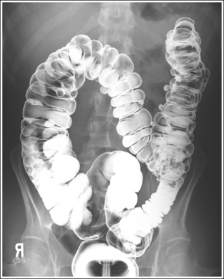
The large intestine demonstrates adequate distention and mucosal covering. The lumina are distended without mucosal folds, the mucosal surface demonstrates a thin coating of barium, and barium pooling is limited to one third of the intestinal diameter.
• Good double-contrast lower intestinal filling. Good gaseous distention is demonstrated when the bowel lumina are distended, eliminating the mucosal folds and allowing all parts of the barium-coated mucosal lining of the colon and any small intraluminal lesions to be visualized. Good lower intestinal barium coating has been obtained when the surface positioned farther from the IR on recumbent projections or superiorly on erect projections, also called the nondependent surface, demonstrates a thin layer of barium coating on the mucosal surface, and when the surface positioned closer to the IR on recumbent projections or inferiorly on erect projections, also called the dependent (decubitus) surface, demonstrates a thin layer of barium coating of the highest structures, with barium pooled in the lower crevices. The barium pools are used to wash away residual fecal material from the dependent surface, coat the mucosal surface, and fill any depressed lesions as the patient is rotated. Ideally, barium should fill one third of the large intestine diameter; overfilling or underfilling may result in obscured lesions or inadequate intestinal washing, respectively. See Table 12-3 to determine where barium pooling will occur on a lower intestine image. Pooling will occur in the anterior surface on prone projections, posterior surface on supine projections and, inferiorly, between the mucosal folds, on erect projections.
TABLE 12-3
Double-Contrast Filling of Large Intestinal Structures
| Large Intestine | Supine Position | Prone Position |
| Cecum | Air | Barium |
| Ascending colon | Barium | Air |
| Ascending limb right colic (hepatic) flexure | Barium | Air |
| Descending limb right colic (hepatic) flexure | Barium | Air |
| Transverse colon | Air | Barium |
| Ascending limb left colic (splenic) flexure | Air | Barium |
| Descending limb left colic (splenic) flexure | Barium | Air |
| Descending colon | Barium | Air |
| Sigmoid colon | Air | Barium |
| Rectum | Barium | Air |
• Poor double contrast. Poor gaseous distension results in pockets of large barium pools, compacted intestinal segments with tight mucosal folds. Poor mucosal coating is demonstrated by thin, irregular, or interrupted barium coating or excessive barium pooling. Poor coating may cause lesions to be easily missed. Although proper double-contrast filling is primarily the fluoroscopist's responsibility, the technologist's scope of practice may play a part in some of the causes for poor coating, such as using the wrong type of barium, improperly preparing the barium suspension, or performing poor lower intestinal preparation.
LARGE INTESTINE: POSTEROANTERIOR OR ANTEROPOSTERIOR PROJECTION
See Figures 12-35 and 12-36 and Box 12-11.
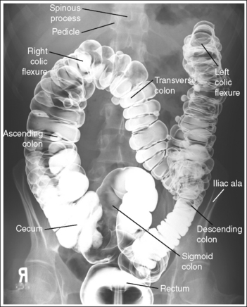
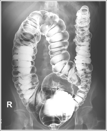
The abdomen is in a PA or AP projection. The spinous processes are aligned with the midline of the vertebral bodies, the distances from the pedicles to the spinous processes are the same on both sides, and the iliac ala are symmetrical. The ascending and descending limbs of the colic flexures demonstrate some degree of superimposition.
• To obtain a PA large intestine projection, place the patient prone on the imaging table. To obtain an AP large intestine projection, place the patient supine on the imaging table. Position the shoulders and ASISs at equal distances from the imaging table to prevent rotation, and draw the patient's arms away from the abdominal area to prevent them from being superimposed over the abdominal region (Figure 12-37).
• Detecting abdominal rotation. Rotation is effectively detected on a PA or AP lower intestine projection by comparing the distances from the pedicles to the spinous processes on both sides, the symmetry of the iliac ala, and the superimposition of the colic flexures.
PA projection. The side demonstrating the greater distance from the pedicles to the spinous processes, wider iliac ala, and colic flexure with greater ascending and descending limb superimposition is the side positioned farther from the IR (see Image 12).
AP projection. The side demonstrating the greater distance from the pedicle to the spinous processes, wider iliac ala, and colic flexure with the greater ascending and descending limb superimposition is the side positioned closer to the IR.
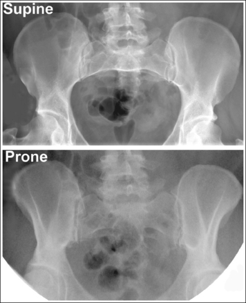
The beam divergence causes very different-appearing iliac alae on an image that is obtained in a supine versus a prone position. Figure 12-38 demonstrates the iliac alae of a supine and prone abdomen; note that the iliac alae in the image obtained with the patient supine are wider than with the patient prone. This information can be used to distinguish whether the image was taken with the patient in a supine or prone position. The narrow iliac ala of a prone projection should not be mistaken for narrowness caused by rotation.
The fourth lumbar vertebra is centered within the exposure field. The entire large intestine, including the left colic (splenic) flexure and rectum, is included within the collimated field.
• To position the fourth lumbar vertebra in the center of the exposure field, center a perpendicular central ray with the patient's midsagittal plane at the level of the iliac crest. Center the IR to the central ray. The longitudinal collimated field should remain fully open. Transversely collimate to within 0.5 inch (0.6 cm) of the patient's lateral skin line.
• IR size and direction. A 14-× 17-inch (35- × 43-cm) lengthwise IR should be adequate to include all the required anatomic structures on sthenic and asthenic patients as long as the transverse abdominal measurement is less than 14 inches (35 cm).
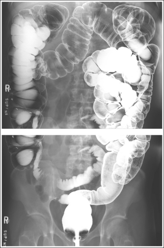
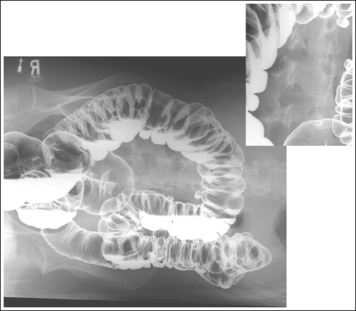
Use two 14- × 17-inch (35- × 43-cm) crosswise IRs on hypersthenic patients and on other patients who have a transverse abdominal measurement of 14 inches (35 cm) or more to include all the necessary anatomic structures (Figure 12-39; see Image 13). Take the first projection with the central ray centered to the midsagittal plane at a level halfway between the symphysis pubis and ASIS. Position the bottom of the second IR so that it includes 2 to 3 inches (5 to 7.5 cm) of the same transverse section of the peritoneal cavity imaged on the first projection to ensure that no middle peritoneal information has been excluded. The top of the IR should extend to the patient's xiphoid (which is at the level of the tenth thoracic vertebra) to make sure that the left colic (splenic) flexure is included.
Posteroanterior or Anteroposterior Large Intestine Projection Analysis
PA projection—remaining fecal material is visible in the cecum. Fecal material may obscure the mucosal surfaces and, when barium-coated, may mimic polyps and small tumors.
Analysis
PA projection—the right iliac ala is narrow, the left iliac ala is wide, the distance from the right pedicles to the spinous processes is narrower than the same distance on the left side, and the left colic (splenic) flexure demonstrates greater ascending and descending limb superimposition. The patient was rotated toward the right side.
Correction
Rotate the patient toward the left side until the shoulders and iliac alae are at equal distances to the imaging table.
LARGE INTESTINE (RECTUM): LATERAL PROJECTION
See Figure 12-40 and Box 12-12.
Scatter radiation is controlled.
• A grid and lead sheet are placed on the imaging table at the edge of the posteriorly collimated field to reduce the amount of scatter radiation that reaches the IR, providing higher contrast and better visibility of recorded details.
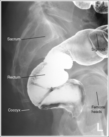
The rectum is in profile. The sacrum demonstrates a lateral projection. The median sacral crest is in profile, and the femoral heads are superimposed.
• To obtain a lateral sacral projection, place the patient on the imaging table in a lateral recumbent position. Whether the patient is lying on the right or left side is not significant, although the left side positioning is easier for the technologist.
Flex the patient's knees and hips for support, and position a pillow or sponge between the knees. The pillow or sponge should be thick enough to prevent the side of the pelvis situated farther from the IR from rotating anteriorly, without being so thick as to cause this side to rotate posteriorly (Figure 12-41).
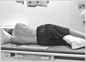
To avoid rectal and vertebral rotation, align the shoulders, posterior ribs, and posterior pelvis perpendicular to the imaging table and IR. This is accomplished by resting your extended flat palm against each structure individually and adjusting the patient's rotation until your hand is positioned perpendicular to the imaging table.
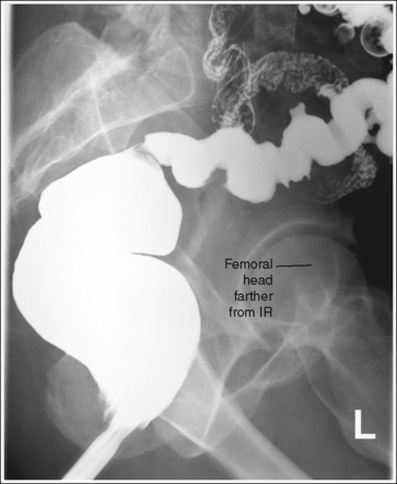
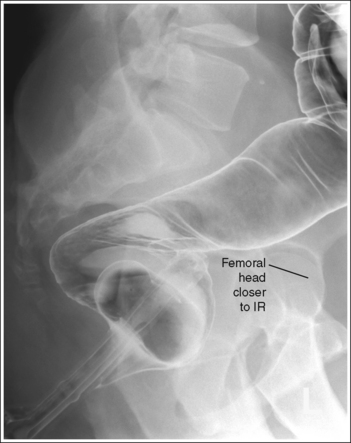
• Detecting rotation. Rotation can be detected on a lateral rectum projection by evaluating the degree of femoral head superimposition. On a nonrotated lateral rectal projection, the femoral heads are directly superimposed. On rotation, the femoral heads will move away from each other. When rotation has occurred, evaluate the placement of the femoral heads to determine the way in which the patient was rotated. The femoral head that demonstrates the greater magnification is the one situated farther from the IR (see Images 14 and 15).
The rectosigmoid region is at the center of the exposure field. The rectum, distal sigmoid, sacrum, and femoral heads are included within the collimated field.
• To place the rectosigmoid region in the center of the exposure field, center a perpendicular central ray to the midcoronal plane (between the ASIS and posterior sacrum) at the level of the ASIS. Center the IR to the central ray.
• Open the longitudinal and transverse collimation to the full IR field size.
• A 10- × 12-inch (24- × 30-cm) IR placed lengthwise should be adequate to include all the required anatomic structures.
Lateral Large Intestine (Rectum) Projection Analysis
A lateral position has not been obtained. The femoral heads are not superimposed; the right femoral head is rotated anterior to the left femoral head.
Correction
Rotate the right side of the patient posteriorly until the posterior pelvic wings are superimposed and aligned perpendicular to the imaging table.
LARGE INTESTINE: ANTEROPOSTERIOR OR POSTEROANTERIOR PROJECTION (LATERAL DECUBITUS POSITION)
See Figures 12-42 and 12-43 and Box 12-13.
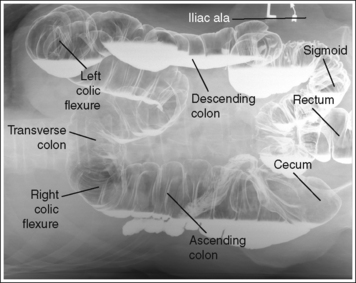
FIGURE 12-42 AP large intestine projection (right lateral decubitus position) with accurate positioning.
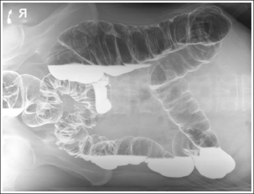
FIGURE 12-43 PA large intestine projection (left lateral decubitus position) with accurate positioning.
An arrow or word marker is present on the image, indicating the side of patient that was positioned up and away from the imaging table or cart.
• Place the marker superiorly, away from anatomic structures of interest, and within the collimated field.
Density is uniform across abdominal structures.
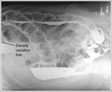
• Using a wedge-compensating filter. When an AP-PA (lateral decubitus) large intestine projection is obtained in a patient with excessive abdominal soft tissue, the soft tissue often drops toward the imaging table or cart. This movement results in a smaller AP measurement at the elevated side than at the side closer to the imaging table or cart. To compensate for this thickness difference, a wedge-compensating filter may be used. Attach the wedge-compensating filter to the x-ray collimator head with the thick end positioned toward the patient's “up” side (thinnest part of abdomen) and the thin end toward the patient's “down” side (thickest part of abdomen). Then set a technique that will accurately expose the middle section of the abdomen. When the filter has been accurately positioned, image density is uniform throughout the abdominal structures. Positioning the filter too close to or too far away from the thickest part of the abdomen results in an overexposed or underexposed area on the image, respectively, and a line of density difference. If the compensating filter is inaccurately positioned, a density variation line will appear, defining where the filter was and was not placed over the structures (see Image 16).
The abdomen demonstrates an AP or PA projection. The spinous processes are aligned with the midline of the vertebral bodies, the distances from the pedicles to the spinous processes are the same on both sides, and the iliac alae are symmetrical. The ascending and descending limbs of the colic flexures demonstrate some degree of superimposition.
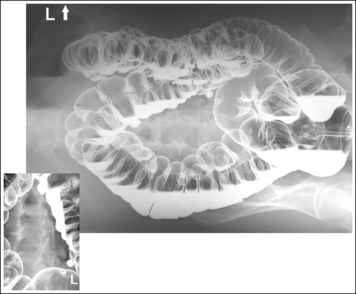
• AP or PA large intestine projections (lateral decubitus position) are obtained by placing the patient in left and right lateral recumbent positions on the imaging table or cart with the back or abdomen resting against a grid cassette or the upright IR holder. To avoid rotation, align the shoulders, the posterior ribs, and the posterior pelvis perpendicular to the imaging table or cart (Figure 12-44). Accomplish this alignment by resting an extended flat hand against each, respectively, and then adjusting the patient's rotation until the hand is positioned perpendicular to the imaging table or cart. Flex the patient's knees to support the patient's lateral position, although do not bring them to a 90-degree angle with the torso or they may be superimposed over the lateral aspect of the distal rectum (see Image 17). It is most common for a patient to rotate the elevated thorax and iliac ala anteriorly. A pillow or other support placed between the patient's flexed knees may help eliminate this forward rotation.
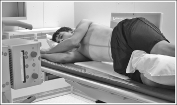
FIGURE 12-44 Proper patient positioning for AP large intestine projection (right lateral decubitus position).
• Detecting abdominal rotation. Rotation is effectively detected on a PA or AP lower intestine projection (lateral decubitus position) by comparing the distance from the pedicles to the spinous processes on each side, the symmetry of the iliac ala, and the superimposition of the colic flexures.
PA decubitus projection. The side demonstrating the greater distance from the pedicles to the spinous processes, wider iliac ala, and colic flexure with greater ascending and descending limb superimposition is the side positioned farther from the IR (see Image 18).
AP decubitus projection. The side demonstrating the greater distance from the pedicle to the spinous processes, wider iliac ala, and colic flexure with greater ascending and descending limb superimposition is the side positioned closer to the IR (see Image 19).
The abdominal field positioned against the imaging table or cart is demonstrated in its entirety and without artifact lines.
• Elevating the patient on a radiolucent sponge or hard surface such as a cardiac board positions the patient's abdomen above the IR's cassette border, preventing part of the abdomen from being clipped and preventing the abdomen from sinking into the table or cart pad. When the patient's body is allowed to sink into the cart pad, artifact lines are superimposed over the lateral abdominal field of the side that is down (see Image 17).
The fourth lumbar vertebra is centered within the exposure field. The entire large intestine, including the left colic (splenic) flexure and rectum, is included within the collimated field.
• To position the fourth lumbar vertebra in the center of the exposure field, center a perpendicular central ray with the patient's midsagittal plane at the level of the iliac crest. Center the IR to the central ray.
• The longitudinal collimated field should remain fully open. Transversely collimate to within 0.5 inch (1.25 cm) of the patient's lateral skin line.
• IR size and direction. A 14- × 17-inch (35- × 43-cm) lengthwise IR should be adequate to include all the required anatomic structures on sthenic and asthenic patients, as long as the transverse abdominal measurement is less than 14 inches (35 cm).
• Use two 14- × 17-inch (35- × 43-cm) crosswise IRs on hypersthenic patients and on other patients who have a transverse abdominal measurement of 14 inches (35 cm) or more to include all the necessary anatomic structures. Take the first projection with the central ray centered to the midsagittal plane at a level halfway between the symphysis pubis and ASIS. Position the bottom of the second IR so that it includes 2 to 3 inches (5 to 7.5 cm) of the same transverse section of the peritoneal cavity imaged on the first projection to ensure that no middle peritoneal information has been excluded. The top of the IR should extend to the patient's xiphoid (which is at the level of the tenth thoracic vertebra) to make sure that the left colic (splenic) flexure is included.
Anteroposterior or Posteroanterior Large Intestine Projection (Lateral Decubitus Position) Analysis
AP projection—the image density is not uniform across the abdomen. The right side of the abdomen is slightly underexposed, and the left side is slightly overexposed. Too much thickness of the compensating filter was positioned over the right side of the abdomen. A density difference line defines where the filter was and was not placed correctly over the abdomen.
Analysis
PA projection—artifact lines are superimposed over the left lateral abdominal region. The patient was not elevated on a radiolucent sponge. An underexposed area is present on the left side of the rectum. The patient's knee was bent to 90 degrees.
Correction
Elevate the patient on a radiolucent sponge or cardiac board to prevent the side of the abdomen from sinking into the table or cart pad. Decrease the amount of knee flexion.
Analysis
PA projection—the distance from the right pedicles to the spinous processes is less than the distance from the left pedicles to the spinous processes, the right iliac ala is narrower than the left, and the ascending and descending limbs of the left colic (splenic) flexure demonstrate increased superimposition. The right side of the patient was positioned closer to the IR than the left side.
Correction
Rotate the left side of the patient away from the IR until the shoulders and iliac ala are at equal distances to the IR.
Analysis
AP projection—the distance from the right pedicles to the spinous processes is less than the distance from the left pedicles to the spinous processes, the left iliac ala is wider than the right, and the left colic (splenic) flexure demonstrates increased superimposition. The left side of the patient was positioned closer to the IR than the right side.
LARGE INTESTINE: POSTEROANTERIOR OBLIQUE PROJECTION (RIGHT ANTERIOR OBLIQUE POSITION)
See Figure 12-45 and Box 12-14.
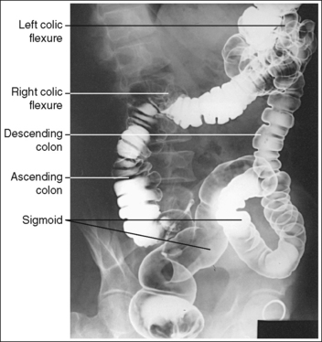
FIGURE 12-45 PA oblique large intestine projection (RAO position) with accurate positioning. (From Frank ED, Long BW, Smith BJ. Merrill's atlas of radiographic positions and radiologic procedures, vol 2, ed 10, St. Louis, 2007, Mosby, p. 179.)
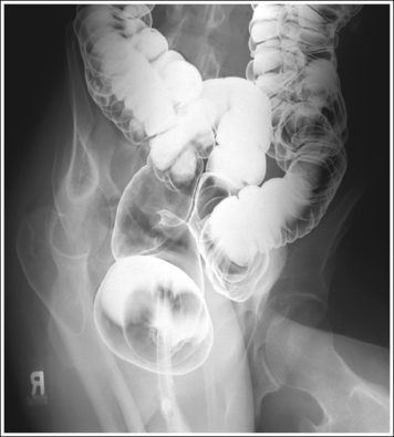
The ascending and descending limbs of the right colic (hepatic) flexure are demonstrated with decreased superimposition when compared with the PA projection, whereas the limbs of the left colic (splenic) flexure demonstrate increased superimposition and the rectosigmoid segments are demonstrated without transverse superimposition. The right iliac ala is narrow and the left is wide, and the distances from the right pedicles to the spinous processes are narrower than the distances from the left pedicles to the spinous processes.
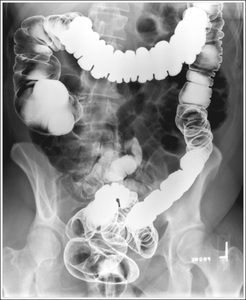
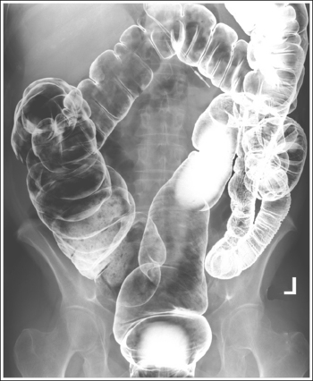
• A PA oblique large intestine projection (RAO position) is obtained by positioning the patient prone on the imaging table and then rotating the torso toward the right side until the midcoronal plane is at a 35- to 45-degree angle with the imaging table. In the PA projection, the descending limb of the right colic (hepatic) flexure is superimposed over the ascending limb and the rectum is superimposed over the distal sigmoid. Rotating the patient toward the right side moves the ascending right colic limb from beneath the descending limb and the distal sigmoid from beneath the rectum (transversely), allowing better visualization of these structures. The left elbow and knee are partially flexed and are used to support the patient and maintain accurate obliquity (Figure 12-46).
• Detecting inadequate rotation on a PA oblique projection. Insufficient rotation of the colon is demonstrated on the PA oblique projection when the ascending and descending limbs of the right colic flexure are superimposed and the rectum is superimposed over the distal sigmoid (see Image 20).
The midabdomen is at the center of the exposure field. The entire large intestine is included within the collimated field.
• To place the midabdomen in the center of the exposure field, center a perpendicular central ray approximately 1 to 2 inches (2.5 to 5 cm) to the left of the midsagittal plane at the level of the iliac crest. Center the IR to the central ray.
• The longitudinal collimated field should remain fully open. Transversely collimate to within 0.5 inch (1.25 cm) of the patient's lateral skin line.
• IR size and direction. A 14- × 17-inch (35- × 43-cm) IR placed lengthwise should be adequate to include all the required anatomic structures.
Posteroanterior Oblique Large Intestine Projection (Right Anterior Oblique Position) Analysis
LARGE INTESTINE: POSTEROANTERIOR OBLIQUE PROJECTION (LEFT ANTERIOR OBLIQUE POSITION)
See Figure 12-47 and Box 12-15.
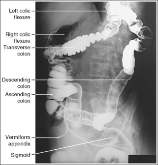
FIGURE 12-47 PA oblique large intestine projection (LAO position) with accurate positioning. (Frank ED, Long BW, Smith BJ. Merrill's atlas of radiographic positions and radiologic procedures, vol 2, ed 10, St. Louis, 2007, Mosby, p. 180.)
The ascending and descending limbs of the left colic (splenic) flexure are demonstrated with decreased superimposition when compared with the PA projection, whereas the limbs of the right colic (hepatic) flexure demonstrate increased superimposition. The left iliac ala is narrow and the right is wide, and the distances from the left pedicles to the spinous processes are narrower than the distances from the right pedicles to the spinous processes.
• A PA oblique large intestine projection (left anterior oblique [LAO]) is obtained by positioning the patient prone on the imaging table and then rotating the torso toward the left side until the midcoronal plane is at a 35- to 45-degree angle with the imaging table. In the PA projection, the descending limb of the left colic (splenic) flexure is superimposed over the ascending limb, and the rectum is superimposed over the distal sigmoid. Rotating the patient toward the left side moves the descending left colic limb from beneath the ascending limb, allowing better visualization of these structures. The right elbow and knee are partially flexed and are used to support the patient and maintain accurate obliquity (Figure 12-48).
• Detecting inadequate rotation on a PA oblique projection. Insufficient rotation of the colon is demonstrated on the PA oblique projection when the ascending and descending limbs of the left colic flexure are superimposed.
The midabdomen is at the center of the exposure field. The entire large intestine is included within the collimated field.
• To place the midabdomen in the center of the exposure field, center a perpendicular central ray approximately 1 to 2 inches (2.5 to 5 cm) to the right of the midsagittal plane at the level 1 to 2 inches (2.5 to 5 cm) superior to the iliac crest. Center the IR to the central ray.
• The longitudinal collimated field should remain fully open. Transversely collimate to within 0.5 inch (1.25 cm) of the patient's lateral skin line.
• IR size and direction. A 14- × 17-inch (35- × 43-cm) lengthwise IR placed lengthwise should be adequate to include all the required anatomic structures.
LARGE INTESTINE: POSTEROANTERIOR AXIAL PROJECTION OR POSTEROANTERIOR AXIAL OBLIQUE PROJECTION (RIGHT ANTERIOR OBLIQUE POSITION)
See Figure 12-49 and Box 12-16.
PA axial: The pelvis is demonstrated without rotation. The iliac alae and obturator foramen are symmetrical.
• A PA axial large intestine projection is obtained by positioning the patient prone on the imaging table with the legs extended. Position the shoulders and ASISs at equal distances from the imaging table to prevent rotation (Figure 12-50).
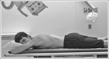
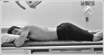
FIGURE 12-50 Proper patient positioning for PA axial oblique large intestine projection (RAO position).
• Detecting rotation on a PA axial projection. Rotation is effectively detected on a PA axial large intestine projection by evaluating the symmetry of the iliac alae and obturator foramen. If the patient was rotated away from the prone position, the iliac ala positioned farther from the IR will increase in width, the iliac ala positioned closer to the IR will narrow, the obturator foramina positioned farther from the IR will narrow, and the obturator foramina positioned closer to the IR will widen.
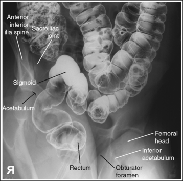
PA axial oblique projection (RAO position): The pelvis demonstrates adequate rotation when the rectosigmoid segments are demonstrated without transverse superimposition, the right sacroiliac (SI) joint is shown just medial to the ASIS, and the left obturator foramen is open.
• A PA axial oblique large intestine projection (RAO position) is obtained by positioning the patient prone on the imaging table and then rotating the torso toward the right side until the midcoronal plane is at a 35- to 45-degree angle with the imaging table. In the PA projection, the rectum is superimposed over the distal sigmoid, obscuring the rectosigmoid junction. Rotating the patient toward the right side moves the sigmoid from beneath the rectum (transversely), allowing better demonstration of this area. The left elbow and knee are partially flexed and are used to support the patient and maintain accurate obliquity (Figure 12-51).
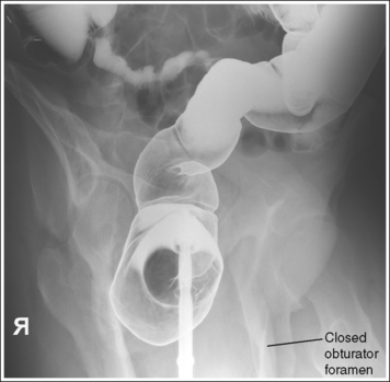
• Detecting inadequate rotation on a PA axial oblique projection. Insufficient pelvic rotation of the rectosigmoid and pelvic area is demonstrated on the PA axial oblique projection when the rectum is superimposed over the sigmoid colon, the right SI joint is too medial to the ASIS, and the left obturator foramen is narrowed. Too much pelvic rotation is demonstrated when the right SI joint is obscured and the left obturator foramen is closed (see Images 21 and 22).
The rectosigmoid segment is demonstrated without inferosuperior superimposition, the pelvis demonstrates elongation, and the left inferior acetabulum is at the level of the distal rectum.
• The PA axial oblique (RAO position) and PA axial projections of the large intestine are obtained to demonstrate the rectosigmoid area with less superimposition. To move the posteriorly situated rectum inferiorly and off the distal sigmoid, a 30- to 40-degree caudal angulation is used, decreasing rectosigmoid superimposition and better demonstrating the area. This angulation also elongates the pelvic structures.
• Inadequate angulation. When the rectosigmoid segment demonstrates inferosuperior overlap, the central ray angulation used was inadequate. If the inferior aspect of the left acetabulum is demonstrated superior to the distal rectum, the central ray was insufficient (see Image 21). If the inferior aspect of the left acetabulum is demonstrated inferior to the distal rectum, the central ray angulation was too great (see Image 22).
The rectosigmoid area is at the center of the exposure field. The rectum, sigmoid, and pelvic structures are included within the collimated field.
• PA axial projection. To place the rectosigmoid area at the center of the exposure field, center the central ray to exit at the level of the ASIS and to the midsagittal plane.
• PA axial oblique projection. To place the rectosigmoid area in the center of the field, center the central ray to the exit at the ASIS and 2 inches (5 cm) to the left of the lumbar spinous processes. Center the IR to the central ray.
• An 11- × 14-inch (28- × 35-cm) or 14- × 17-inch (35- × 43-cm) IR placed lengthwise should be adequate to include all the required anatomic structures.
Posteroanterior Axial Oblique Large Intestine Projection (Right Anterior Oblique Position) Analysis
The right SI joint is obscured. The pelvis was rotated more than 45 degrees. The inferior aspect of the left acetabulum is demonstrated superior to the distal rectum. The central ray was insufficient.
Correction
Decrease pelvic rotation until the midcoronal plane is at a 30- to 45-degree angle with the imaging table, and increase the degree of central ray angulation.