Cervical and Thoracic Vertebrae
Cervical Vertebrae: Anteroposterior Axial Projection
Cervical Atlas and Axis: Anteroposterior Projection (Open-Mouth Position)
Cervical Vertebrae: Lateral Projection
Cervical Vertebrae: Posteroanterior or Anteroposterior Axial Oblique Projection (Anterior and Posterior Oblique Positions)
Cervicothoracic Vertebrae: Lateral Projection (Twining Method; Swimmer's Technique)
After completion of this chapter, you should be able to do the following:
• Identify the required anatomy on cervical and thoracic vertebrae projections.
• Describe how to properly position the patient, image receptor (IR), and central ray for cervical and thoracic vertebrae projections.
• State how to properly mark and display each cervical and thoracic vertebrae projections.
• List the image analysis requirements for cervical and thoracic vertebrae projections with accurate positioning and state how to reposition the patient when less than optimal projections are produced.
• Explain how a patient with a suspected subluxation or fracture of the cervical vertebral column is positioned for cervical projections.
• Discuss the curvature of the cervical vertebrae and explain how the intervertebral disk spaces slant and how to obtain open disk spaces on AP projections.
• Describe why a 5-degree cephalic central ray angulation is often required for an AP open-mouth projection of the atlas and axis.
• State how the relationship between the dens and atlas's lateral masses changes when the patient's head is rotated.
• Describe how the prevertebral fat stripe is used as a diagnostic tool.
• Discuss when it is necessary to achieve a lateral cervicothoracic projection of the cervical vertebrae.
• List two methods used to obtain uniform image density on an AP thoracic vertebrae projection.
• Explain the breathing methods used to demonstrate the thoracic vertebrae on a lateral thoracic projection.
• Describe two methods that are used to offset the sagging of the lower thoracic column that results when the patient is in a lateral projection.
IMAGE ANALYSIS CRITERIA
The following image analysis criteria are used for all adult and pediatric cervical and thoracic projections and should be considered when completing the analysis for each projection presented in this chapter (Box 8-1).
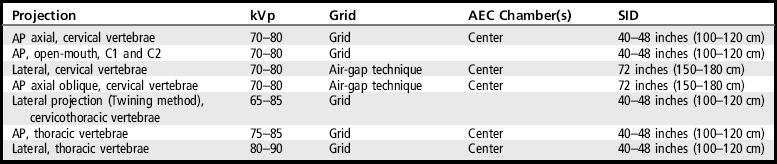
• Visibility of cervical and thoracic vertebral details. An optimal kilovoltage peak (kVp) technique, as shown in Table 8-1, sufficiently penetrates the cervical and thoracic vertebral structures and provides the contrast scale necessary to visualize the vertebral details. To obtain optimal density, set a manual milliampere-seconds (mAs) level based on the patient's thickness or choose the appropriate automatic exposure control (AEC) chamber. Table 8-1 lists the technical data for the most common projections.
CERVICAL VERTEBRAE: ANTEROPOSTERIOR AXIAL PROJECTION
See Figure 8-1 and Box 8-2.
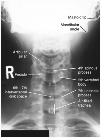
The cervical vertebrae demonstrate an AP axial projection. The spinous processes are aligned with the midline of the cervical bodies, the mandibular angles and mastoid tips are at equal distances from the cervical vertebrae, the articular pillars and pedicles are symmetrically demonstrated lateral to the cervical bodies, and the distances from the vertebral column to the medial (sternal) ends of the clavicles are equal.
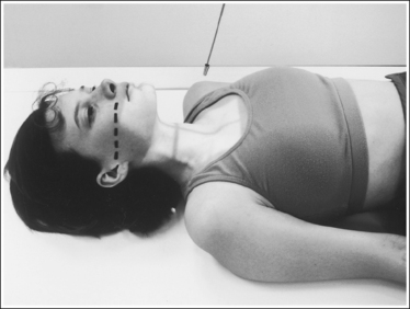
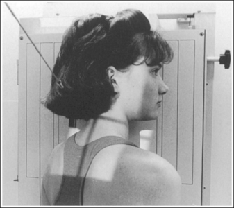
• An AP axial projection of the cervical vertebrae is obtained by placing the patient supine or upright, with the shoulders positioned at equal distances from the imaging table or upright image receptor (IR; Figure 8-2). The patient's face should be positioned so it is forward, placing the mandibular angles and mastoid tips at equal distances from the imaging table or upright grid holder.
• Effect of cervical rotation. When the patient and cervical vertebrae are rotated away from the AP axial projection, the vertebral bodies move toward the side positioned closer to the IR, and the spinous processes move toward the side positioned farther from the IR. The upper (C1 to C4) and lower (C5 to C7) cervical vertebrae can demonstrate rotation independently or simultaneously, depending on which part of the body is rotated. If the head is rotated but the thorax remains in an AP axial projection, the upper cervical vertebrae demonstrate rotation as C1 rotates on C2, and the lower cervical vertebrae remain in an AP axial projection. If the thorax is rotated but the head remains in a forward position to match, the lower cervical vertebrae demonstrate rotation and the upper cervical vertebrae remain in an AP axial projection. If the patient's head and thorax are rotated simultaneously, the entire cervical column demonstrates rotation (see Image 1).
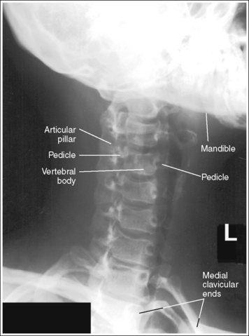
IMAGE 1
• Detecting rotation. Rotation is present on an AP axial projection in the following situations: (1) if the mandibular angles and mastoid tips are not demonstrated at equal distances from the cervical vertebrae; (2) if the spinous processes are not demonstrated in the midline of the cervical bodies; (3) if the pedicles and articular pillars are not symmetrically demonstrated lateral to the vertebral bodies; and (4) if the medial ends of the clavicles are not demonstrated at equal distances from the vertebral column (see Image 1). The side of the patient positioned closer to the imaging table or upright IR is the side toward which the mandible is rotated and also the side that demonstrates less of the articular pillars and less clavicular and vertebral column superimposition.
• Positioning for trauma. When cervical vertebral projections are exposed on a trauma patient with suspected subluxation or fracture, obtain the AP axial projection with the patient positioned as is. Do not attempt to remove the cervical collar or adjust the head or body rotation, mandible position, or cervical column tilting. This might result in greater injury to the vertebrae or spinal cord. Spinal cord injuries may occur from mishandling the patient after the initial injury has taken place.
The intervertebral disk spaces are open, the vertebral bodies are demonstrated without distortion, and each vertebra's spinous process is visualized at the level of its inferior intervertebral disk space.
• The cervical vertebral column demonstrates a lordotic curvature. This curvature and the shape of the vertebral bodies cause the disk-articulating surfaces of the vertebral bodies to slant upward anteriorly to posteriorly.
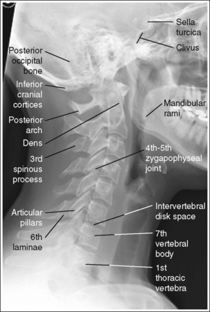
• Importance of central ray angulation. To obtain open intervertebral disk spaces and undistorted vertebral bodies, the central ray must be angled in the same direction as the slope of the vertebral bodies. This can be easily discerned by viewing the lateral cervical projection in Figure 8-3. Studying this lateral cervical projection, you can see that when the correct central ray angulation is used, each vertebra's spinous process is located within its inferior intervertebral disk space. The degree of central ray angulation needed to obtain open intervertebral disk spaces and to align the spinous processes within them accurately depends on the degree of cervical lordotic curvature.
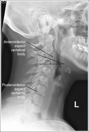
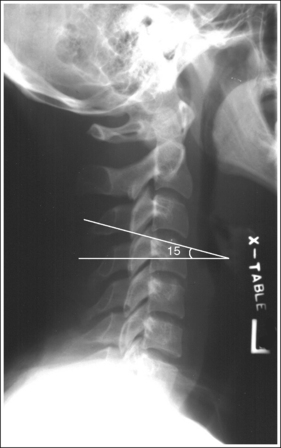
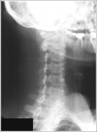
• Upright versus supine position. If the AP axial cervical vertebrae projection is performed with the patient in an upright position, the cervical vertebrae demonstrate more lordotic curvature than if the examination is performed with the patient supine. In a supine position, the gravitational pull placed on the middle cervical vertebrae results in straightening of the cervical curvature. Figure 8-3 demonstrates a lateral cervical projection taken with the patient in an upright position and Figure 8-4 demonstrates a lateral cervical projection taken with the patient supine. Note the difference in lordotic curvature between these two images. Because of this difference, the central ray angulation should be varied when an AP axial cervical vertebrae projection is taken with the patient erect rather than supine. In the erect position, a 20-degree cephalad central ray angulation is needed to align the central ray parallel with the intervertebral disk spaces. In the supine position, a 15-degree cephalad central ray angulation sufficiently aligns the central ray parallel with the intervertebral disk spaces.
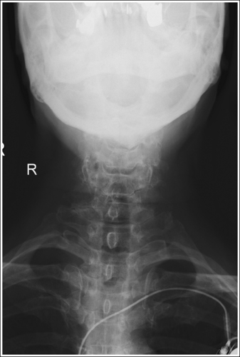
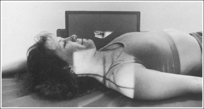
• Kyphotic patient. The kyphotic patient demonstrates an exaggerated kyphotic curvature of the thoracic vertebrae that will cause excessive lordotic curvature of the cervical vertebrae (Figure 8-5). To demonstrate the upper and lower cervical vertebrae with open intervertebral spaces for an upright AP axial cervical vertebrae projection, it will be necessary to increase the degree of central ray angulation above that routinely needed for a patient without kyphosis. If the AP axial projection is taken with the kyphotic patient in a supine position, a radiolucent sponge should be placed beneath the patient's head to prevent the upper cervical vertebrae from extending toward the imaging table and from superimposing the posterior occiput on the image (see Image 2).

• Effect of central ray misalignment. Misalignment of the central ray and intervertebral disk spaces results in closed disk spaces, distorted vertebral bodies, and projection of the spinous processes into the vertebral bodies. If the central ray angulation is not used or is insufficient, the resulting image demonstrates closed intervertebral disk spaces, and each vertebra's spinous process is demonstrated within its vertebral body (see Images 3 and 4). This anatomic relationship also results if the patient's head is tilted toward the x-ray tube for the examination, causing the cervical vertebrae to tilt anteriorly. If the central ray is angled more than needed to align the central ray parallel with the intervertebral disk spaces, or if the patient's cervical vertebral column was extended posteriorly for the examination, the resulting image demonstrates closed intervertebral disk spaces, each vertebra's spinous process is demonstrated within the inferior adjoining vertebral body, and the uncinate processes are elongated (see Image 5).
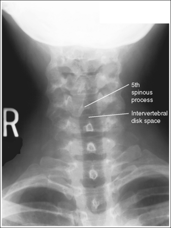
IMAGE 3
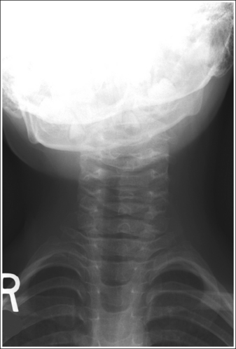
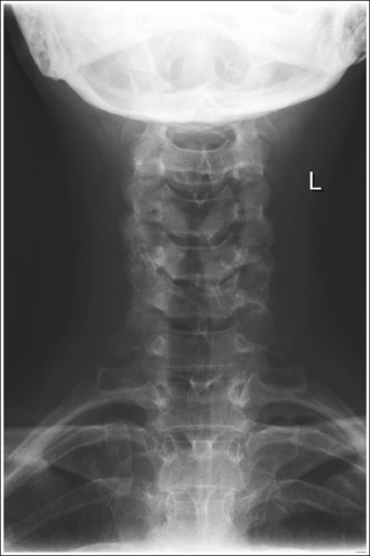
IMAGE 5
The third cervical vertebra is demonstrated in its entirety, and the posterior occiput and mandibular mentum are superimposed.
• Accurate positioning of the occiput and mandibular mentum is achieved when an imaginary line connecting the upper occlusal plane (chewing surface of maxillary teeth) and the base of the skull is aligned perpendicular to the imaging table or upright IR. This positioning also aligns the acanthiomeatal line (an imaginary line connecting the point at which the upper lip and nose meet with the external ear opening) perpendicular to the imaging table or upright IR (see Figure 8-2). With this position, you might expect the patient's mandible to be superimposed over the upper cervical vertebrae but this will not be the case because the cephalad central ray angulation used will project the mandible superiorly.
• Effect of occiput-mentum mispositioning. Mispositioning of the posterior occiput and the upper occlusal plane results in an obstructed image of the upper cervical vertebrae. If the occlusal plane is positioned superior to the base of the skull (head tilted too far backward), the upper cervical vertebrae are superimposed over the occiput (see Image 6). If the upper occlusal plane is positioned inferior to the base of the skull (chin tucked too far downward), the mandibular mentum is superimposed over the superior cervical vertebrae (see Image 7).
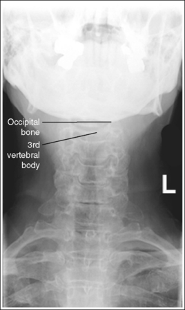
IMAGE 6
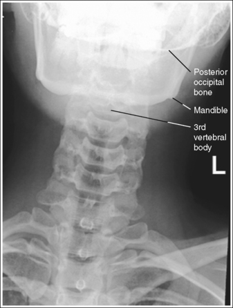
IMAGE 7
The long axis of the cervical column is aligned with the long axis of the exposure field.
• Aligning the long axis of the cervical column with the long axis of the collimated field ensures that no lateral flexion of the cervical column is present (see Image 8) and allows for tight collimation (see Image 7). This alignment is obtained by aligning the midline of the patient's neck with the collimator's longitudinal light line.
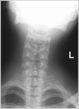
IMAGE 8
The fourth cervical vertebra is centered within the exposure field. The second through seventh cervical vertebrae and the surrounding soft tissue are included within the collimated field.
• Center the central ray to the patient's midsagittal plane at a level halfway between the external auditory meatus (EAM) and the jugular notch to center C4 to the collimated field.
• Open the longitudinal collimation to the EAM and the jugular notch. Transverse collimation should be to within 0.5 inch (1.25 cm) of the lateral neck skin line.
• An 8- × 10-inch (18- × 24-cm) IR placed lengthwise should be adequate to include all the required anatomic structures.
Anteroposterior Axial Cervical Vertebrae Projection Analysis
The spinous processes are not aligned with the midline of the cervical bodies, and the pedicles and articular pillars are not symmetrically demonstrated lateral to the vertebral bodies. The mandible is rotated toward the patient's left side, and the medial end of the left clavicle demonstrates no vertebral column superimposition. The patient was rotated toward the left side (left posterior oblique [LPO] position).
Correction
Rotate the patient toward the right side until the shoulders are at equal distances from the imaging table or upright grid holder, and turn the patient's head toward the right side until the mandibular angles and mastoid tips are at equal distances from the imaging table or upright grid holder.
Analysis
The intervertebral disk spaces are closed, with the spinous processes of C6 and C7 within their vertebral bodies and the spinous processes of C4 and C5 within the inferior adjoining vertebral bodies. The uncinate processes of C5 and C6 are elongated and C1 through C3 are superimposing the posterior occiput. The central ray angulation was not used or was insufficient to align the central ray parallel with the intervertebral disk spaces of C6 and C7 and too cephalic to align the central ray parallel with the intervertebral disk spaces of C4 and C5, and the upper cervical vertebrae was extended posteriorly to rest the patient's head on the imaging table.
Correction
Increase the degree of cephalic central ray angulation to align it with the C6-C7 intervertebral disk space, tuck the patient's chin toward the chest, and elevate the head on a radiolucent sponge until an imaginary line connecting the upper occlusal plane and base of the skull is aligned perpendicular to the imaging table.
Analysis
The anteroinferior aspects of the cervical bodies (see Figure 8-3 for identification) are obscuring the intervertebral disk spaces, and each vertebra's spinous process is demonstrated within its vertebral body. The central ray angulation was not used or was insufficient to align the central ray parallel with the intervertebral disk spaces.
Analysis
The anteroinferior aspects of the cervical bodies are obscuring the intervertebral disk spaces, and each vertebra's spinous process is demonstrated within its vertebral body. The central ray angulation was not used or was insufficient to align the central ray parallel with the intervertebral disk spaces.
Analysis
The posteroinferior aspects of the cervical bodies (see Figure 8-3 for identification) are obscuring the intervertebral disk spaces, the uncinate processes are elongated, and each vertebra's spinous process is demonstrated within the inferior adjoining vertebral body. The central ray was angled too cephalically to align the central ray parallel with the intervertebral disk spaces.
Analysis
A portion of the third cervical vertebra is superimposed over the posterior occipital bone, preventing a clear visualization of the third cervical vertebra. The upper occlusal plane was positioned superior to the base of the skull.
Correction
Tuck the chin half the distance demonstrated between the base of the skull and mandibular mentum, or until an imaginary line connecting the upper occlusal plane and the base of the skull is aligned perpendicular to the imaging table or upright grid holder. For this patient, the movement should be approximately 1 inch (2.5 cm).
Analysis
The mandible is superimposed over a portion of the third cervical vertebra. The upper occlusal plane was positioned inferior to the base of the occiput. The long axis of the cervical column is not aligned with the long axis of the collimated field, preventing tight collimation.
Correction
Raise the chin half the distance shown between the base of the skull and mandibular mentum, or until an imaginary line connecting the upper occlusal plane and the inferior base of the posterior occiput is aligned perpendicular to the imaging table or upright grid holder. Align the long axis of the cervical column with the long axis of the collimated field, and increase transverse collimation.
CERVICAL ATLAS AND AXIS: ANTEROPOSTERIOR PROJECTION (OPEN-MOUTH POSITION)
See Figure 8-6 and Box 8-3.
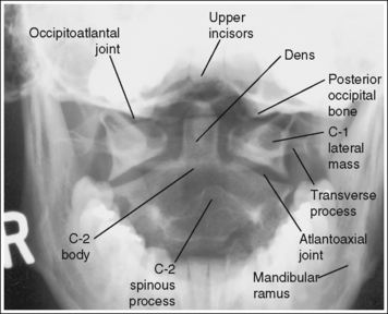
The atlas and axis demonstrate an AP projection. The atlas is symmetrically seated on the axis, with the atlas's lateral masses at equal distances from the dens. The spinous process of the axis is aligned with the midline of the axis's body, and the mandibular rami are demonstrated at equal distances from the lateral masses.
• An AP projection of the atlas and axis is obtained by placing the patient in a supine or upright position, with the shoulders, mandibular angles, and mastoid tips positioned at equal distances from the imaging table or upright IR (Figure 8-7).
• Effect of rotation. Rotation of the atlas and axis occurs when the head is turned away from an AP projection. On head rotation, the atlas pivots around the dens so that the lateral mass located on the side the face is rotated toward is displaced posteriorly and the mass toe side the face is rotated away from is displaced anteriorly. This displacement causes the space between the lateral mass and dens to narrow on the side the face is rotated away from and to enlarge on the side the face is rotated toward (see Image 9). As the amount of head rotation increases, the axis rotates in the same direction as the atlas, resulting in a shift in the position of its spinous process in the direction opposite that in which the patient's face is turned.
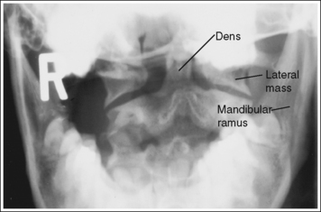
IMAGE 9
• Detecting direction of rotation. To determine how the patient's face was turned, judge the distance between the mandibular rami and lateral masses. The side that demonstrates the greater distance is the side toward which the face was rotated.
• Positioning for trauma. When cervical vertebrae projections are taken on a trauma patient with suspected subluxation or fractures, obtain the AP cervical atlas and axis projection with the patient's position left as is. Do not attempt to remove the cervical collar or adjust head or body rotation, mandible position, or cervical vertebral column tilting. To do so might result in increased injury to the vertebrae or spinal cord.
The upper incisors and the base of the skull are demonstrated superior to the dens and the atlantoaxial joint.
• The dens and the atlantoaxial joint are located at the midsagittal plane, at a level 0.5 inch (1.25 cm) inferior to an imaginary line connecting the mastoid tips. To demonstrate them without upper incisor (front teeth) or posterior occiput superimposition, instruct the patient to open the mouth as widely as possible. Then have the patient tuck the chin until an imaginary line connecting the upper occlusal plane (chewing surface of maxillary teeth) and the base of the skull is aligned perpendicular to the imaging table or upright grid holder. If the patient does not have upper teeth, one should imagine where the occlusal plane would be if the patient had teeth. This positioning also aligns the acanthiomeatal line (an imaginary line drawn between the point where the upper lip and nose meet the external ear opening) perpendicular with the imaging table or upright grid holder. It may be necessary to position a small angled sponge beneath the patient's head to maintain accurate head positioning, especially if the patient's chin has to be tucked so much that it is difficult to open the mouth adequately. The sponge causes the upper occlusal plane and base of the skull to align perpendicularly without requiring as much chin tucking.
• Relationship of central ray angulation and patient position. The lateral cervical projection in Figure 8-8 demonstrates how the occlusal plane and the base of the skull should be aligned for an accurate open-mouth AP projection. After studying this image, you might conclude that the atlantoaxial joint will be free of upper incisor or occiput superimposition if the patient maintains this head position and simply drops the jaw. Because the upper incisors are positioned at a long object–image receptor distance (OID), however, they are greatly magnified, causing them to be projected onto the dens and atlantoaxial joint. In most patients, when the upper occlusal plane and base of the skull are superimposed, magnification causes the upper incisors to be projected approximately 1 inch (2.5 cm) inferior to the base of the skull (see Image 10). For these incisors to be projected superiorly, a 5-degree cephalic angle should be placed on the central ray. The upper incisors will be projected approximately 1 inch (2.5 cm) for every 5 degrees of angulation. This angle adjustment is based on a 40-inch (102-cm) SID; if a longer SID is used, the required angle adjustment would be less, whereas if a shorter SID is used, the angulation adjustment would be greater. If, instead of an angle adjustment, the patient's chin were tilted upward in an attempt to shift the upper incisors superiorly, the posterior occiput would simultaneously be shifted inferiorly.
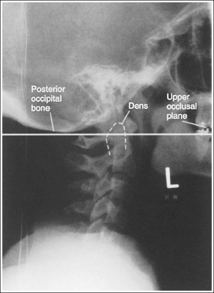
FIGURE 8-8 Lateral cervical vertebral projection demonstrating upper incisor, dens, and posterior occiput relationship.
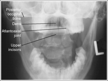
IMAGE 10
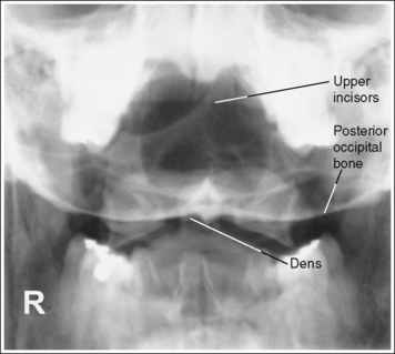
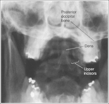
• This inferior shift of the occiput would obscure the dens and possibly the atlantoaxial joint. The dens and atlantoaxial joint space may also be obscured if a 5-degree cephalad central ray angle was used but the occlusal plane and base of the skull were not superimposed. When the base of the skull is positioned inferior to the upper occlusal plane, the image demonstrates the dens and, depending on the degree of mispositioning, the atlantoaxial joint space superimposed onto the posterior occiput (see Image 11). When the occlusal plane is positioned inferior to the base of the skull, the posterior occiput is demonstrated superior to the dens, and the upper incisors are superimposed over a portion of the superior dens (see Image 12).
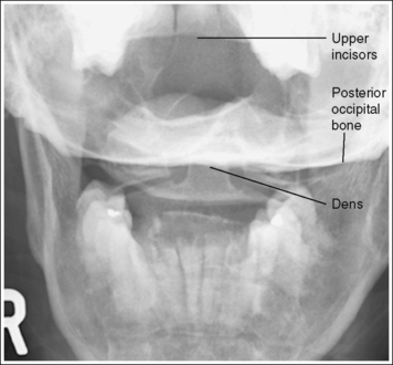
IMAGE 11
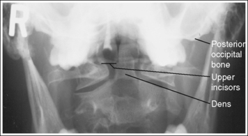
IMAGE 12
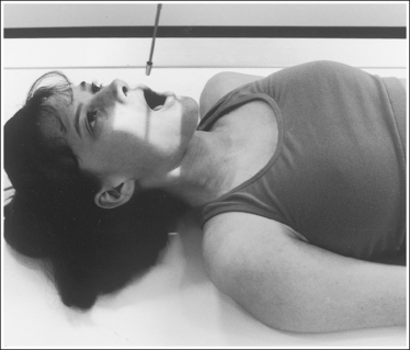
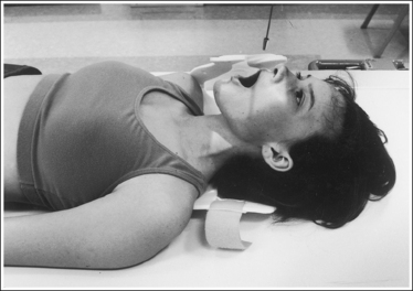
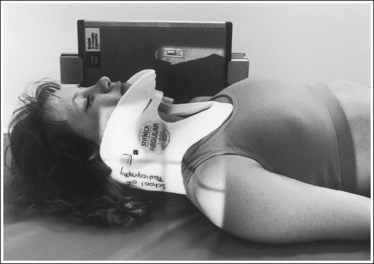
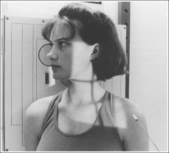
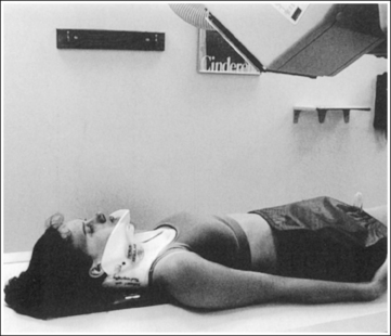
• Positioning for trauma. For the dens and atlantoaxial joint to be demonstrated without incisor or occiput superimposition in a trauma patient, the direction of the central ray must be changed from the standard position. A trauma patient's head and neck cannot be adjusted, so you must angle the central ray until it is aligned parallel with the infraorbitomeatal line (IOML) (imaginary line connecting the inferior orbital rim and the external ear opening). This line is easily accessible in a patient wearing a cervical collar. The exact degree of angulation needed depends on the amount of chin elevation. Most patients in a cervical collar require approximately a 10-degree caudal angle. Once the angle is set, attempt to get the patient to drop the lower jaw. Do not adjust head rotation or tilting. If the cervical collar allows the lower jaw to move without elevating the upper jaw, instruct the patient to drop the lower jaw. If the cervical collar prevents lower jaw movement without elevating the upper jaw, instruct the patient about the importance of holding the head and neck perfectly still; then have the ordering physician remove the front of the cervical collar so that the patient can drop the jaw without adjusting the head or neck position (Figure 8-9). After the patient's jaw is dropped, align the central ray to the midsagittal plane at a level 0.5 inch (1.25 cm) inferior to the occlusal plane. Immediately after the image is taken, the physician should return the front of the cervical collar to its proper position. For trauma positioning, insufficient caudal angulation causes the upper incisors to be demonstrated superior to the dens and the dens to be superimposed over the posterior occiput (see Image 13). If the central ray was angled too caudally, the posterior occiput is demonstrated superior to the dens and the upper incisors are superimposed over the dens (see Image 14).
The atlantoaxial joint is open, and the axis's spinous process is demonstrated in the midline and slightly inferior to the dens.
• AP neck extension and flexion determine the alignment of the atlantoaxial joint with the imaging table and the position of the axis's spinous process to the dens. When the occlusal plane and base of the skull are aligned perpendicular to the imaging table, the atlantoaxial joint should be open.
• Effect of cervical column flexion and extension. If the cervical column is flexed, the atlantoaxial joint is closed and the spinous process of the axis is demonstrated closer to the dens (see Image 15). If the cervical column is extended, the atlantoaxial joint is closed and the spinous process of the axis is demonstrated more inferiorly to the dens.
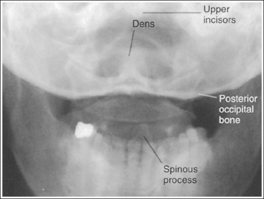
IMAGE 15
The dens is centered within the exposure field. The atlantoaxial and occipitoatlantal joints, the atlas's lateral masses and transverse processes, and the axis's dens and body are included within the collimated field.
• Center the central ray through the open mouth to the midsagittal plane to center the dens to the center of the exposure field.
• Open the longitudinally collimated field to the patient's external ear opening. Transverse collimation should be to a 5-inch (12.5-cm) field size.
• An 8- × 10-inch (18- × 24-cm) IR placed lengthwise should be adequate to include all the required anatomic structures.
Anteroposterior Cervical Atlas and Axis Projection Analysis
The distances from the atlas's lateral masses to the dens and from the mandibular rami to the dens are narrower on the left side than on the right side, and the axis's spinous process is shifted from the midline toward the left. The face was rotated toward the right side.
Correction
Rotate the face toward the left side until the mandibular angles and mastoid tips are positioned at equal distances from the imaging table or upright grid holder.
Analysis
The upper incisors are demonstrated approximately 1 inch (2.5 cm) inferior to the base of the skull, obscuring the dens and atlantoaxial articulation. The base of the skull is demonstrated directly superior to the dens.
Correction
If the upper occlusal plane and the base of the skull were aligned perpendicular to the imaging table and a perpendicular central ray was used for this image, do not adjust patient positioning; simply direct the central ray 5 degrees cephalad. If a 5-degree cephalad angulation was used for this image, do not adjust patient positioning; simply increase the cephalad angulation by 5 degrees. The incisors will shift approximately 1 inch (2.5 cm) for every 5 degrees of central ray angulation. (This angle adjustment is based on a 40-inch [102-cm] SID; if a longer SID is used, less angle adjustment is required; if a shorter SID is used, more angle adjustment is required.)
Analysis
The dens is superimposed over the posterior occiput. The upper incisors are demonstrated approximately 1.5 inches (3.75 cm) superior to the base of the skull. The patient's head was not accurately positioned.
Correction
Tuck the chin toward the chest until an imaginary line connecting the upper occlusal plane with the base of the skull is aligned perpendicular to the IR. The needed movement is equal to half the distance demonstrated between the upper incisors and base of the skull. For this patient, the chin should be tucked approximately 0.75 inch (2 cm).
Analysis
The upper incisors are superimposed over the dens. The base of the skull is demonstrated approximately 0.5 inch (1.25 cm) superior to the upper incisors and 0.25 inch (0.6 cm) superior to the dens. The upper occlusal plane was positioned inferior to the base of the skull.
Correction
Elevate the upper jaw until an imaginary line connecting the upper occlusal plane with the base of the skull is aligned perpendicular to the IR. The needed movement is equal to half the distance demonstrated between the upper incisors and the base of the skull. For this patient, the upper occlusal plane should be elevated approximately 0.25 inch (0.6 cm).
Analysis
The upper incisors are demonstrated superior to the dens and the base of the skull, and the dens is superimposed over the posterior occiput. The central ray angulation was not directed enough caudally.
Correction
Angle the central ray approximately 5 degrees caudad for every 1 inch (2.5 cm) demonstrated between the upper incisors and the base of the skull. (This angle adjustment is based on a 40-inch [102-cm] SID.) Because approximately 1 inch (2.5 cm) is demonstrated between the upper incisors and base of the skull on this image, the central ray angulation should be adjusted approximately 5 degrees caudally.
Analysis
The upper incisors are superimposed over the dens, and the base of the skull is situated superior to the dens and upper incisors. The central ray was angled too caudally.
Correction
Angle the central ray approximately 5 degrees cephalically for every 1 inch (2.5 cm) demonstrated between the upper incisors and base of the skull.
Analysis
The atlantoaxial joint is closed, the posterior occipital bone is superimposed over the dens, the upper incisors appear superior to the posterior occipital bone, and the axis's spinous process is demonstrated too inferior to the dens. The patient's head was not accurately positioned, and the cervical column was extended.
CERVICAL VERTEBRAE: LATERAL PROJECTION
See Figure 8-10 and Box 8-4.
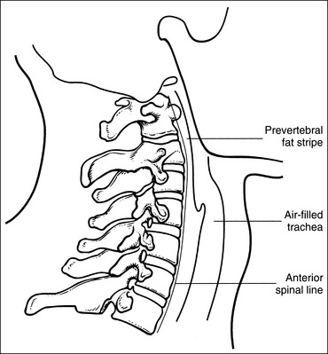
Contrast and density are adequate to demonstrate the prevertebral fat stripe.
• Prevertebral fat stripe. The soft tissue structure of interest on a lateral cervical projection is the prevertebral fat stripe. It is located anterior to the cervical vertebrae and is visible on correctly exposed lateral cervical projections with accurate positioning (Figure 8-11). The reviewer evaluates the distance between the anterior surface of the cervical vertebrae and the prevertebral fat stripe. Abnormal widening of this space is used for the detection and localization of fractures, masses, and inflammation.
The cervical vertebrae demonstrate a lateral projection. The anterior and posterior aspects of the right and left articular pillars and the right and left zygapophyseal joints of each cervical vertebra are superimposed, and the spinous processes are in profile.
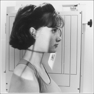
• A lateral cervical vertebral projection is obtained by placing the patient in an upright position with the midcoronal plane positioned perpendicular to the IR (Figure 8-12). In this position the right and left sides of each cervical vertebra are superimposed, demonstrating the spinous processes and vertebral bodies in profile. To prevent rotation, superimpose the patient's shoulders, mastoid tips, and mandibular rami.
• Effect of rotation. The upper and lower cervical vertebrae can demonstrate rotation simultaneously or separately, depending on which part of the body is rotated. If the head was rotated and the thorax remained in a lateral projection, the upper cervical vertebrae demonstrate rotation. If the thorax was rotated and the head remained in a lateral projection, the lower cervical vertebrae demonstrate rotation. If the patient's head and thorax were rotated simultaneously, the entire cervical column demonstrates rotation.
• Detecting rotation. Rotation can be detected on a lateral cervical projection by evaluating each vertebra for anterior and posterior pillar superimposition and for zygapophyseal joint superimposition. When the patient is rotated, the pillars and zygapophyseal joints on one side of the vertebra move anterior to those on the other side (see Images 16 and 17). Because the two sides of the vertebrae are mirror images, it is very difficult to determine from a rotated lateral cervical projection which side of the patient is rotated anteriorly and which is rotated posteriorly. The magnification of the side situated farther from the IR may provide a moderately reliable clue at the articular pillar regions.
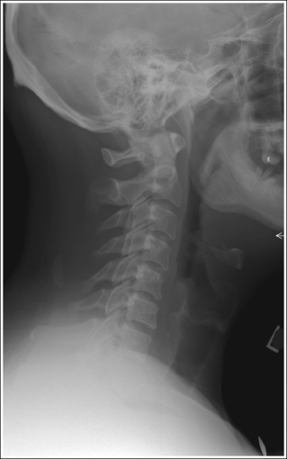
IMAGE 16
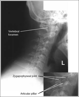
IMAGE 17
• Positioning for trauma. When cervical vertebral projections are taken of a trauma patient with suspected subluxation or fracture, take the lateral projection with the patient's position left as is. Do not attempt to remove the cervical collar or adjust head or body rotation, mandible position, or vertebral tilting. This might result in increased injury to the vertebrae or spinal cord. A trauma lateral cervical vertebral projection is obtained by placing a lengthwise IR against the patient's shoulder and directing a horizontal beam to the cervical vertebrae (Figure 8-13). Such an image should meet as many of the analysis requirements listed for a nontrauma lateral projection as possible without moving the patient. A 10- × 12-inch (24- × 30-cm) IR may be needed to include all the required structures.
The posterior arch of C1 and the spinous process of C2 are in profile without posterior occiput superimposition, and their bodies are demonstrated without mandibular superimposition. The cranial cortices and the mandibular rami are superimposed, the superior and inferior aspects of the right and left articular pillars and the zygapophyseal joints of each cervical vertebra are superimposed, and the intervertebral disk spaces are open.
• When the patient is positioned for a lateral cervical projection, place the head in a lateral projection with the midsagittal plane aligned parallel with the IR and the chin is elevated until the acanthiomeatal line is aligned parallel with the floor and the interpupillary line is aligned perpendicular to the IR. This positioning accomplishes five goals: alignment of the cervical vertebral column parallel with the IR; demonstration of C1 and C2 without occiput or mandibular superimposition; superimposition of the anterior and posterior and superior and inferior aspects of the cranial and mandibular cortices, and of the superior and inferior aspects of the right and left articular pillars and zygapophyseal joints.
• Effect of mandibular rotation and elevation on C1 and C2 visualization. The position of the mandible and demonstration of C1 and C2 on a lateral cervical vertebrae projection are affected by head positioning. The posterior cortices of the mandibular rami are superimposed when the head's midsagittal plane was aligned parallel with the IR. If the posterior cortices of the mandibular rami are not superimposed on a lateral cervical vertebrae projection, one mandibular ramus is superimposed over the bodies of C1 and/or C2 and the other is situated anteriorly (see Image 18).
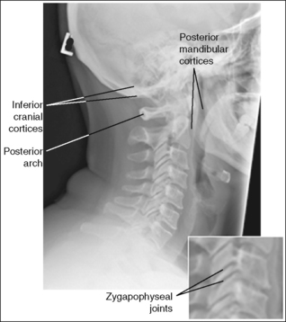
IMAGE 18
If the chin was elevated adequately to place the acanthiomeatal line parallel with the floor, the mandibular rami are demonstrated anterior to the vertebral column. If the patient's chin was not adequately elevated, the mandibular rami are superimposed over the bodies of C1 and/or C2 (see Image 19).
IMAGE 19
• Detecting head and shoulder tilting that causes lateral cervical flexion. If the patient's head is tilted toward or away from the IR enough to flex the upper cervical column laterally, or if the shoulders are not placed on the same plane but are tilted enough to flex the lower cervical column laterally, the lateral cervical projection will demonstrate a superoinferior separation between the right and left articular pillars and zygapophyseal joints of the flexed vertebrae (see Images 18 and 20). Head tilting will also result in a superoinferior separation between the cranial cortices and between the mandibular rami; this can be avoided by positioning the interpupillary line (imaginary line connecting the outer corners of the eyelids) parallel with the floor. If the head was tilted toward the IR, neither the superior or the inferior cortices of the cranium nor the mandibular rami are superimposed, and the vertebral foramen of C1 is demonstrated (see Image 20). If the head and upper cervical vertebral column were tilted away from the IR, neither the inferior cortices of the cranium nor the mandibular rami are superimposed, and the posterior arch of C1 remains in profile (see Image 18).
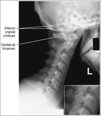
IMAGE 20
The long axis of the cervical vertebral column is aligned with the long axis of the exposure field.
• Aligning the long axis of the cervical vertebral column with the long axis of the exposure field ensures against flexion or extension of the cervical column and allows for tight collimation. This alignment is obtained by positioning the patient's neck vertically and aligning the midline of the patient's neck with the collimator's longitudinal light line; it places the cervical column in a neutral position.
• Hyperflexion and hyperextension positioning to evaluate AP mobility of cervical vertebrae. Hyperflexion and hyperextension lateral cervical vertebrae projections are obtained to evaluate AP vertebral mobility. For hyperflexion, instruct the patient to tuck the chin into the chest as far as possible (Figure 8-14). For patients who demonstrate extreme degrees of flexion, it may be necessary to place the IR crosswise to include the entire cervical column on the same image. Such an image should meet all the analysis requirements listed for a neutral lateral projection, except that the long axis demonstrates forward bending (see Image 21). For hyperextension, instruct the patient to extend the chin up and backward as far as possible (Figure 8-15). Such an image should meet all the analysis requirements listed for a neutral lateral projection, except that the long axis demonstrates backward bending (see Image 22). If the lateral projection is used with the patient in hyperflexion or hyperextension, an arrow pointing in the direction the neck is moving or a flexion or extension marker should be included to indicate the direction of neck movement.
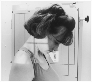
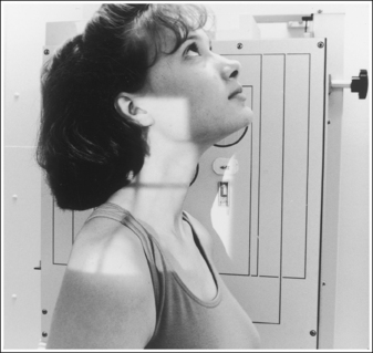
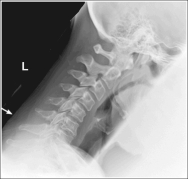
IMAGE 21
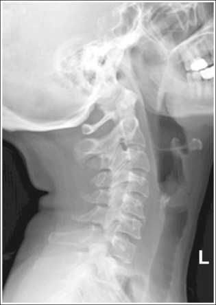
IMAGE 22
The fourth cervical vertebra is centered within the exposure field. The sella turcica, clivus, first through seventh cervical vertebrae, and superior half of the first thoracic vertebra and the surrounding soft tissue are included within the collimated field.
• Center a perpendicular central ray to the midcoronal plane at a level halfway between the EAM and the jugular notch to center C4 to the exposure field.
• Open the longitudinally and transversely collimated field enough to include the clivus and sella turcica, which is at a level 0.75 inch (2 cm) anterosuperior to the EAM. (The clivus, a slanted structure that extends posteriorly off the sella turcica, and the dens are used to determine cervical injury. A line drawn along the clivus should point to the tip of the dens on the normal upper lateral cervical vertebrae projection.)
• An 8- × 10-inch (18- × 24-cm) IR placed lengthwise should be adequate to include all the required anatomic structures.
• Demonstration of C7 and T1 vertebrae. The seventh cervical vertebra and first thoracic vertebra are located between the patient's shoulders. This location makes it difficult to demonstrate them because of the great difference in lateral thickness between the neck and the shoulders. The best method to demonstrate C7 is to have the patient hold 5- or 10-lb weights on each arm to depress the shoulders and attempt to move them inferior to C7. Weights are best placed on each arm rather than in each hand, because sometimes the patient's shoulders will elevate when weights are placed in the hands. Without weights, it is often difficult to demonstrate more than six cervical vertebrae (see Image 23). Taking the image on expiration also aids in lowering the shoulders.
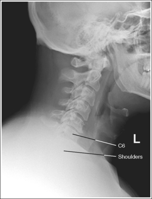
IMAGE 23
• Visualization of C7 and T1 in trauma or recumbency. For trauma or recumbent patients who do not have upper extremity or shoulder injuries, depress the shoulders by having a qualified assistant, with the consent of a physician, pull down on the patient's arms while the image is taken. To accomplish this, instruct an assistant to wear a protection apron and stand at the end of the imaging table or stretcher, with the patient's feet resting against the assistant's abdomen and the assistant's hands wrapped around the patient's wrists. The assistant should slowly pull on the patient's arms until the shoulders are moved inferiorly as much as possible.
• Demonstration C7. If even after using weights to depress the patient's shoulders C7 cannot be demonstrated in its entirety, a special image known as the lateral cervicothoracic projection (Twining method, Swimmer's technique) should be taken. Refer to page 449 for specifics.
Lateral Cervical Vertebrae Projection Analysis
The articular pillars and zygapophyseal joints on one side of the patient are situated anterior to those on the other side. The patient was rotated.
Analysis
The articular pillars and zygapophyseal joints on one side of the patient are situated anterior to those on the other side. The patient was rotated. The inferior cortices of the cranium and mandible are demonstrated without superimposition, and the vertebral foramen of C1 is visualized. The patient's head and upper cervical vertebral column were tilted toward the IR.
Correction
Rotate the patient until the midcoronal plane is aligned perpendicular to the IR, and tilt the head away from the IR until the interpupillary line is perpendicular to the IR.
Analysis
The inferior and posterior cortices of the cranium and the mandible are not superimposed; the posterior arch of C1 is in profile, and the right and left articular pillars and zygapophyseal joints demonstrate a superoinferior separation. The patient's head was rotated and the patient's head and upper cervical vertebrae were tilted away from the IR.
Correction
Rotate the patient until the midsagittal plane is aligned parallel with the IR, and then tilt the head toward the IR until the interpupillary line is perpendicular to the IR.
Analysis
The articular pillars and zygapophyseal joints on one side of the patient are situated anterior to those on the other side. The patient was rotated. The cranial and mandibular cortices are accurately aligned, and the mandibular rami are superimposed over the body of C2. The patient's chin was not adequately elevated.
Correction
Rotate the patient until the midcoronal plane is aligned perpendicular to the IR. Elevate the chin until the acanthiomeatal line is aligned parallel with the floor.
Analysis
The inferior cortices of the cranium and mandible are demonstrated without superimposition, the vertebral foramen of C1 is visualized, and the right and left articular pillars and zygapophyseal joints demonstrate a superoinferior separation. The patient's head and upper cervical vertebrae were tilted toward the IR.
Correction
Tilt the head away from the IR until the interpupillary line is aligned perpendicular to the IR.
Analysis
The long axis of the cervical vertebral column is not aligned with the long axis of the collimated field. The cervical vertebral column is tilted forward. The patient was in hyperflexion.
Correction
Extend the patient's chin until the eyes are facing forward and the long axis of the neck is aligned with the long axis of the collimated field. If this examination is being performed to evaluate AP mobility, no corrective movement is required.
Analysis
The long axis of the cervical vertebral column is not aligned with the long axis of the collimated field. The cervical vertebral column is tilted backward. The patient was in hyperextension.
Correction
Tuck the patient's chin until the eyes are facing forward and the long axis of the neck is aligned with the long axis of the collimated field. If this examination is being performed to evaluate AP mobility, no corrective movement is required.
Analysis
The vertebral body of C7 is not demonstrated in its entirety and the superior body of T1 is not demonstrated. The shoulders were not adequately depressed.
Correction
If possible, have the patient hold 5- to 10-lb weights on each arm to depress the shoulders. If the patient cannot hold weights or if the weights do not sufficiently drop the shoulders, a special image known as the cervicothoracic lateral projection (Twining method) should be taken to demonstrate this area (refer to page 449 for details).
CERVICAL VERTEBRAE: POSTEROANTERIOR OR ANTEROPOSTERIOR AXIAL OBLIQUE PROJECTION (ANTERIOR AND POSTERIOR OBLIQUE POSITIONS)
See Figures 8-16 and 8-17 and Box 8-5.
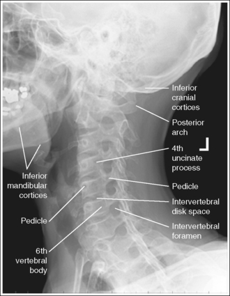
FIGURE 8-16 PA axial oblique cervical vertebrae projection with cranium in lateral projection and accurate positioning.
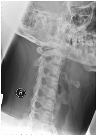
FIGURE 8-17 PA axial oblique cervical vertebrae projection with cranium in PA oblique projection and accurate positioning.
The cervical vertebrae have been rotated 45 degrees. The second through seventh intervertebral foramina are open, demonstrating uniformity in size and shape, the pedicles of interest are in profile, and the opposite pedicles are aligned with the anterior vertebral bodies. The sternum and sternoclavicular joints, when visible, are demonstrated without vertebral column superimposition.
• To position the intervertebral foramina and pedicles of interest in profile, begin by placing the patient in a recumbent or upright PA-AP axial oblique projection. Rotate the patient from this position until the midcoronal plane is at a 45-degree angle to the imaging table or upright IR. To demonstrate the foramina and pedicles on both sides of the cervical vertebrae, right and left oblique projections must be taken. When PA axial oblique projections (Figure 8-18) are obtained, the foramina and pedicles situated closer to the IR are demonstrated, whereas AP axial oblique projections (Figure 8-19) demonstrate the foramina and pedicles situated farther from the IR.
• Effect of incorrect rotation. If the cervical vertebral rotation is insufficient, the intervertebral foramina are narrowed or obscured, the pedicles are foreshortened, and a portion of the sternum, one sternoclavicular joint, and the vertebral column are superimposed (see Image 24). If the cervical vertebrae are rotated more than 45 degrees, one side of the pedicles is partially foreshortened but the other side is aligned with the midline of the vertebral bodies, and the zygapophyseal joints—demonstrated without vertebral body superimposition—are open (see Image 25). Because it is possible for the upper and lower cervical vertebrae to be rotated to different degrees on the same image, one needs to evaluate the entire cervical vertebrae for proper rotation (see Image 26).
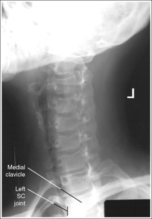
IMAGE 24
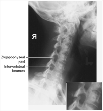
IMAGE 25
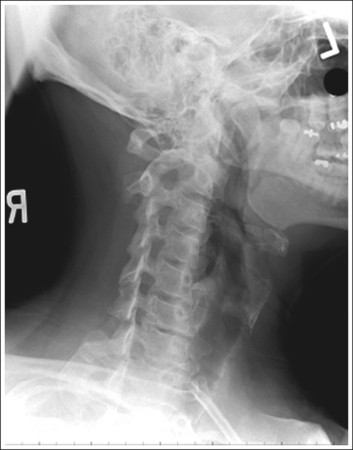
IMAGE 26
• Positioning for trauma. When imaging the cervical vertebrae of a trauma patient with suspected subluxation or fracture, obtain the trauma AP axial and lateral projections and have them evaluated before the patient is moved for the AP axial oblique projection. The trauma AP axial oblique projection of the cervical vertebrae is accomplished by elevating the supine patient's head, neck, and thorax enough to place a lengthwise IR beneath the neck. If the right vertebral foramina and pedicles are of interest, the IR should be shifted to the left enough to align the right mastoid tip with the longitudinal axis of the IR and inferior enough to position the right gonion (C3) with the transverse axis of the IR. Direct the central ray 45 degrees medially to the right side of the patient's neck and 15 degrees cephalically, and then center it halfway between the AP surfaces of the neck at the level of the thyroid cartilage (C4) (Figure 8-20). If the left vertebral foramina and pedicles are of interest, shift the IR to the right enough to align the right mastoid tip with the longitudinal axis of the IR and inferior enough to position the left gonion with the transverse axis of the IR. The central ray should be angled and centered as described earlier, except that it should be directed to the left side of the patient's neck. A trauma AP axial oblique cervical projection should meet all the analysis requirements listed for a regular AP axial oblique cervical projection; the cranium will be in an AP oblique projection (Figure 8-21).
The intervertebral disk spaces are open, the cervical bodies are demonstrated as individual structures and are uniform in shape, and the posterior arch of the atlas is demonstrated without self-superimposition, demonstrating the vertebral foramen. The inferior outline of the outer cranial cortices and the mandibular rami are demonstrated without superimposition.
• The cervical vertebral column demonstrates a lordotic curvature. This curvature, along with the shape of the cervical bodies, causes the disk-articulating surfaces of the vertebral bodies to slant downward posteriorly to anteriorly.
• Importance of central ray angulation. To obtain open intervertebral disk spaces and undistorted, uniformly shaped vertebral bodies, the central ray must be angled in the same direction as the slope of the vertebral bodies. This is accomplished by angling the central ray 15 to 20 degrees caudally for PA axial oblique projections and 15 to 20 degrees cephalically for AP axial oblique projections. This angle will also result in demonstration of the atlas's vertebral foramen on the projections.
• Effect of inaccurate central ray angulation. If the central ray is not accurately angled with the intervertebral disk spaces, they are closed and the cervical bodies are not demonstrated as individual structures (see Images 27 and 28). Because this examination can be performed using AP or PA axial oblique projections that require differing central ray angulations, and the typical cervical vertebral series requires the radiographer to change angle directions several times, radiographers should be able to identify an image that was taken with an incorrect angle. Image 27 was taken using a perpendicular central ray, and Image 28 was taken with the central ray angled in the wrong direction. Note the closed intervertebral disk spaces, distorted cervical bodies, and demonstration of the posterior tubercles within the intervertebral foramina.
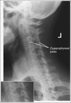
IMAGE 27
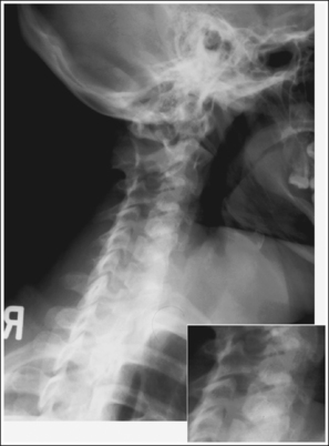
IMAGE 28
• Positioning for kyphosis. In patients with severe kyphosis, the lower cervical vertebrae are angled toward the IR because of the greater lordotic curvature of this area. To demonstrate the lower cervical vertebrae with open intervertebral disk spaces and undistorted cervical bodies, the central ray will need to be angled more than the suggested 15 to 20 degrees for the AP-PA oblique projection. The patient in Image 29 had kyphosis. Note the decrease in intervertebral disk space openness and vertebral body distortion and the demonstration of the zygapophyseal joints through the cervical bodies between the upper and lower cervical regions.
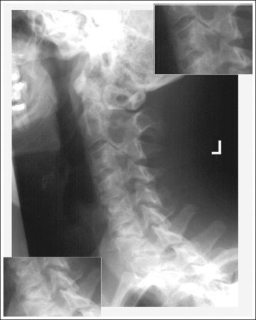
IMAGE 29
• Mandibular rami and cranial demonstration. The distances demonstrated between the inferior cortical outlines of the cranium and the mandibular rami are a result of the angulation placed on the central ray. On PA axial oblique cervical projections, the caudal angle projects the cranial cortex situated farther from the IR approximately 0.25 inch (0.6 cm) inferiorly and the mandibular ramus situated farther from the IR approximately 0.5 inch (1.25 cm) inferiorly. The ramus is projected farther inferiorly because it is located at a larger OID than the cranial cortex. On AP axial oblique projections, the cephalic angle projects the cranial cortex and mandibular rami situated farther from the IR superiorly.
The distance between these two cortical outlines will be increased or decreased if the patient's head is allowed to tilt toward or away from the IR. Such tilting also causes the upper cervical vertebrae to lean toward or away from the IR. To avoid head and cervical column tilting, position the interpupillary line parallel with the floor.
• Detecting head tilting. On PA axial oblique projections, if the head and upper cervical column are allowed to tilt, the atlas and its posterior arch are distorted. From such an image, one can determine whether the head and upper cervical vertebrae were tilted toward or away from the IR by evaluating the distance demonstrated between the inferior cranial cortices and the inferior mandibular rami. If these distances are increased, the head and upper cervical vertebrae were tilted away from the IR (see Image 30). If these distances are decreased, the head and upper cervical vertebrae were tilted toward the IR.
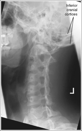
IMAGE 30
The cranium is in an oblique or lateral projection as defined by the facility.
Oblique cranium: The upper cervical vertebrae are demonstrated with posterior occipital and mandibular superimposition (see Figure 8-16).
• The desired position of the patient's head for an AP axial oblique cervical projection varies among facilities. If an AP oblique cranium projection is desired, rotate the patient's head 45 degrees with the body. If a lateral cranium projection is desired, turn the patient's face away from the side of interest until the head's midsagittal plane is aligned parallel with the IR.
Lateral cranium: The upper cervical vertebrae are demonstrated without occipital or mandibular superimposition, and the right and left posterior cortices of the cranium and mandible are aligned (see Figure 8-17).
• To demonstrate the upper cervical vertebrae without mandibular superimposition and aligned right and left cranial and mandibular cortices on an AP axial oblique cervical projection, place the patient's cranium in a lateral projection and adjust chin elevation until the acanthiomeatal line is aligned parallel with the floor. If the patient's chin is not properly elevated and/or the patient's head is rotated, the mandibular rami are superimposed over C1 and C2 (see Image 31).
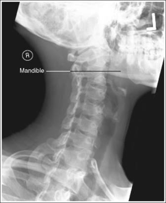
IMAGE 31
The fourth cervical vertebra is centered within the exposure field. The first through seventh cervical vertebrae, the first thoracic vertebra, and the surrounding soft tissue are included within the collimated field.
• Center a 15- to 20-degree cephalically angled central ray for the AP axial oblique or a 15- to 20-degree caudally angled central ray for the PA axial oblique to the patient's midsagittal plane at a level halfway between the EAM and the jugular notch to center C4 to the exposure field.
• Open the longitudinal collimation to the EAM and the jugular notch. Transverse collimation should be to within 0.5 inch (1.25 cm) of the neck skin line.
• An 8- × 10-inch (18- × 24-cm) IR placed lengthwise should be adequate to include all the required anatomic structures.
Posteroanterior Axial Oblique Cervical Vertebrae Projection Analysis
This patient was in a left PA axial oblique projection (anterior oblique [LAO] position), with the head in a PA projection. The pedicles and intervertebral foramina are obscured, and portions of the left sternoclavicular joint and medial clavicular end are superimposed by the vertebral column. The patient was not rotated the required 45 degrees.
Correction
Increase the patient obliquity until the midcoronal plane is placed at a 45-degree angle with the IR.
Analysis
This patient was in a right PA axial oblique projection (anterior oblique [RAO] position), with the patient's head in a lateral projection. The intervertebral foramina are demonstrated, the right pedicles are shown, although they are not in true profile, the left pedicles are demonstrated in the midline of the vertebral bodies, and the right zygapophyseal joints are demonstrated. The patient was rotated more than 45 degrees.
Correction
Decrease the patient rotation until the midcoronal plane is placed at a 45-degree angle with the IR.
Analysis
This patient was in a right PA axial oblique projection (RAO position) with the patient's head in a lateral projection. The upper cervical vertebrae demonstrate open and uniformly shaped intervertebral foramina, and the left pedicles are aligned with the anterior vertebral body, indicating that the patient's upper vertebrae were adequately rotated. The lower cervical vertebrae demonstrate the right zygapophyseal joints, narrowed and distorted intervertebral foramina, and the left pedicles aligned closer toward the midline of the vertebral bodies, indicating that the patient's torso was overrotated.
Correction
While maintaining the degree of upper cervical rotation, decrease patient torso rotation until the midcoronal plane is placed at a 45-degree angle with the IR.
Analysis
This patient was in a left PA axial oblique projection (LAO position), with the head in a lateral projection. The intervertebral disk spaces are closed, the cervical bodies are distorted, the posterior tubercles are demonstrated within the intervertebral foramina, the C1 vertebral foramen is not demonstrated, and the inferior mandibular rami and cranial cortices are demonstrated with superimposition. The central ray was directed perpendicular to the IR.
Analysis
This patient was in a right PA axial oblique projection (RAO position), with the head in a lateral projection. The intervertebral disk spaces are closed, the cervical bodies are distorted, the posterior tubercles are demonstrated within the intervertebral foramina, the C1 intervertebral foramen is demonstrated, and the inferior mandibular rami and cranial cortices are shown without superimposition. The central ray was angled 15 to 20 degrees cephalically.
Analysis
This patient is in a left PA axial oblique projection (LAO position), with the head in a lateral projection. A decrease in intervertebral disk space openness and vertebral body distortion are present, and demonstration of the zygapophyseal joints through the cervical bodies in the lower cervical vertebrae (C5 through C7) is increased. The patient is kyphotic, and the entire cervical spine was not aligned parallel with the IR.
Correction
Align the entire cervical spine parallel with the IR or increase the central ray angulation over the 15 to 20 degrees required for a routine PA axial oblique projection to demonstrate the fifth through seventh cervical vertebrae better.
Analysis
This patient was in a left PA axial oblique projection (LAO position), with the head in a lateral projection. The atlas and its posterior arch are obscured. The inferior cranial cortices demonstrate more than 0.25 inch (0.6 cm) between them, and the inferior cortices of the mandibular rami demonstrate more than 0.5 inch (1.25 cm) between them. The first thoracic vertebra is not included in its entirety. The head and the upper cervical vertebrae were tilted away from the IR, and the central ray and IR were positioned too superiorly.
Correction
Tilt the patient's head toward the IR until the interpupillary line is aligned perpendicular to the IR, and move the central ray and IR inferiorly.
CERVICOTHORACIC VERTEBRAE
CERVICOTHORACIC VERTEBRAE: LATERAL PROJECTION (TWINING METHOD; SWIMMER's TECHNIQUE)
This examination is performed when the routine lateral cervical projection does not adequately demonstrate the seventh cervical vertebra or when the routine lateral thoracic projection does not demonstrate the first through third thoracic vertebrae. See Figure 8-22 and Box 8-6.
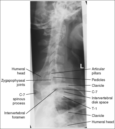
The cervicothoracic vertebrae are demonstrated in a lateral projection. The humerus elevated above the patient's head is aligned with the vertebral column, the right and left cervical zygapophyseal joints and articular pillars are superimposed, and the posterior ribs are superimposed.
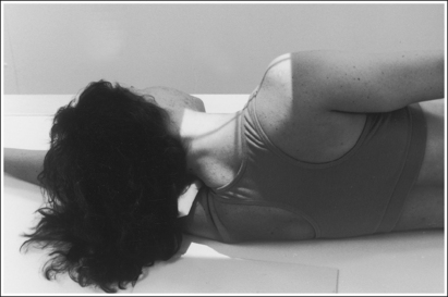
• Position the patient in an upright or a recumbent lateral projection. Whether the right or left side of the patient is positioned against the imaging table or upright IR is not significant, although left-side positioning is easier for the technologist. For the recumbent position, flex the patient's knees and hips for support. For the upright position, instruct the patient to evenly distribute weight on both feet. Elevate the arm positioned closer to the IR above the patient's head as high as the patient allows. The forearm and hand may be rested on the head for support in the erect position. Place the other arm against the patient's side, and instruct the patient to depress this shoulder (Figure 8-23) and move it slightly anteriorly. This supplementary lateral cervicothoracic projection moves the shoulders in opposite directions, overlapping one onto the upper cervical region and the other onto the lower thoracic region, allowing visualization of the cervicothoracic area without shoulder superimposition. To demonstrate the fifth through seventh cervical vertebrae and the first through third thoracic vertebrae without shoulder superimposition, the shoulder positioned away from the IR is depressed. Taking the image on expiration will also aid in lowering the shoulder. A 5-degree caudal central ray angulation may be used for a patient who is unable to depress the shoulder positioned farther from the IR adequately. This angle projects the shoulder inferiorly.
Once the shoulders are positioned, adjust patient head and body rotation to obtain a lateral projection. You can avoid cervical rotation by placing the head in a lateral projection and thoracic rotation by resting your extended flat palm against the patient's shoulders and the inferior posterior ribs, and then adjusting patient rotation until your hand is positioned perpendicular to the imaging table or upright grid holder.
• Detecting rotation. If the patient is rotated, the articular pillars, posterior ribs, zygapophyseal joints, and humeri move away from each other, obscuring the pedicles and distorting the vertebral bodies. When rotation is demonstrated on a lateral cervicothoracic projection, determine which side was rotated anteriorly or posteriorly by evaluating the position of the humeral head positioned closer to the IR. If the patient was rotated anteriorly, the humeral head farther from the IR is positioned anteriorly (see Image 32). If the patient was rotated posteriorly, the humeral head closer to the IR is positioned anteriorly and the humeral head farther from the IR is positioned posteriorly (see Image 33).
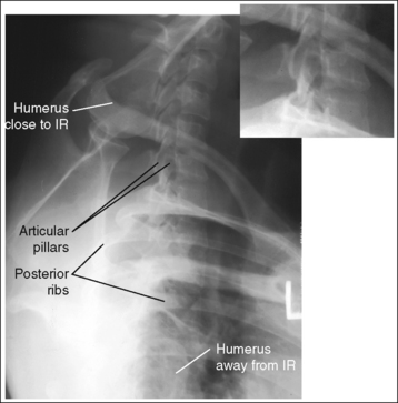
IMAGE 32
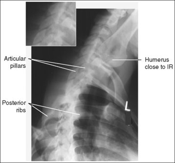
IMAGE 33
• Positioning for trauma. When routine cervical projections are obtained in a trauma patient with suspected subluxation or fracture and the seventh lateral cervical vertebra is not demonstrated, obtain the lateral cervicothoracic projection with the patient's head, neck, and body trunk left as is. Instruct the patient to elevate the arm farther from the x-ray tube and to depress the arm closer to the tube. Then place a grid cassette against the patient's lateral body surface, centering its transverse axis at a level 1 inch (2.5 cm) superior to the jugular notch (Figure 8-24). Position the central ray horizontal to the posterior neck surface and the center of the grid cassette. If the shoulder closer to the central ray is not well depressed, a 5-degree caudal angulation is recommended.
The intervertebral disk spaces are open, and the vertebral bodies are demonstrated without distortion.
• To obtain open disk spaces and undistorted vertebral bodies, position the head in a lateral projection, with the interpupillary line perpendicular to and the midsagittal plane parallel with the upright grid holder or imaging table.
• If the patient is in a recumbent lateral projection, it may be necessary to elevate the head on a sponge to place it in a lateral projection, preventing cervical column tilting (see Image 34).
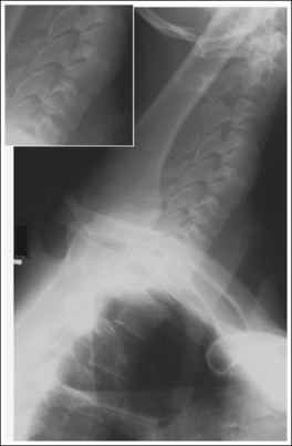
IMAGE 34
The first thoracic vertebra is centered within the exposure field. The fifth through seventh cervical vertebrae and the first through fourth thoracic vertebrae are included within the collimated field.
• Center a perpendicular central ray to the midcoronal plane at a level 1 inch (2.5 cm) superior to the jugular notch or at the level of the vertebral prominens. The seventh cervical vertebra can be identified on a lateral cervicothoracic projection by locating the elevated clavicle, which is normally shown traversing the seventh cervical vertebra.
• Open the longitudinal collimated field to the patient's mandibular angle. Transverse collimation should be to within 0.5 inch (1.25 cm) of the cervical skin line.
• A 10- × 12-inch (24- × 30-cm) IR placed lengthwise should be adequate to include all the required anatomic structures.
Lateral Cervicothoracic Vertebrae Projection Analysis
Analysis: The right and left articular pillars, zygapophyseal joints, and posterior ribs are demonstrated without superimposition. The patient's thorax was rotated. The humerus that was raised and situated closer to the IR is demonstrated posterior to the vertebral column. The shoulder that was depressed and positioned farther from the IR was rotated anteriorly.
Correction: Rotate the shoulder positioned farther from the IR posteriorly, until your flat palms placed against the shoulders or posterior ribs, respectively, are aligned perpendicular to the imaging table and upright grid holder.
Analysis: The right and left articular pillars, zygapophyseal joints, and posterior ribs are demonstrated without superimposition. The patient's thorax was rotated. The humerus that was raised and situated closer to the IR is demonstrated anterior to the vertebral column. The shoulder that was depressed and positioned farther from the IR was rotated posteriorly.
Correction: Rotate the shoulder positioned farther from the IR anteriorly until your flat palms placed against the shoulders and posterior ribs, respectively, are aligned perpendicular to the imaging table and upright IR.
THORACIC VERTEBRAE
THORACIC VERTEBRAE: ANTEROPOSTERIOR PROJECTION
See Figure 8-25 and Box 8-7.
There should be uniform density across the thoracic vertebrae.
• When an exposure (mAs) is set that adequately demonstrates the lower thoracic vertebrae (T6 to T12), the upper thoracic vertebrae (T1 to T5) are often overexposed because of the difference in AP body thickness between these two regions. Two methods may be used to achieve uniform density in spite of this difference in thickness. The first method uses a wedge compensating filter and the second method uses the anode heel effect.
• Wedge filter. The wedge filter absorbs x-ray photons before they reach the patient, thereby decreasing the number of photons exposing the IR where the filter is located (see discussion in Chapter 1). The number of the upper thoracic vertebrae that should be covered by the filter's shadow depends on the slope of the patient's sternum and upper thorax. Position the thin edge of the wedge filter's shadow at the inferior sternum and thorax, at the level at which they begin to decline (Figures 8-26 and 8-27). If the wedge filter has been accurately positioned, there will be uniform image density throughout the thoracic column. If the wedge filter was inaccurately positioned, a definite density difference will define where the wedge filter was and was not placed. Positioning the filter too inferiorly on the patient results in an underexposed area where the filter was misplaced (see Image 35). Positioning the filter too superiorly results in an overexposed area where the filter should have been placed.
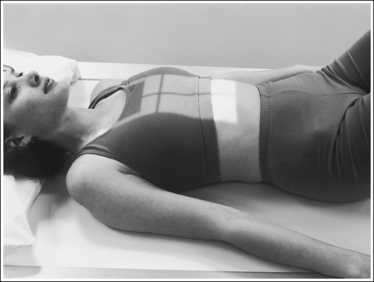
FIGURE 8-26 Proper patient positioning for AP thoracic vertebrae projection with compensating filter.
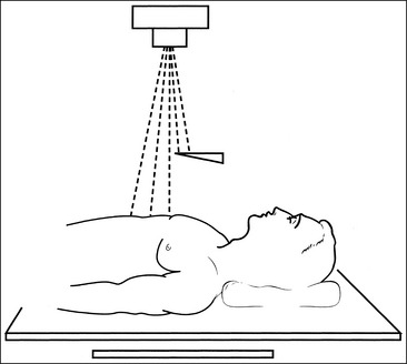
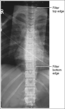
IMAGE 35
• Anode heel effect. The anode heel effect works similarly to a filter; it decreases the number of photons reaching the upper thoracic vertebrae and results in decreased density in this area. This method works sufficiently in patients who have very little difference in AP body thickness between their upper and lower thoracic vertebrae but does not provide an adequate density decrease in patients with larger thickness differences. For the latter patients, use the anode heel effect in combination with a wedge filter. To use the anode heel effect, position the patient's head and upper thoracic vertebrae at the anode end of the tube and the feet and lower thoracic vertebrae at the cathode end. Then set an exposure (mAs) that adequately demonstrates the middle thoracic vertebrae. Because the anode will absorb some of the photons aimed at the anode end of the IR, the upper thoracic vertebrae will receive less exposure than the lower vertebrae.
• Expiration versus inspiration. Patient respiration determines the amount of contrast and density difference demonstrated between the mediastinum and vertebral column. These differences are a result of the variation in atomic density that exists between the thoracic cavity and the vertebrae. The thoracic cavity is largely composed of air, which contains very few atoms in a given area; the same area of bone, as in the vertebrae, contains many compacted atoms. As radiation goes through the patient's body, fewer photons are absorbed in the thoracic cavity than in the vertebral column, because fewer atoms with which the photons can interact are present in the thoracic cavity. Consequently, more photons will penetrate the thoracic cavity to expose the IR than will penetrate the vertebral column. Taking the exposure on full suspended expiration can help decrease the thoracic cavity's image density by reducing the air volume and compressing the tissue in this area (see Figure 8-25). This decreased image density allows better visualization of the posterior ribs and mediastinum region. If the AP thoracic vertebrae projection is exposed while the patient is in full suspended inspiration, the thoracic cavity demonstrates increased image density compared with the vertebral column (see Image 36). It should be noted, however, that the contrast created on an AP thoracic vertebrae projection taken on inspiration can be valuable in detecting thoracic tumors or disease.
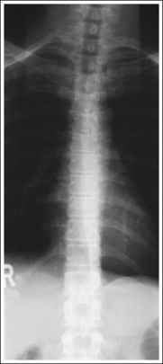
IMAGE 36
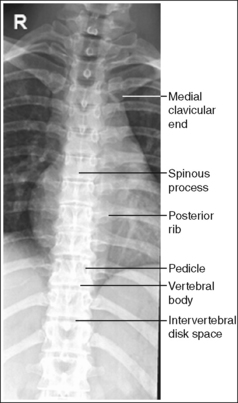
The thoracic vertebral column demonstrates an AP projection. The spinous processes are aligned with the midline of the vertebral bodies, the distances from the vertebral column to the medial (sternal) ends of the clavicles are equal, and the distances from the pedicles to the spinous processes are equal on the two sides.
• An AP thoracic vertebrae projection is obtained by placing the patient supine on the imaging table. Position the shoulders and ASISs at equal distances from the imaging table to prevent rotation, and draw the patient's arms away from the thoracic area to keep them from being tucked beneath the patient (Figure 8-28).
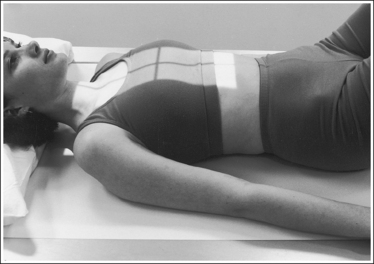
FIGURE 8-28 Proper patient positioning for AP thoracic vertebrae projection without compensating filter.
• Effect of rotation. The upper and lower thoracic vertebrae can demonstrate rotation independently or simultaneously, depending on which section of the body is rotated. If the patient's shoulders and upper thorax were rotated and the pelvis and lower thorax remained supine, the upper thoracic vertebrae demonstrate rotation. If the patient's pelvis and lower thorax were rotated and the thorax and shoulders remained supine, the lower thoracic vertebrae demonstrate rotation. If the patient's thorax and pelvis were rotated simultaneously, the entire thoracic column demonstrates rotation.
• Detecting rotation. Rotation is effectively detected on an AP thoracic projection by comparing the distances between pedicles and spinous processes on the same vertebra and the distances between the vertebral column and medial ends of the clavicles. When no rotation is present, the comparable distances are equal. If one side demonstrates a larger distance, vertebral rotation is present. The side demonstrating a larger distance is the side of the patient positioned closer to the imaging table and the IR (see Image 37).
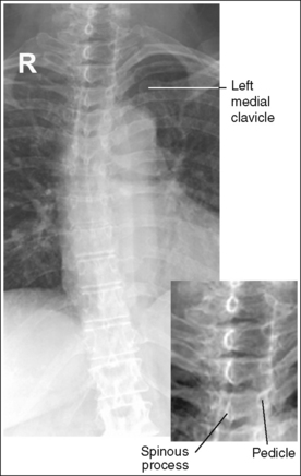
IMAGE 37
• Distinguishing rotation from scoliosis. In patients with spinal scoliosis, the thoracic bodies may appear rotated because of the lateral twisting of the vertebrae. Scoliosis of the vertebral column can be very severe, demonstrating a large amount of lateral deviation, or it can be subtle, demonstrating only a small amount of deviation (Figure 8-29). Severe scoliosis is very obvious and is seldom mistaken for patient rotation, whereas subtle scoliotic changes may be easily mistaken for rotation. Although both conditions demonstrate unequal distances between the pedicles and spinous processes, certain clues can be used to distinguish subtle scoliosis from rotation. The long axis of a rotated vertebral column remains straight, whereas the scoliotic vertebral column demonstrates lateral deviation. When the thoracic vertebrae demonstrate rotation, it has been caused by the rotation of the upper or lower torso. Rotation of the middle thoracolumbar vertebrae does not occur unless the upper and lower thoracic vertebrae also demonstrate rotation. On an image from a patient with scoliosis, the thoracolumbar vertebrae may demonstrate rotation without corresponding upper or lower vertebral rotation. Familiarity with the difference between a rotated thoracic vertebral column and a scoliotic one prevents unnecessarily repeated procedures in patients with spinal scoliosis.
The intervertebral disk spaces are open, and the vertebral bodies are demonstrated without distortion.
• The thoracic vertebral column demonstrates a kyphotic curvature. Because the thoracic vertebrae have very limited flexion and extension movements, it is difficult to achieve a significant reduction of this curvature. A small reduction can be obtained by placing the patient's head on a thin pillow or sponge and flexing the hips and knees until the lower back rests firmly against the imaging table; both procedures improve the relationship of the upper and lower vertebral disk spaces and bodies with the x-ray beam. The head position reduces the upper vertebral curvature, and the hip and knee position reduces the lower vertebral curvature. If the disk spaces are not aligned parallel with the x-ray beam and the vertebral bodies are not aligned perpendicular to the x-ray beam, it is difficult for the reviewer to evaluate the height of the disk spaces and vertebral bodies (see Image 38).
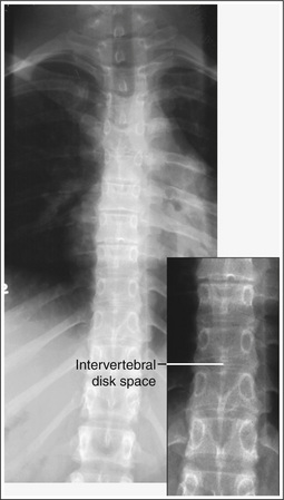
IMAGE 38
• Positioning for kyphosis. To demonstrate open disk spaces and undistorted vertebral bodies in a patient with excessive spinal kyphosis, it may be necessary to angle the central ray until it is perpendicular to the vertebral area of interest. Because it is painful for such a patient to lie supine on the imaging table, it is best to perform the examination with the patient upright or recumbent in a lateral projection with use of a horizontal beam.
The seventh thoracic vertebra is centered within the exposure field. The seventh cervical vertebra, first through twelfth thoracic vertebrae, first lumbar vertebra, and 2.5 inches (6.25 cm) of the posterior ribs and mediastinum on each side of the vertebral column are included within the collimated field.
• Center a perpendicular central ray to the patient's midsagittal plane at a level halfway between the jugular notch and the xiphoid to position the seventh thoracic vertebra in the center of the exposure field.
• Open the longitudinal collimation the full 17-inch (43-cm) IR length for adult patients. Transverse collimation should be to approximately an 8-inch (20-cm) field.
• A 14- × 17-inch (35- × 43-cm) IR placed lengthwise should be adequate to include all the required anatomic structures.
Anteroposterior Thoracic Vertebrae Projection Analysis
Analysis: The sixth through ninth thoracic vertebrae are underexposed. The wedge compensating filter was positioned too inferiorly.
Correction: Position the shadow of the wedge filter's thin edge at the beginning of the downward slope of the patient's sternum and upper thorax, as shown in Figure 8-26.
Correction: Expose the image with the patient in full expiration. If a mediastinal tumor or disease is in question, however, no correction is needed.
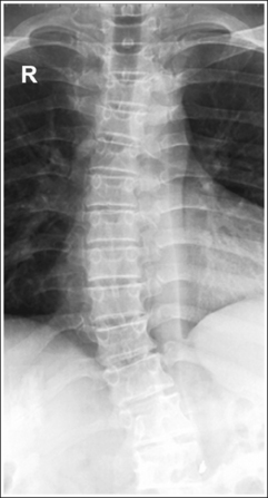
Analysis: The upper cervical vertebrae demonstrate more distance from the left pedicle to the spinous process than from the right pedicle to the spinous process, and the left medial clavicle is demonstrated away from the vertebral column. The patient was rotated toward the left side.
Correction: Rotate the patient toward the right side until the shoulders and ASISs are at equal distances from the imaging table.
THORACIC VERTEBRAE: LATERAL PROJECTION
See Figure 8-30 and Box 8-8.
The thoracic vertebrae are demonstrated through overlying lung and rib structures.
• Breathing technique. The thoracic vertebrae have many overlying structures, including the axillary ribs and lungs. Using a long exposure time (3 to 4 seconds) and requiring the patient to breathe shallowly (costal breathing) during the exposure forces a slow and steady, upward and outward movement of the ribs and lungs. This technique is often referred to as breathing technique. This movement causes blurring of the ribs and lung markings on the image, providing greater thoracic vertebral demonstration. Deep breathing, which requires movement (elevation) of the sternum and a faster and expanded upward and outward movement of the ribs and lungs, should be avoided during the breathing technique, because deep breathing results in motion of the thoracic cavity and vertebrae (see Image 39).
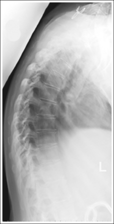
IMAGE 39
• NOTE: If patient motion cannot be avoided when using the extended 3 to 4 seconds for breathing technique, take the image on suspended expiration to reduce the air volume within the thoracic cavity.
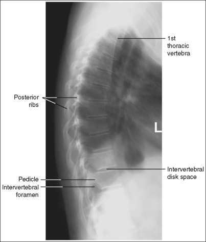
The thoracic vertebrae demonstrate a lateral projection. The intervertebral foramina are clearly demonstrated, the pedicles are in profile, the posterior surfaces of each vertebral body are superimposed, and no more than 0.5 inch (1.25 cm) of space is demonstrated between the posterior ribs.
• To obtain a lateral thoracic vertebrae projection, place the patient on the imaging table in a lateral recumbent projection. Whether the patient is lying on the right or left side is not significant, although left-side positioning is easier for the technologist (Figure 8-31). One exception to this guideline is the scoliotic patient, who should be placed on the imaging table so the central ray is directed into the spinal curve. Abduct the patient's arms to a 90-degree angle with the body to prevent the humeri or their soft tissue from obscuring the thoracic vertebrae. Flex the patient's knees and hips for support, and position a pillow or sponge between the knees. The thickness of the pillow or sponge should be enough to prevent the side of the pelvis situated farther from the IR from rotating anteriorly but not so thick as to cause posterior rotation. To avoid vertebral rotation, align the shoulders, the posterior ribs, and the posterior pelvic wings perpendicular to the imaging table and IR by resting an extended flat palm against each, respectively, and then adjusting patient rotation until the hand is positioned perpendicular to the IR.
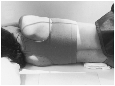
• Effect of rotation. The upper and lower thoracic vertebrae can demonstrate rotation independently or simultaneously, depending on which section of the torso was rotated. If the shoulders and the superoposterior ribs were not placed on top of each other but the posterior pelvic wings and inferoposterior ribs were aligned, the upper thoracic vertebrae demonstrate rotation and the lower thoracic vertebrae demonstrate a true lateral projection. If the posterior pelvic wings and inferoposterior ribs were rotated but the shoulders and superoposterior ribs were placed on top of each other, the lower thoracic vertebrae demonstrate rotation and the upper vertebrae demonstrate a lateral projection.
• Detecting rotation. Rotation can be detected on a lateral thoracic vertebrae projection by evaluating the superimposition of the right and left posterior surfaces of the vertebral bodies and the amount of posterior rib superimposition. On a nonrotated lateral thoracic projection, the posterior surfaces are superimposed and the posterior ribs are almost superimposed. Because the posterior ribs positioned farther from the IR were placed at a greater OID than the other side, they demonstrate more magnification. This magnification prevents the posterior ribs from being directly superimposed but positions them approximately 0.5 inch (1.25 cm) apart. This distance is based on a 40-inch (102-cm) SID. If a longer SID is used, the distance between the posterior ribs is decreased and, if a shorter SID is used, the distance is increased. On rotation, the right and left posterior surfaces of the vertebral bodies are demonstrated one anterior to the other on a lateral projection.
Because the two sides of the thorax and vertebrae are mirror images, it is very difficult to determine from a rotated lateral thoracic projection which side of the patient was rotated anteriorly and which posteriorly. If the patient was only slightly rotated, one way of determining which way the patient was rotated is to evaluate the amount of posterior rib superimposition. If the patient's elevated side was rotated posteriorly, the posterior ribs demonstrate more than 0.5 inch (1.25 cm) of space between them (see Image 40). If the patient's elevated side was rotated anteriorly, the posterior ribs are superimposed on slight rotation (see Image 41) and demonstrate greater separation as rotation of the patient increases. Another method is to view the scapulae and humeral heads when visible. The scapula and humeral head demonstrating the greatest magnification will be the ones situated farthest from the IR (see Image 42).
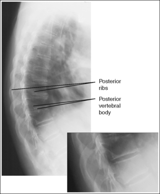
IMAGE 40
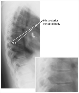
IMAGE 41
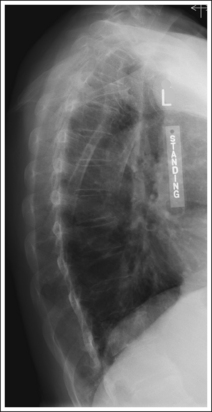
IMAGE 42
• Distinguishing rotation from scoliosis: On the image of a patient with spinal scoliosis, the lung field may appear rotated because of the lateral deviation of the vertebral column (see Image 12, Chapter 3). On such an image, the posterior ribs demonstrate differing degrees of separation depending on the severity of the scoliosis. View the accompanying AP thoracic projection (see Image 3, Chapter 3) to confirm this patient condition.
The intervertebral disk spaces are open, and the vertebral bodies are demonstrated without distortion.
• The thoracic vertebral column is capable of lateral flexion. When the patient is placed in a recumbent lateral projection, the vertebral column may not be aligned parallel with the imaging table and IR but may sag at the level of the lower thoracic vertebrae, especially in a patient who has wide hips and a narrow waist (Figure 8-32). If the patient's thoracic column is allowed to sag, the diverging x-ray beams are not aligned parallel with the intervertebral disk spaces and perpendicular with the vertebral bodies. Lateral flexion on a lateral thoracic vertebrae projection is most evident at the lower thoracic vertebral bodies, where closed disk spaces and distorted vertebral bodies are present (see Image 43). For a patient who has a sagging thoracic column, it may be necessary to tuck an immobilization device between the lateral body surface and imaging table just superior to the iliac crest, elevating the sagging area. The radiolucent sponge should be thick enough to bring the thoracic vertebral column parallel with the imaging table and IR (see Figure 8-31)
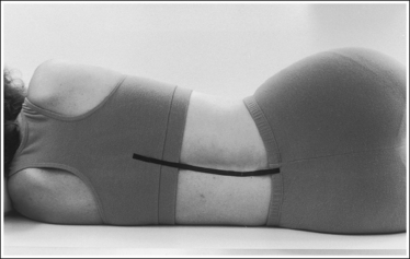
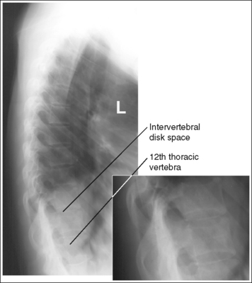
IMAGE 43
• An alternative method of obtaining open disk spaces and undistorted vertebral bodies in a patient whose thoracic column is sagging is to angle the central ray 10 degrees cephalically for female patients and 15 degrees for male patients. The degree of cephalic angulation used should align the central ray perpendicular to the thoracic vertebral column.
The seventh thoracic vertebra is centered within the exposure field. The seventh cervical vertebra, the first through 12th thoracic vertebrae, and the first lumbar vertebra are included within the collimated field.
• Center a perpendicular central ray to the inferior scapular angle. With the patient's arm positioned at a 90-degree angle with the body, the inferior scapular angle is placed over the seventh thoracic vertebra.
• Open the longitudinal collimation the full 17-inch (43-cm) IR length for adult patients. Transverse collimation should be to an 8-inch (20-cm) field.
• A 14- × 17-inch (35- × 43-cm) IR placed lengthwise should be adequate to include all the required anatomic structures.
• Verifying inclusion of all thoracic vertebrae. When viewing a lateral thoracic projection, you can be sure that the twelfth thoracic vertebra has been included by locating the vertebra that has the last rib attached to it; this is the twelfth vertebra. To confirm this finding, follow the posterior vertebral bodies of the lower thoracic and upper lumbar vertebrae, watching for the subtle change in curvature from kyphotic to lordotic. The twelfth thoracic vertebra is located just above it. The first thoracic vertebra can be identified on a lateral thoracic projection by counting up from the twelfth thoracic vertebra or by locating the seventh cervical vertebral prominens. The first thoracic vertebra is at the same level as this prominens.
• Lateral cervicothoracic projection (Twining method). Because of shoulder thickness and the superimposition of the shoulders over the first through third thoracic vertebrae, it may be necessary to take a supplementary image of this area to demonstrate the thoracic vertebrae. Refer to page 449 for details.
Lateral Thoracic Vertebrae Projection Analysis
The thoracic vertebrae, ribs, and lung markings demonstrate a blurring of the recorded details. The image was exposed using deep breathing technique during the exposure, causing patient motion.
Correction
Instruct the patient to breath shallowly. If the patient is unable to perform costal breathing, take the exposure on suspended expiration.
Analysis
The posterior surfaces of the vertebral bodies are demonstrated without superimposition, and more than 0.5 inch (1.25 cm) of space is demonstrated between the posterior ribs. The elevated side of the thorax was rotated posteriorly.
Correction
Rotate the elevated thorax anteriorly until a flat palm placed against the shoulders, posterior ribs, and posterior pelvic wings is aligned perpendicular to the imaging table. All three areas need to be checked to prevent rotation across the entire spine. The amount of rotation required is half the distance demonstrated between the posterior surfaces of the vertebral bodies.
Analysis
The posterior surfaces of the vertebral bodies are demonstrated without superimposition, and the posterior ribs are superimposed. The elevated side of the thorax was rotated anteriorly.
Correction
Rotate the elevated thorax posteriorly until a flat palm placed against the shoulder, posterior ribs, and posterior pelvic wings is aligned perpendicular to the imaging table. The amount of rotation required is half the distance demonstrated between the posterior surfaces of the vertebral bodies.
Analysis
The posterior surfaces of the vertebral bodies are demonstrated without superimposition, more than 0.5 inch (1.25 cm) of space is demonstrated between the posterior ribs, and the more magnified (right side) scapula and humeral head is positioned posterior to the less magnified (left side) scapula and humeral head. The elevated side of the thorax was rotated posteriorly.
Correction
Rotate the elevated thorax anteriorly until a flat palm placed against the shoulder, posterior ribs, and posterior pelvic wings is aligned perpendicular to the imaging table.
Analysis
The T8 through T12 intervertebral disk spaces are obscured, and the vertebral bodies are distorted. The thoracic vertebral column was not aligned parallel with the imaging table.
Correction
Position a radiolucent sponge between the lateral body surface and imaging table just superior to the iliac crest. The radiolucent sponge should be thick enough to align the thoracic vertebral column parallel with the imaging table. If a sponge cannot be used, the central ray can be angled cephalically until it is perpendicular to the thoracic vertebral column.