Chapter 9 Artifacts
An ultrasound artifact is a structure in an image which does not directly correlate with actual tissue being scanned. Artifacts assume different forms, including:
Where an operator is not aware of the presence of artifacts, it is possible that pathology will not be demonstrated and will therefore not be diagnosed (false negative result), or that pathology will be diagnosed where it does not exist (false positive result).
Understanding the basic mechanisms behind ultrasound artifacts, recognizing situations in which they are likely to arise, and becoming familiar with their appearance all help to eliminate misdiagnoses that may otherwise occur.
ASSUMPTIONS MADE BY ULTRASOUND EQUIPMENT
Ultrasound machines have to make certain assumptions in order to operate. These are:
These assumptions are often incorrect and will give rise to appearances which do not correspond to actual anatomy or tissue in the scan plane. It is these appearances that we term artifacts.
Several possible artifactual appearances may occur:
There are a multitude of different artifacts which may occur, but the more commonly occurring artifacts which will be discussed in this chapter are:
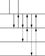
REVERBERATION
This is the production of spurious (false) echoes due to repeated reflections between two interfaces with a high acoustic impedance mismatch. The echo from the interface is received by the transducer and displayed on the image. Some of the energy in the returned echo is reflected at the transducer face, and returns to the reflecting interface as if it was a weak transmitted pulse, returning as a second echo (reverberation). As the time taken for the second echo to arrive is twice that taken by the first echo, the image will display it at twice the depth. This sequence of reflection and transmission can occur many times, with the third echo taking three times as long to return to the transducer and being displayed at three times the depth, and so on. The reverberation echoes will be equally spaced because the time for each additional echo is a multiple of the time of return of the first echo. These reverberation echoes will be strong because of the high acoustic mismatch (see Fig. 9.1).
This artifact will often be seen:
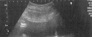
Fig. 9.4 Reverberation occurring between bowel gas and transducer, appearing in the image distal to the bowel gas, and known as ringdown
The artifact can be differentiated from real echoes due to the lack of breathing movement occurring.
ACOUSTIC SHADOWING
This appears as an area of low amplitude echoes (hypoechoic or anechoic) behind an area of strongly attenuating tissue. It is caused by severe attenuation of the beam at an interface, resulting in very little sound being transmitted beyond (see Fig. 9.5). The attenuation can be due to either absorption or reflection of the sound waves, or a combination of the two.
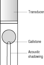
Acoustic shadowing will occur at interfaces with a large acoustic mismatch such as:
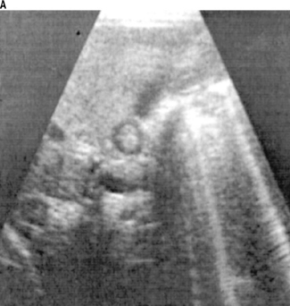
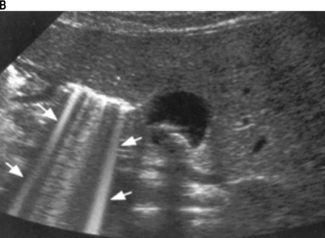
It is often possible to differentiate diagnostically between structures such as gas in the duodenum or calculi in a small contracted gallbladder, by looking at the type of acoustic shadowing. Often shadowing in this area can be ambiguous and lead to an inaccurate diagnosis, but careful examination will reveal different types of shadowing. If the shadowing contains reverberation (ringdown) echoes, it is likely to be gas (see Fig. 9.6a & b). If the shadowing is clear shadowing, absent of any ringdown, it is likely to be a calculus (see Fig. 9.7 a & b).
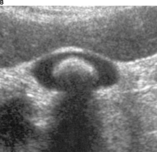
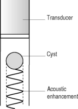
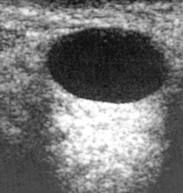
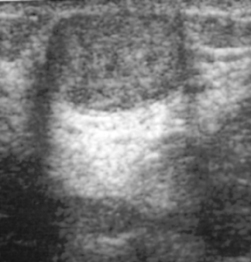
ACOUSTIC ENHANCEMENT
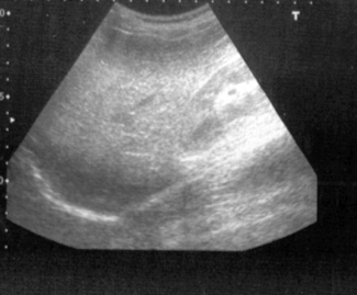
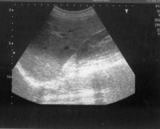
This artifact appears as a localized area of increased echo amplitude behind an area of low attenuation. On a scan it will appear as an area of increased brightness, and can commonly be seen distal to fluid-filled structures such as the urinary bladder, the gallbladder, or a cyst.
The artifact arises due to the application of the time-gain compensation (TGC) to areas of low attenuating structures such as fluid. It is caused by the low level of attenuation of the beam as it passes through fluid relative to the greater attenuation of the beam in the adjacent more solid tissue (see Fig. 9.8). As the echoes pass beyond the area, they will be of higher amplitude than the surrounding tissue because they have been amplified unnecessarily. The high amplitude brightness therefore does not relate to any inherent scattering or reflectivity properties of the tissue, but arises because the equipment assumes a uniform rate of attenuation across the entire image (see Fig. 9.9).
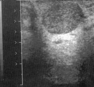
This artifact can often be a useful diagnostic aid, particularly when scanning a soft-tissue mass or cyst containing low-level echoes. These echoes may often cause the structure to disappear in the image as it blends into the surrounding echo pattern. The observant operator will often notice the echo enhancement, resulting in a closer examination of the area above this, and the mass or cyst will then be delineated (see Fig. 9.10).
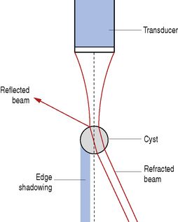
EDGE SHADOWING
A combination of refraction and reflection occurring at the edges of rounded structures (and when the speed of sound is different from that in surrounding tissue) will result in an edge shadowing artifact.
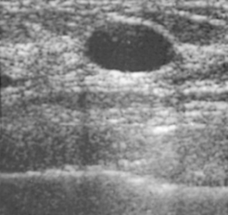
Edge shadowing arises due to refraction of the beam caused by both the curvature of the rounded edges and the difference in speed of the two materials. When the ultrasound beam reaches the rounded edge of a structure, reflection will occur, with the angle of incidence equal to the angle of reflection. The outer part of the beam will be totally reflected, but the remainder of the beam passes through the rounded structure and is refracted (deviated from its original path) (see Fig. 9.11). This combination of reflection and refraction of the beam at the edge of a rounded structure results in a thin strip of tissue behind the edge not being insonated and causes a shadow. These shadows are narrow and occur directly distal to the margins of the rounded structure, such as either a cyst (see Fig. 9.12) or a soft-tissue mass (see Fig. 9.13). The shadowing should normally be readily identified as an artifact, however it is possible that it may be falsely diagnosed as areas of calcification within an organ.
BEAM WIDTH ARTIFACT
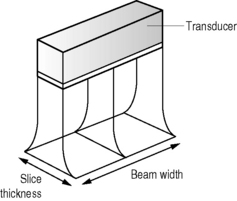
All the echoes returning to the transducer will have arisen from across the full width of the beam, which can vary by several millimeters. As the beam sweeps through the patient, a point reflector will generate an echo for as long as it remains in the beam, and the reflector will be represented as a line in the display rather than a dot. The length of the line will therefore represent the beam width at that depth. This artifact can be demonstrated by scanning a point reflector in a phantom, where the display will clearly portray this as a line (Fig. 9.14).
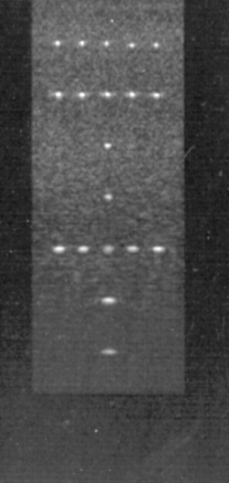
Fig. 9.14 Scan of a phantom demonstrating that the point reflectors can be seen as points in the center of the image where the focal zone is set (and the beam is therefore narrowest), but the same points appear as lines where they lie outside the focal zone (and the beam is wider)
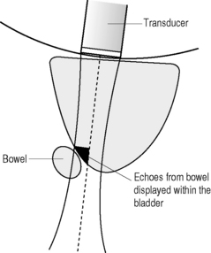
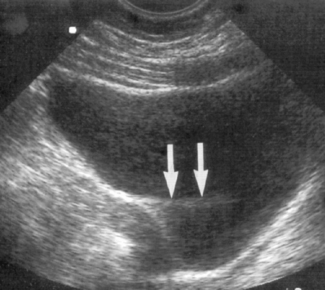
During routine scanning, the artifact can be seen when spurious echoes are displayed in an echo-free area, for example when reflections from bowel are generated by the edge of the beam and displayed inside the sagittal view of the urinary bladder, where the center of the beam is (see Figs 9.15 & 9.16).
Correct positioning of the focal zone will help to reduce this artifact. The focal zone is controlled by electronically narrowing the beam (see Chapter 5 on The ultrasound beam).
SLICE THICKNESS ARTIFACT
These occur due to the thickness of the beam, and are similar to beam width artifacts (see Chapter 5 on The ultrasound beam). However, they occur at 90° to the scan plane (see Fig. 9.17), with echoes from interfaces in front of and behind the assumed plane of origin appearing in the display.
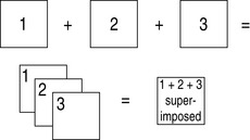
It is assumed that the echoes detected by the transducer are from a very thin slice of tissue. However, the reality is that this slice is actually composed of several slices of information and therefore echoes from interfaces on either side of the intended thin slice will be included in the displayed image (see Fig. 9.18). Increasing the slice thickness will increase the number of artifactual echoes in the display.
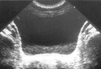
These artifacts will typically be seen in transverse views of the urinary bladder when structures adjacent to the slice through the bladder being scanned will be incorporated into the image. These echoes are then displayed as if they were arising from within the bladder (see Fig. 9.19). Although the appearance of this artifact is similar to the beam width artifact, the differentiating factor is that the reflector causing the slice thickness artifact will not be seen on the display.
This artifact is a result of inherent characteristics of the transducer, and apart from trying a different transducer, cannot be eliminated. New technology, however, is continuously resulting in narrower slice thicknesses.
SIDE LOBE ARTIFACT
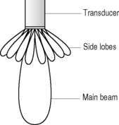
The energy within the ultrasound beam exists as several side lobes radiating at a number of angles from a central lobe (see Fig. 9.20). Echoes are generated by these side lobes in addition to the main lobe, but all the returning echoes are assumed by the transducer to have arisen from the central axis of the main lobe (see Chapter 5 on The ultrasound beam). Side lobe echoes will therefore be misregistered in the display. Because ultrasound beams are three-dimensional, side lobes exist not only in the scan plane but also in the entire 360° around the beam. The echoes generated by the side lobes are usually much lower in amplitude than the main beam and will therefore often not be seen, unless the echoes are returning from a strong reflector such as gas.
This artifact can often be seen in areas such as the urinary bladder where the side lobes detect echoes from adjacent bowel and the equipment registers these echoes as if they have arisen from within the bladder. They may also arise within a cyst, where adjacent structures are portrayed as if arising from within the cyst (see Fig. 9.21). These appearances can give rise to a false diagnosis of septations within a cyst.
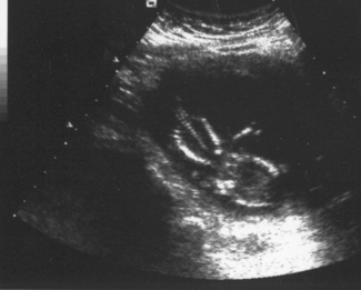
MIRROR IMAGE ARTIFACT
These artifacts result in a mirror image of a structure occurring in an ultrasound display. They arise due to specular reflection of the beam at a large smooth interface. An area close to a specular reflector will be imaged twice, once by the original ultrasound beam and once by the beam after it has reflected off the specular reflector. Echoes return along the same path from the reflecting interface, back to the transducer. Because the equipment assumes all echoes arise from a straight beam, the reflected echoes are displayed in a line as if originating from below the specular reflecting surface (see Fig. 9.22).
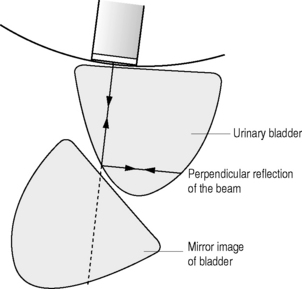
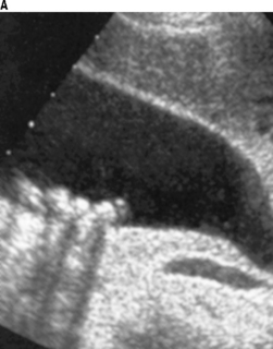
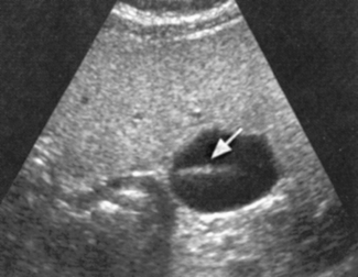
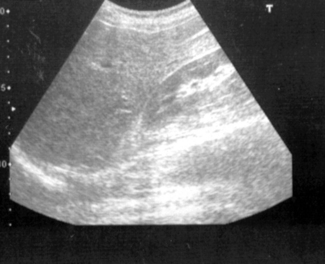
Mirror image artifacts are most commonly seen where there is a large acoustic mismatch, such as a fluid–air interface. Typically this artifact can occur during the scanning of a full urinary bladder, when air in the rectum behind the bladder acts as a specular reflector and a mirror image of the bladder is displayed posteriorly. It will then have the appearance of a large cyst behind the bladder (see Fig. 9.23). It can also be seen when scanning the liver, and the diaphragm acts as a specular reflector. In this case the liver parenchyma is displayed not only below the diaphragm but also above it (see Fig. 9.24). When trying to determine whether these appearances represent pathology or artifact, it is important to recognize whether the echoes have the same appearance as the organ from which they have arisen.
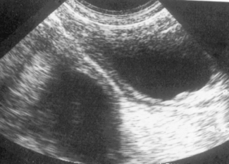
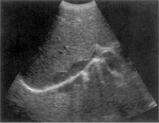
Fig. 9.24 Mirror image artifact of the liver appearing above the diaphragm
(From Bates 1999, with permission of Churchill Livingstone.)
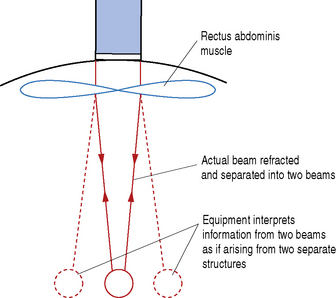
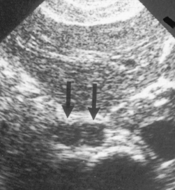
DOUBLE IMAGE ARTIFACT
This artifact is caused by refraction of the beam and may occur in areas such as the rectus abdominis muscle on the anterior abdominal wall. In the transverse plane the edges of the muscle act as a lens and cause the ultrasound beam to be refracted (i.e. deviated from its original path) and this causes a single structure to be interrogated by two separate refracted beams (see Fig. 9.25). Two sets of echoes will therefore be returned and these will cause display of two structures in the image. This results in, for example, two images of the transverse aorta side by side in the abdomen (see Fig. 9.26). Alternatively, a single gestation sac can be mirrored and appear as two gestation sacs side by side, leading to the erroneous diagnosis of a twin pregnancy. In order to establish whether these echoes are genuine, it is necessary to move the transducer slightly to one side to avoid the junction of the rectus abdominis muscles.
EQUIPMENT-GENERATED ARTIFACTS
Incorrect use of the equipment controls can lead to artifacts appearing. Misuse of controls such as the gain (see Fig. 9.27) or TGC (see Figs 9.28 & 9.29) can result in echoes being recorded as too bright or too dark. Care must be taken when setting these controls, to ensure an even brightness throughout the image. If too much gain is applied then the electronic noise, inherent in all systems, will also be amplified. This has the appearance of a fine overlay of low-level echoes in the image and will cause deterioration of the quality of the image, reducing the ability of the operator to correctly interpret. If too little gain is applied, this can lead to loss of relevant information, and incorrect diagnosis may occur.
If the dynamic range control is incorrectly set, this can lead to an image which has too much contrast, and result in the loss of subtle echo information (see Fig. 9.30).
Blurring of a moving image can occur if the frame rate is too low or if the persistence is too high. It is important to ensure that the frame rate is capable of recording a moving structure at the correct speed.
Use of multiple focal zones can give rise to a prominent banding effect within the image. These are usually identifiable as being of electronic origin due to the well-defined margin of the bands.