Chapter 5 The ultrasound beam
BEAM SHAPE
The area through which the sound energy emitted from the ultrasound transducer travels is known as the ultrasound beam. The beam is three-dimensional and is symmetrical around its central axis. It can be subdivided into two regions: a near field (or Fresnel zone) which is cylindrical in shape, and a far field (or Fraunhofer zone) where it diverges and becomes cone-shaped (see Fig. 5.1).
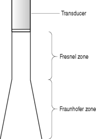
The actual shape of the beam depends on a number of factors, including the diameter of the crystal, the frequency and wavelength, the design of the transducer, and the amount of focusing applied to the beam. Increasing the frequency will result in a longer near field and less far field divergence. A narrow crystal diameter will result in a narrower beam in the near field, but the disadvantage is that the near field is shorter and there is more divergence in the far field.
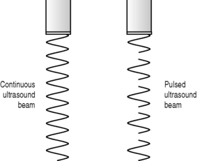
Where there is continuous sound output from a transducer (primarily Doppler applications), there will be sound energy present throughout the beam for the duration of the scanning period. Most diagnostic applications, however, use pulsed sound, where the output is a series of short pulses of sound. In this case sound energy is not present throughout the beam, but only in small areas or pockets. It is the movement of these pockets of sound which we refer to as the ultrasound beam (see Fig. 5.2).
INTENSITY OF THE BEAM
The intensity of the beam is the power (measured in watts) flowing through a unit area (see Chapter 12 on Ultrasound safety). The intensity is not uniform throughout the beam’s length nor across its width. This is caused by a number of variable factors such as:
One noticeable result of the non-uniformity of intensity in the beam is that during scanning, a small reflector will give rise to a stronger echo if it is in the center of the beam (where there is maximum intensity of energy) than if it is on the periphery. This can therefore lead to a false interpretation by the operator as to the density of the reflector.
Where the beam is focused to improve spatial resolution, this will cause further non-uniformity of intensity, because a narrower beam will be created within the area known as the focal zone. The intensity is greatest in the focal zone and therefore a stronger echo will be received from a given structure that lies within the focal zone.
SIDE LOBES
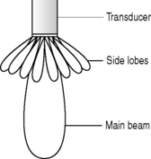
Some of the energy from the transducer radiates at various angles to the transducer face, and these are known as side lobes. There may be one or more of these, and each of them will also be three-dimensional and will be the same frequency as the main lobe (see Fig. 5.3). Any interfaces encountered by any of these side lobes will return echoes to the transducer, which the equipment erroneously assumes to have been received by the main beam. These echoes will therefore be incorrectly placed (or misregistered) on the image (see Chapter 9 on Artifacts). Approximately 15% of the energy in the beam will be within the side lobes. Manufacturers continually attempt to limit the amount of side lobes but are unable to eliminate them completely.
Array transducers will, in addition to the side lobes, also have grating lobes, which are lobes at various angles to the main beam. These only exist in the direction along which there are multiple elements within the array. Both side lobes and grating lobes can lead to considerable artifacts due to the three-dimensional misregistration which inevitably occurs. In addition, they cause a degradation of lateral resolution due to the effective widening of the beam in the scan plane.
BEAM WIDTH
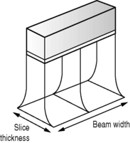
Beam width refers to the dimension of the beam in the scan plane, or the plane through which the beam is sweeping (see Fig. 5.4). The actual beam width will vary according to the distance from the transducer, particularly where focusing is used. The width of each pulse of sound will therefore change with depth. The beam width affects the spatial resolution of the image (the ability of the operator to distinguish small structures) and generally, the narrower the beam width, the better the spatial resolution.
SLICE THICKNESS
The ultrasound image viewed on the monitor is a three-dimensional volume displayed as a two-dimensional image. The slice thickness refers to the dimension of the beam at 90° to the scan plane (see Fig. 5.4). Where the transducer has a circular crystal aperture, because the beam is symmetrical about its central axis, at any distance from the transducer, the beam width and slice thickness are equal. However, where transducers have rectangular apertures (phased array or linear array) the beam width and slice thickness can be very different. The slice thickness is usually larger than the beam width and cannot easily be reduced.
The fact that the beam width and the slice thickness are not finite results in artifacts occurring in the image (see Chapter 9 on Artifacts).
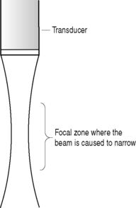
FOCUSING THE BEAM
The ultrasound beam can be focused, during both transmit and receive, to improve the quality within a particular zone of the image. This can be carried out in a number of ways (see Chapter 6 on Transducers) but the objective is to cause the beam to converge, which results in a narrowing of the beam (see Fig. 5.5). The operator can alter the depth of the focal zone or the number of focal zones. Increasing the number of focal zones will increase the size of the area with improved resolution, but will result in a slower frame rate of the image and poor temporal resolution (ability to visualize moving structures).
THE BEAM FORMER
An array transducer has multiple crystal elements (up to 128) and each has its own electrical connection to transmit the beam and receive the echoes. By manipulating the sequence of firing of these elements, the direction of propagation of the beam can be altered. This process is controlled by the beam former which can be manipulated by the operator. The beam former will control a variety of functions such as the focusing, beam steering, and switching between B mode and Doppler (see Chapter 6 on Transducers).