Chapter 13 Quality assurance and performance testing
INTRODUCTION
This chapter provides the reader with a general overview of quality assurance (QA) and performance testing of diagnostic ultrasound equipment. Performance testing of pulse-echo imaging systems will be covered, however because the evaluation of Doppler systems is technically more difficult and is normally performed by specialized medical physicists, it will not be included in this chapter.
QUALITY ASSURANCE
QA is the process of ensuring that all aspects of an ultrasound service meet and perform to agreed standards. The aim of QA is to maintain standards, and to seek to improve the performance of all aspects of an ultrasound service. QA is an essential aspect of clinical governance as it is a risk management tool for ensuring minimum standards of practice and performance are attained. This provides reassurance that all patients have access to high-quality ultrasound services wherever they are.
A comprehensive quality assurance programme should consider:
The quality of the diagnostic investigation and patient service will be affected by factors such as operator training/competence and reporting procedures. These aspects will not be discussed here as this section will concentrate on the quality of image production specifically relating to the QA assessment and performance testing of diagnostic ultrasound machines.
While performance testing in X-ray modalities is almost universally practiced, in ultrasound, performance testing remains somewhat controversial for reasons which include:
There are currently recommendations from the UK Department of Health and guidance from national and international bodies (such as the Institute of Physics and Engineering in Medicine and the American Institute of Ultrasound in Medicine) (see references) as to suggested measures and methods for QA testing. In the UK, only one clinical application, breast ultrasound imaging, has any formal mandatory requirements for the QA performance testing of ultrasound scanning equipment.
QUALITY ASSURANCE TESTING
Equipment Performance Testing
Ultrasound images are formed by transmitting and receiving ultrasound signals which are then processed by a number of individual components within an ultrasound machine. These components have different operations to perform before producing the images that we see on screen.
The accuracy with which the ultrasound image represents the anatomical area under investigation depends on the correct operation of these components and the accuracy of the various signal and image processing functions.
Many faults which can develop on ultrasound scanning equipment are not obvious to the user and gradual changes in performance are especially difficult to detect. Quantifiable assessment of a system’s performance is therefore required to detect any deterioration at an early stage.
The performance assessment and QA of diagnostic ultrasound scanners can also help to:
Ultrasound QA testing should provide objective, accurate, and repeatable measurement of the image displayed on the ultrasound screen, i.e. as seen by the operators. To be successful, QA testing should be easy to implement, simple to use, and able to detect faults at an early stage. It requires the use of strict protocols and documentation in order to ensure standardization of procedures.
In the UK, the Institute of Physics and Engineering in Medicine (IPEM) has produced guidelines for the routine QA of ultrasound imaging systems (Price 1995). The IPEM report advocates three levels of QA testing:
Baseline acceptance tests
These tests should be carried out with any new machine and whenever a new probe or major hardware or software upgrade is added. Typically, it is carried out by a member of the medical physics department. It includes all the tests specified for routine QA, and establishes baseline readings for which further routine and user tests can be compared.
User tests
These are to be carried out at frequent intervals (between 1 to 4 weeks) by the operator, in order to discover any significant changes in scanner performance over time. It includes a number of simple tests which require a minimum amount of time to carry out. These tests relate to the aspects of the scanner function on which users depend for clinically meaningful results and include simple checks, such as testing caliper accuracy.
Routine QA tests
These are to be carried out by a third party, typically by a member of the medical physics department or possibly by a service engineer. They should be performed ideally every 6 months but at least every 12 months. These include a full range of tests which have relevance to normal clinical use and which are likely to detect deterioration in performance.
Equipment Required for Image Performance Testing
Tissue equivalent (TE) phantoms
There are a number of commercially available ultrasound devices that can be used to test whether an ultrasound system is operating correctly and consistently over time. These devices, known as test phantoms, are designed to have similar acoustic characteristics to those of soft tissue and should ideally be composed of material which allows:
The tissue-like attenuation and echogenicity of tissue equivalent phantoms allows the testing of ultrasound systems using actual clinical settings.
Commercially available test phantoms are normally filled with an aqueous gel or are formed from urethane materials. They contain various targets and structures designed for testing a number of parameters. Examples of some commercially available test phantoms are illustrated in Figure 13.1.

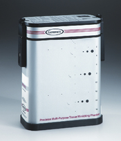
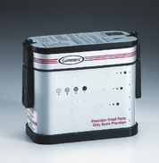
Fig. 13.1 Examples of some commercially available test phantoms used for ultrasound QA performance testing
(Reproduced with permission of Gammex.)
Gel-based tissue equivalent phantoms consist of a closed container filled with an aqueous gel material loaded with graphite particles. These are designed to scatter ultrasound and produce an image that is similar to soft tissue, typically that of the liver. These phantoms have all the required acoustic characteristics matched for soft tissue as indicated above. The main disadvantage with this type of gel-filled phantom is that there is a tendency for the gel to dry out over time which potentially could change the tissue equivalent acoustic properties.
Polyurethane rubber-based phantoms, in comparison, are very stable and do not need to be totally enclosed to avoid them drying out. They can be made to have similar attenuation and scattering properties of soft tissue but have one distinct disadvantage in that the speed of sound is slower, 1450 ms−1 compared to 1540 ms−1 which an ultrasound machine is calibrated to. This discrepancy amounts to a 6–7% propagation speed error and becomes significant when testing caliper accuracy. The manufacturers have attempted to compensate for this by altering the position and distance of the internal targets within the phantom (positioning them closer together) so that these urethane phantoms can be used to test caliper measurements accurately.
Test phantoms contain a variety of structures and targets which can be used to test a range of imaging parameters. Figure 13.2 shows a typical arrangement of targets and structures for a general purpose test phantom. They contain groups of small nylon wires which can be used to measure image resolution and test distance accuracy. They also contain structures of varying sizes to mimic simple cysts. Some have structures which represent more complicated cysts designed to have a range of scattering patterns compared to the background tissue equivalent medium in order to assess contrast resolution and estimate the dynamic range.
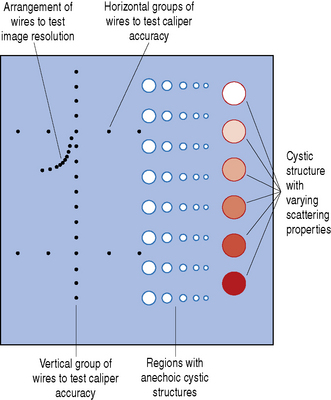
Fig. 13.2 Typical arrangement of nylon wire targets, simple and complex cysts with a range of scattering properties within a general purpose test phantom
Ultrasound images are formed using a variety of different transducers which operate over a range of frequencies and depths. Therefore ultrasound phantoms come in various shapes and sizes to accommodate this. If a low-frequency transducer is to be tested (2–5 MHz) then the test phantom will need to be relatively large and typically will need to be around 15 cm deep. For higher frequency transducers (7 MHz–12 MHz), where the beam is less penetrating but the images have improved resolution, then a smaller phantom is required with smaller structures to be able to assess and measure this. Two test phantoms which are designed for high- and low-frequency transducer applications can be seen in Figure 13.3.
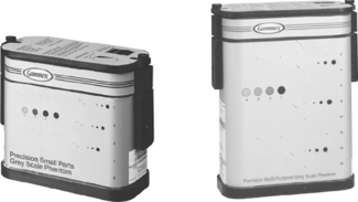
Fig. 13.3 Two multi-purpose test phantoms. The larger phantom on the right-hand side is designed for transducers operating at low frequencies, typically between 2–5 MHz. The phantom on the left contains smaller structures and targets with smaller separation distances to test transducers operating at higher frequencies, typically above 5 MHz
(Reproduced with permission of Gammex.)
WHAT PARAMETERS CAN BE MEASURED?
There are a number of imaging parameters that can be measured to assess and test the performance of a diagnostic ultrasound system. The most common, which will be discussed in this chapter, include:
1 Testing Measurement Accuracy
Taking measurements is an essential part of interpreting ultrasound scans and is fundamental to monitoring and assessing fetal growth, for example, and in differentiating normal anatomy from pathology. Ultrasound machines use electronic calipers to make measurements of structures to calculate linear distances, circumferences, and areas from frozen B-mode images.
Testing the measurement accuracy of a diagnostic ultrasound system can be easily undertaken by the end user by using an appropriate test phantom. It is usual to assess measurement accuracy in the vertical and horizontal planes even though clinically linear measurements can be taken at any angle within the ultrasound image.
Vertical measurements, which are made along the axis of the ultrasound beam, are assessed by acquiring an image of a vertical set of evenly spaced wires at a known separation within the ultrasound test phantom. Two of the wires are selected and the distance is measured using the electronic calipers, as illustrated in Figure 13.4. This electronic caliper measurement can then be compared to the known actual distance between the wires and can be expressed as a percentage error.
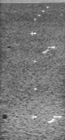
Fig. 13.4 Illustrating the assessment of vertical measurements using a typical tissue equivalent phantom
Horizontal measurements can be assessed by selecting two targets on a horizontal row of evenly spaced wires within the test phantom, as illustrated in Figure 13.5. Again, the measured distance can be compared with the known actual distance and expressed as a percentage error using the simple equation below:

Vertical and horizontal caliper measurements are affected by different factors. Vertical accuracy is determined by factors such as the speed of sound within the phantom whereas horizontal measurements are affected by other geometrical factors. Generally vertical (axial) measurements are more accurate than lateral measurements. Errors in either measurement of more than 2% are considered as unacceptable.
Greater accuracy is achieved by measuring distances between two wires which are positioned furthest apart rather than two which are only a couple of centimeters apart.
Circumference and area measurements are more difficult to assess and are usually conducted during routine QA testing which is normally performed by a medical physicist rather than the end user. Errors of more than 5% should be investigated.
2 Testing Image Resolution
Image resolution, referred to as spatial resolution, is defined as the ability of an ultrasound system to distinguish two closely spaced targets as separate objects (see Chapter 7 on Resolution). If a system has poor resolution capabilities, small structures lying close to each other will appear as one object, causing incorrect interpretation of the ultrasound image. Spatial resolution can be divided into two main components in the scan plane, namely axial and lateral resolution.
Testing axial and lateral resolution
Axial resolution is the ability of an ultrasound system to distinguish two closely spaced targets as separate images along the axis of the ultrasound beam. Axial resolution depends on the transducer’s operating frequency, damping characteristics, and spatial pulse length. Generally, the higher the frequency, the better the system’s axial resolution. Axial resolution is generally superior to lateral resolution.
Lateral resolution is the ability of an ultrasound system to distinguish two closely spaced targets as separate images which lie perpendicular or side by side to the ultrasound beam at the same depth from the transducer. Lateral resolution depends on the beam width, focusing characteristics of the transducer, number of displayed scan lines, and the system’s sensitivity and gain settings. The best lateral resolution is achieved at the focal point where the ultrasound beam is narrowest.
There are two ways of testing axial and lateral resolution:
These tests are normally performed by a medical physicist rather than the end user.
a) Object separation method
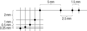
Most test phantoms contain a set of targets at different depths designed for the assessment of axial and lateral resolution which consist of a set of wires separated by decreasing vertical and horizontal spacing. An example is illustrated in Figure 13.6. The spacing of vertical wires to assess axial resolution decreases from a maximum separation distance of 2 mm to a minimum separation of 0.25 mm. In contrast, the spacing of horizontal target wires to assess lateral resolution is larger, ranging from a maximum separation of 5 mm to a minimum separation distance of 1.5 mm. This takes into account that lateral resolution is generally poorer than axial resolution in most imaging systems.
The system’s axial and lateral resolution are determined by identifying the set of two resolvable wires with the smallest separation. Figure 13.7 shows an image of a test phantom with such an arrangement of wires. It can be seen that the ultrasound system is able to resolve all targets along the vertical axis (axial plane) but is unable to resolve targets separated by a distance less than 2.5 mm across the image (lateral plane).

The main disadvantage with this technique is that the measurement values are limited to the spacing of targets within the test phantom and it is sometimes difficult to decide whether or not a pair of targets is resolved.
b) Single wire method
Using this method, any set of target wires can be chosen. Typically, the vertical set of target wires used to assess vertical distance are ideally suited for this (see Fig. 13.4).
The axial and lateral resolution is measured indirectly by measuring the length and width of individual wire targets at different depths corresponding to the transducer’s near, mid, and far field range. Figures 13.8 and 13.9 illustrate this method for measuring image resolution using a single wire target.
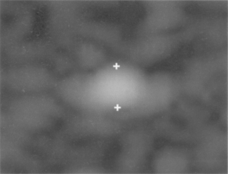
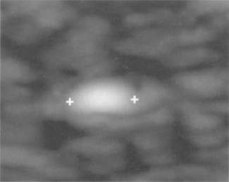
Using this single wire method, the image of the target is magnified using the machine’s zoom control facility to ensure that the errors when taking these small measurements are minimized. The main disadvantage of this technique is that it is sometimes difficult to identify and determine the edges of these blurred target wires.
3 Testing Depth of Penetration (Sensitivity)
Also known as sensitivity, this is the ability of the ultrasound system to detect and display low-amplitude echoes and refers to the depth at which the deepest echo signal within an image can be detected and clearly displayed by the ultrasound system.
Clinically, echoes received from small structures deep within the tissue are very weak due to the attenuation of the propagating ultrasound beam. The ability of an ultrasound system to detect, display, and differentiate these weak echoes from background noise is extremely important in the interpretation of the ultrasound image.
The point in the image where this is reached is known as the maximum penetration depth. The penetration depth is affected by a number of factors which include:
Measurement of penetration depth is useful and should be consistent over time. A loss in penetration depth, which can lead to a decrease in performance, can indicate a fault in one of the above factors.
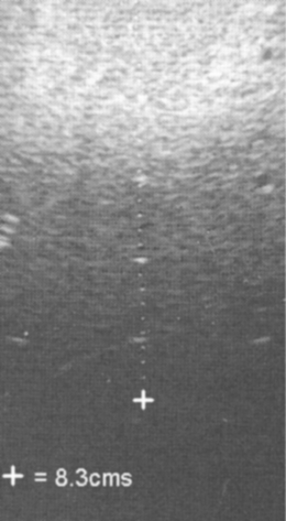
For meaningful and comparative assessments, this test is performed using exactly the same settings for a given transducer. These are normally performed using a test phantom with the machine operating at maximum output power and using a deep focal zone setting to obtain a measurement of the maximum penetration depth. Figure 13.10 shows a typical image using the recommended set-up to test the penetration depth. The maximum depth at which scattering echoes can be detected and differentiated from background electronic noise is determined and measured using the electronic calipers.
4 Assessing Dynamic Range
Dynamic range refers to the way that the gray scale information is compressed into a usable range for display on the monitor and is the ratio of the largest signal to the smallest. This ratio is usually expressed on a decibel scale (dB). Clinically, gray scale processing and displayed dynamic range allow echoes of varying degrees of amplitude to be displayed in the same image. A broader or wider dynamic range yields more shades of gray, while a smaller or narrower dynamic range results in a more black and white or more contrasted appearance of the image.
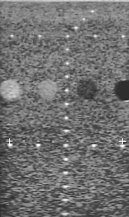
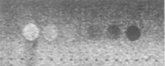
The gray scale processing and therefore dynamic range of an ultrasound system can be assessed by using a suitable test phantom which typically consists of a group of targets which have varying contrasts relative to the background. An example of a typical test phantom is shown in Figure 13.11, and consists of a number of cylinders (which are imaged in cross-section) filled with a material of different scattering strengths to create areas of known and varying gray levels and echogenicity. Figure 13.12 shows an image using such a phantom to assess a system’s dynamic range. This is estimated from the difference between the brightest and darkest regions which can be imaged simultaneously.

ELECTRICAL AND MECHANICAL SAFETY
Equipment-related physical checks should also be included in any ultrasound QA testing program and include regular visual inspection of:
LIMITATIONS OF ULTRASOUND QA TESTING
A substantial effort has been made to determine the most appropriate and clinically relevant tests, with recommendations by many professional bodies who have published general guidelines describing standard methods for measuring the performance of ultrasound systems. These outline the most appropriate imaging tests, i.e. parameters that should be tested, the frequency of this testing, and the most appropriate phantoms to use. However, there are many machine controls and variables that must be considered which, on modern ultrasound systems, are difficult to individually control without affecting each other. This makes a clinically meaningful assessment regarding the performance of the ultrasound system using test phantoms subjective and difficult to quantify. To obtain optimum and reproducible results, it is important to take a rational and consistent approach to the ultrasound system’s settings.
A straightforward approach adopted by the end user should include some basic tests such as checking caliper accuracy and measuring the depth of penetration, for example. These are extremely useful to monitor the performance of an ultrasound system.
Recent developments in technology leading to the use of higher frequency transducers with improved image resolution, for example, have improved the performance of ultrasound equipment to such an extent that many machines are now able to resolve targets on current phantoms easily. There is therefore a growing need for a new generation of test phantoms in order to measure adequately the capabilities of new equipment.
Further developments in ultrasound performance testing and phantoms are necessary and should lead to a standard practice of QA in all ultrasound departments in the future. As end users, we need to ensure that the equipment we use is adequate and appropriate to ensure high-quality diagnostic ultrasound imaging is achieved and maintained.
SUMMARY
American College of Radiology. ACR Technical standard for diagnostic medical physics performance monitoring of real time B-mode ultrasound equipment. Virginia: ACR, Reston, 1999.
Goodsitt MM, Carson PL, Witt S, et al, editors. Report of AAPM Ultrasound Task Group No 1: Real-time B-mode ultrasound quality control test procedures, 25. Medical Physics. 1998:1385-1406. 8.
Madsen E, editor. Quality assurance manual for gray scale ultrasound scanners (Stage 2). Maryland: AIUM, Laurel, 1995.
Medical Devices Agency. Evaluation Report MDA/98/52. London: HMSO, 1999.