Processing X-Ray Film
The recording medium (image receptor) most frequently used in dental radiography is radiographic film. Making excellent film radiographs will improve patient diagnoses and overall care. Making excellent radiographs requires using the proper film exposure times and optimizing film processing. This chapter describes these processes starting with the formation of the latent image, followed by conversion of the latent image into a visible image (film processing), and closing with how to establish the proper exposure time.
Formation of the Latent Image
When a beam of photons exits an object and exposes an x-ray film, it chemically changes the photosensitive silver halide crystals in the film emulsion. These chemically altered silver bromide crystals constitute the latent (invisible) image on the film. Before exposure, film emulsion consists of photosensitive crystals containing primarily silver bromide suspended in a vehicle and layered on a thin sheet of transparent plastic base. Some crystals also contain small amounts of silver iodide. These silver halide crystals also contain a few free silver ions (interstitial silver ions) in the spaces between the crystalline lattice atoms (Fig. 6-1, A). The crystals are chemically sensitized by the addition of trace amounts of sulfur compounds, which bind to the surface of the crystals. The sulfur compounds play a crucial role in image formation. Along with physical irregularities in the crystal produced by iodide ions, sulfur compounds create sensitivity sites, the sites in the crystals that are sensitive to radiation. Each crystal has many sensitivity sites, which begin the process of image formation by trapping the electrons generated when the emulsion is irradiated. Exposure to radiation chemically alters the photosensitive silver halide crystals to produce the latent image. Processing the exposed film in developer and fixer converts the latent image into the visible radiographic image.
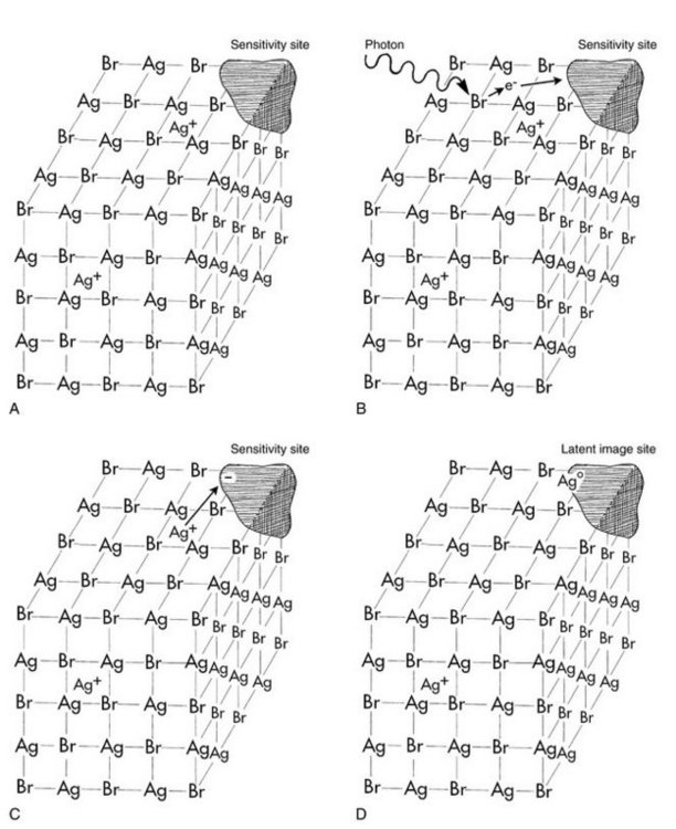
FIG. 6-1 A, A silver bromide crystal in the emulsion of an x-ray film contains mostly silver and bromide ions in a crystal lattice. There are also free interstitial silver ions and areas of trace chemicals that form sensitivity sites. B, Exposure of the crystal to photons in an x-ray beam results in the release of electrons, usually by interaction of the photon with a bromide ion. Bromide ions are converted to bromine atoms, and the recoil electrons have sufficient kinetic energy to move about in the crystal. When electrons reach a sensitivity site, they impart a negative charge to this region. C, Free interstitial silver ions (with a positive charge) are attracted to the negatively charged sensitivity site. D, When the silver ions reach the sensitivity site, they acquire an electron and become neutral silver atoms. These silver atoms now constitute a latent image site. The collection of latent image sites over the entire film constitutes the latent image. Developer causes the neutral silver atoms at the latent image sites to initiate the conversion of silver ions in the crystal into one large grain of metallic silver.
When the silver halide crystals are irradiated, x-ray photons interact primarily with the bromide ions by Compton and photoelectric interactions (Fig. 6-1, B). These interactions result in the removal of an electron from the bromide ions. By the loss of an electron, a bromide ion is converted into a neutral bromine atom. The free electrons move through the crystal until they reach a sensitivity site, where they become trapped and impart a negative charge to the site. The negatively charged sensitivity site then attracts positively charged free interstitial silver ions (Fig. 6-1, C). When a silver ion reaches the negatively charged sensitivity site, it is reduced and forms a neutral atom of metallic silver (Fig. 6-1, D). The sites containing these neutral silver atoms are now called latent image sites. This process occurs numerous times within a crystal. The overall distribution of latent image sites in a film after exposure constitutes the latent image.
Film processing converts the latent image into one that can be visualized (Fig. 6-2). The neutral silver atoms at each latent image site (Fig. 6-2, B) render the crystals sensitive to development and image formation. The larger the aggregate of neutral silver atoms, the more sensitive the crystal is to the effects of the developer. Most latent image sites that are capable of being developed in an optimally exposed film have at least four or five silver atoms. Developer converts silver bromide crystals with neutral silver atoms deposited at the latent image sites into black, solid silver metallic grains (Fig. 6-2, C). These solid silver grains block light from a viewbox. Fixer removes unexposed, undeveloped silver bromide crystals (those without latent image sites), leaving the film clear in unexposed areas (Fig. 6-2, D). Thus the radiographic image is composed of the light (radiopaque) areas, where few photons reached the film, and dark (radiolucent) areas of the film that were struck by many photons.
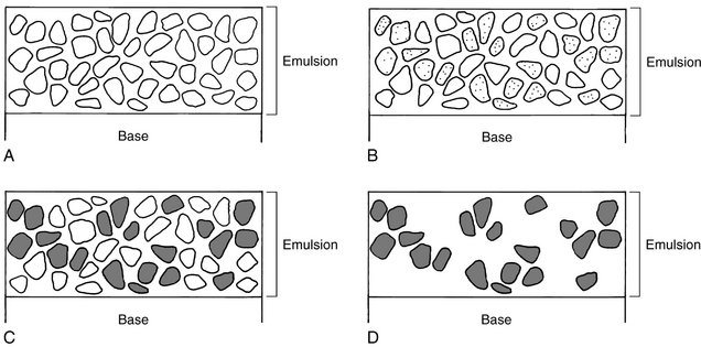
FIG. 6-2 Emulsion changes during film processing. A, Before exposure, many silver bromide crystals are present in the emulsion. B, After exposure, the exposed crystals containing neutral silver atoms at latent image sites constitute the latent image (shaded areas in the crystals). C, The developer converts the exposed crystals containing neutral silver atoms at the latent image sites into solid grains of metallic silver. D, The fixer dissolves the unexposed, undeveloped silver bromide crystals, leaving only the solid silver grains. (Courtesy C.L. Crabtree, DDS, Bureau of Radiological Health, Rockville, Md.)
Processing solutions
Film processing involves the following procedures:
This chapter first describes the function of developer and fixer. Procedures for each of these steps are described later.
DEVELOPING SOLUTION
The developer reduces all silver ions in the exposed crystals of silver halide (those with a latent image) to metallic silver grains (see Fig. 6-2). To produce a diagnostic image, this reduction process must be restricted to crystals containing latent image sites. To accomplish this, the reducing agents used as developers are catalyzed by the neutral silver atoms at the latent image sites (see Fig. 6-2, B). The silver atoms act as a bridge by which electrons from the reducing agents reach silver ions in the crystal and convert them to solid grains of metallic silver. Individual crystals are developed completely or not at all during the recommended developing times (see Fig. 6-2, C). Variations in density on the processed radiographs are the result of different ratios of developed (exposed) and undeveloped (unexposed) crystals. Areas with many exposed crystals are denser because of their higher concentration of black metallic silver grains after development. If the developer remains too long in contact with silver bromide halide crystals that do not contain a latent image, it slowly reduces these crystals also, thereby overdeveloping the image.
When an exposed film is developed, the developer initially has no visible effect (Fig. 6-3). After this initial phase, the density increases, very rapidly at first and then more slowly. Eventually all the exposed crystals develop (become reduced to black metallic silver), and the developing agent starts to reduce the unexposed crystals. The development of unexposed crystals results in chemical fog on the film. The interval between maximal density and fogging explains why a properly exposed film does not become overdeveloped although it may be in contact with the developer longer than the recommended interval. Thus dark films usually are the result of overexposure rather than overdevelopment.
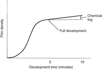
FIG. 6-3 Relationship between film density and development time. The density of film rises quickly initially and then levels off, increasing more slowly because of chemical fogging.
The developing solution contains four components, all dissolved in water: (1) developer, (2) activator, (3) preservative, and (4) restrainer.
Developer
The primary function of the developing solution is to convert the exposed silver halide crystals into metallic silver grains. This process begins at the latent image sites, where electrons from the developing agents are conducted into the silver halide crystal and reduce the constituent silver ions (approximately 1 billion to 10 billion) to solid grains of metallic silver. Two developing agents are used in dental radiology: a pyrazolidone-type compound, usually Phenidone (1-phenyl-3-pyrazolidone), and hydroquinone (paradihydroxy benzene). Phenidone serves as the first electron donor that converts silver ions to metallic silver at the latent image site. This electron transfer generates the oxidized form of Phenidone. Hydroquinone provides an electron to reduce the oxidized Phenidone back to its original active state so that it can continue to reduce silver halide grains to metallic silver. Unexposed crystals, those without latent images, are unaffected during the time required for reduction of the exposed crystals.
Activator
The developers are active only at alkaline pH values, usually around 10. This is achieved with the addition of alkali compounds (activators) such as sodium or potassium hydroxide. Buffers—usually sodium bicarbonate—are used to maintain this condition. The activators also cause the gelatin to swell so that the developing agents can diffuse more rapidly into the emulsion and reach the suspended silver bromide crystals.
Preservative
The developing solution contains an antioxidant or preservative, usually sodium sulfite. The preservative protects the developers from oxidation by atmospheric oxygen and thus extends their useful life. The preservative also combines with the brown oxidized developer to produce a colorless soluble compound. If not removed, oxidation products interfere with the developing reaction and stain the film.
Restrainer
Bromide, usually as potassium bromide, and benzotriazole are added to the developing solution to restrain development of unexposed silver halide crystals. Although bromide and benzotriazole depress the reduction of both exposed and unexposed crystals, they are much more effective in depressing the reduction of unexposed crystals. Consequently, the restrainers act as antifog agents and increase contrast.
DEVELOPER REPLENISHER
In the normal course of film processing, Phenidone and hydroquinone are consumed, and bromide ions and other byproducts are released into solution. Developer also becomes inactivated by exposure to oxygen. These actions produce a “seasoned” solution, and the film speed and contrast stabilize. The developing solution of both manual and automatic developers should be replenished with fresh solution each morning to prolong the life of the seasoned developer. The recommended amount to be added daily is 8 ounces of fresh developer (replenisher) per gallon of developing solution. This assumes the development of an average of 30 periapical or 5 panoramic films per day. Some of the used solution may need to be removed to make room for the replenisher.
RINSING
After development the film emulsion swells and becomes saturated with developer. At this point the films are rinsed in water for 30 seconds with continuous, gentle agitation before they are placed in the fixer. Rinsing dilutes the developer, slowing the development process. It also removes the alkali activator, preventing neutralization of the acid fixer. This rinsing process is typical for manual processing but is not used with automatic processing.
FIXING SOLUTION
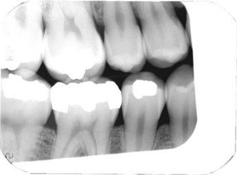
The primary function of fixing solution is to dissolve and remove the undeveloped silver halide crystals from the emulsion (see Fig. 6-2, D). The presence of unexposed crystals causes film to be opaque. If these crystals are not removed, the image on the resultant radiograph is dark and nondiagnostic. Figure 6-4 is a photomicrograph of film emulsion showing the solid silver grains after fixer has removed the unexposed silver bromide crystals. (Compare it with Fig. 45-2, A, which shows the unprocessed emulsion.) A second function of fixing solution is to harden and shrink the film emulsion. As with developer, fixer should be replenished daily at the rate of 8 ounces per gallon.
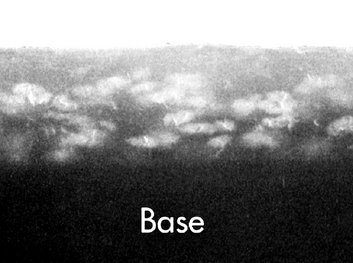
FIG. 6-4 Scanning electron micrograph of a processed emulsion of Kodak Ultra-Speed dental x-ray film (5000×). Note the white-appearing solid silver grains above the base. (Courtesy Carestream Health, Inc., exclusive manufacturer of Kodak dental systems.)
Fixing solution also contains four components, all dissolved in water: (1) clearing agent, (2) acidifier, (3) preservative, and (4) hardener.
Clearing Agent
After development the film emulsion must be cleared by dissolving and removing the unexposed silver halide. An aqueous solution of ammonium thiosulfate (“hypo”) dissolves the silver halide grains. It forms stable, water-soluble complexes with silver ions, which then diffuse from the emulsion. The clearing agent does not have a rapid effect on the metallic silver grains in the film emulsion, but excessive fixation results in a gradual loss of film density because the grains of silver slowly dissolve in the acetic acid of the fixing solution.
Acidifier
The fixing solution contains an acetic acid buffer system (pH 4 to 4.5) to keep the fixer pH constant. The acidic pH is required to promote good diffusion of thiosulfate into the emulsion and of silver thiosulfate complex out of the emulsion. The acid-fixing solution also inactivates any carryover developing agents in the film emulsion, blocking continued development of any unexposed crystals while the film is in the fixing tank.
Preservative
Ammonium sulfite is the preservative in the fixing solution, as it is in the developer. It prevents oxidation of the thiosulfate clearing agent, which is unstable in the acid environment of the fixing solution. It also binds with any colored oxidized developer carried over into the fixing solution and effectively removes it from the solution, which prevents oxidized developer from staining the film.
Hardener
The hardening agent most often used is aluminum sulfate. Aluminum complexes with the gelatin during fixing and prevents damage to the gelatin during subsequent handling. The hardeners also reduce swelling of the emulsion during the final wash. This lessens mechanical damage to the emulsion and limits water absorption, thus shortening drying time.
WASHING
After fixing, the processed film is washed in a sufficient flow of water for an adequate time to ensure removal of all thiosulfate ions and silver thiosulfate complexes. Washing efficiency declines rapidly when the water temperature falls below 60° F. Any silver compound or thiosulfate that remains because of improper washing discolors and causes stains, which are most apparent in the radiopaque (light) areas. This discoloration results from the thiosulfate reacting with silver to form brown silver sulfide, which can obscure diagnostic information.
Darkroom Equipment
The darkroom should be convenient to the x-ray machines and dental operatories and should be at least 4 × 5 feet (1.2 × 1.5 m) (Fig. 6-5). It must be well operated to ensure excellent radiographs.
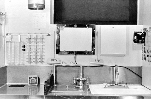
FIG. 6-5 Darkroom work area. Left, Film mounting area, timer, film racks, and safelight above. Middle, Developing and fixing tanks below the viewbox and stirring paddles. Right, Sink and drying racks with fan. (Courtesy C.L. Crabtree, DDS, Bureau of Radiological Health, Rockville, Md.)
LIGHTPROOF
One of the most important requirements is that the darkroom be lightproof. If it is not, stray light will cause film fogging and loss of contrast. To make the darkroom lightproof, a light-tight door or doorless maze (if space permits) is used. The door should have a lock to prevent accidental opening, which might allow an unexpected flood of light that can ruin opened films.
The darkroom must also be well ventilated for the comfort of those working in the area and to exhaust the heat from the dryer and moisture from the drying films. Also, a comfortable room temperature helps maintain optimal conditions for developing, fixing, and washing solutions. If supplies (including unexposed x-ray film) are to be stored in the darkroom, ventilation is doubly important because temperatures of 90° F or higher can cause a generalized increase in density (film fog) on the film.
SAFELIGHTING
The processing room should have both white illumination and safelighting. Safelighting is low-intensity illumination of relatively long wavelength (red) that does not rapidly affect open film but permits one to see well enough to work in the area (Fig. 6-6). To minimize the fogging effect of prolonged exposure, the safelight should have a 15-watt bulb and should be mounted at least 4 feet above the surface where opened films are handled. A new type of safelight uses a cluster of 20 red-emitting diodes, thus not needing a filter.
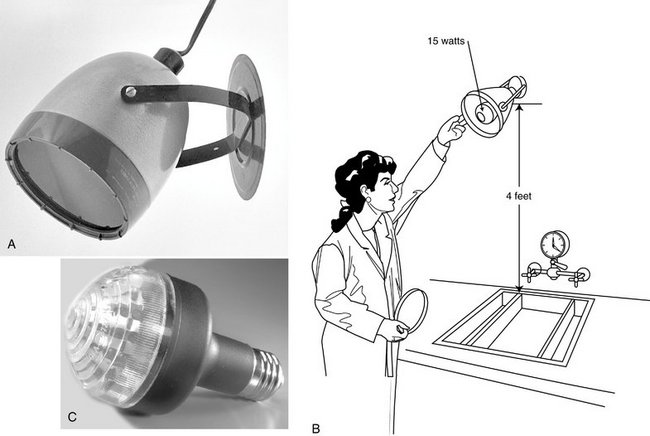
FIG. 6-6 A, A safelight may be mounted on the wall or ceiling in the darkroom and should be at least 4 feet from the work surface. B, The safelight uses a GBX-2 filter and 15-watt bulb. C, Bulb with cluster of 20 red-emitting diodes does not need a filter. (C, Courtesy Carestream Health, Inc., exclusive manufacturer of Kodak dental systems.)
X-ray films are very sensitive to the blue-green region of the spectrum and are less sensitive to yellow and red wavelengths. Accordingly, the red GBX-2 filter is recommended as a safelight in darkrooms where either intraoral or extraoral films are handled because this filter transmits light only at the red end of the spectrum (Fig. 6-7). Film handling under a safelight should be limited to about 5 minutes because film emulsion shows some sensitivity to light from a safelight with prolonged exposure. The older ML-2 filters (yellow light) are not appropriate for fast intraoral dental film or extraoral panoramic or cephalometric film.
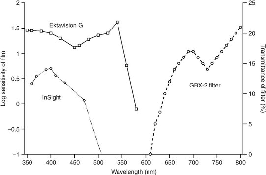
FIG. 6-7 Spectral sensitivities of Ektavision G film (heavy line with squares) and InSight film (dotted line with diamonds) shown with the transmission characteristics of a GBX-2 filter (broken line with circles). Note that the films are more sensitive in the blue-green portion of the spectrum (shorter than 600 nm); the GBX-2 filter transmits primarily red light (longer than 600 nm).
MANUAL PROCESSING TANKS
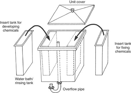
All dental offices should have the capability to develop film by tank processing, if only as a backup for an automatic processor or digital imaging system. The tank must have hot and cold running water and a means of maintaining the temperature between 60° and 75° F. A practical size for a dental office is a master tank about 20 × 25 cm (8 × 10 inches) that can serve as a water jacket for two removable inserts that fit inside (Fig. 6-8). The insert tanks usually hold 3.8 L (1 gallon) of developer or fixer and are placed within the outer, larger master tank. The outer tank holds the running water for maintaining the temperature of the developer and fixer in the insert tanks and for washing films. The developer customarily is placed in the insert tank on the left side of the master tank and the fixer in the insert tank on the right. All three tanks should be made of stainless steel, which does not react with the processing solutions and is easy to clean. The master tank should have a cover to reduce oxidation of the processing solutions, protect the developing film from accidental exposure to light, and minimize evaporation of the processing solutions.
THERMOMETER
The temperature of the developing, fixing, and washing solutions should be closely controlled. A thermometer can be left in the water circulating through the master tank to monitor the temperature and ensure that the water temperature regulator is working properly. The most desirable thermometers clip onto the side of the tank. Thermometers may contain alcohol or metal, but they should not contain mercury because they could break and contaminate the processor or solutions.
TIMER
The x-ray film must be exposed to the processing chemicals for specific intervals. An interval timer is indispensable for controlling development and fixation times.
DRYING RACKS
Two or three drying racks can be mounted on a convenient wall for film hangers. Drip trays are placed underneath the racks to catch water that may run off the wet films. An electric fan can be used to circulate the air and speed the drying of films, but it should not be pointed directly at the films. Also, cabinet dryers are available that circulate warm air around the film and accelerate drying. Excessive heat must be avoided because it may damage the emulsion. If dryers are installed in the darkroom, they should be ventilated outside the darkroom to preclude high humidity and heat, which are detrimental to any unexposed film stored in the room.
Manual Processing Procedures
Manual processing of film requires the following eight steps:
1. Replenish solutions. The first step in manual tank processing is to replenish the developer and fixer. Add fresh developer (replenisher) and fixer (8 ounces per gallon) to maintain the proper strength of each solution. Check the solution levels to ensure that the developer and fixer cover the films on the top clips of the film hangers.
2. Stir solutions. Next, stir the developer and fixing solution to mix the chemicals and equalize the temperature throughout the tanks. To prevent cross-contamination, use a separate paddle for each solution. It is best to label one paddle for the developer and the other for the fixer. Because proper developing time varies with the temperature of the solution, check the temperature of the developer after stirring.
3. Mount films on hangers. Using only safelight illumination in the darkroom, remove the exposed film from its lightproof packet or cassette. Hold the films only by their edges to avoid damage to the film surface. Clip the bare film onto a film hanger, one film to a clip (Fig. 6-9). To avoid any possible confusion later, label the film racks with the patient’s name and the exposure date.
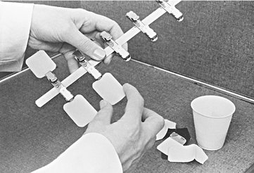
FIG. 6-9 Films are mounted securely on film clips. Film is always held by its edges to avoid fingerprints on the image. (Courtesy C.L. Crabtree, DDS, Bureau of Radiological Health, Rockville, Md.)
4. Set timer. Check the temperature of the developer and set the interval timer to the time indicated by the manufacturer for the solution temperature. For intraoral film processing in conventional solutions, use the following development times:
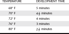
Processing films at either higher or lower temperatures and for longer or shorter times than recommended by the manufacturer reduces the contrast of the processed film. Also, processing too long or at temperatures higher than those recommended can result in film fog, which may diminish film contrast and diagnostic information.
5. Develop. Start the timer mechanism and immerse the hanger and films immediately in the developer. Agitate the hanger mildly for 5 seconds to sweep air bubbles off the film. Leave the films in the developer for the predetermined time without further agitation. When removing the films, drain the excess developer into the wash bath.
6. Rinse. After development, remove the film hanger from the developer and place in the running water bath for 30 seconds. Agitate the films continuously in the rinse water to remove excess developer, thus slowing development and minimizing contamination of the fixer.
7. Fix. Place the hanger and film in the fixer solution for 2 to 4 minutes and agitate for 5 of every 30 seconds. This eliminates bubbles and brings fresh fixer into contact with the emulsion. Excess fixation (several hours) removes some of the metallic silver grains, diminishing the density of the film. When the films are removed, drain the excess fixer into the wash bath.
8. Wash and dry. After fixation of the films is complete, place the hanger in running water for at least 10 minutes to remove residual processing solutions. After the films have been washed, remove surface moisture by gently shaking excess water from the films and hanger. Dry the films in circulating, moderately warm air. If the films dry rapidly with small drops of water clinging to their surface, the areas under the drops dry more slowly than the surrounding areas. This uneven drying causes distortion of the gelatin, leaving a drying artifact in some cases. The result is spots that frequently are visible and detract from the usefulness of the finished radiograph. After drying, the films are ready to mount.
Rapid-processing Chemicals
In recent years a number of manufacturers have produced rapid-processing solutions. These solutions typically develop films in 15 seconds and fix them in 15 seconds at room temperature. They have the same general formulation as conventional processing solutions but often contain a higher concentration of hydroquinone. They also have a more alkaline pH than conventional solutions, which causes the emulsion to swell more, thus providing greater access to developer. These solutions are especially advantageous in endodontics and in emergency situations, when short processing time is essential. Although the resultant images may be satisfactory, they often do not achieve the same degree of contrast as films processed conventionally, and they may discolor over time if not fully washed. After viewing, rapidly processed films are placed in conventional fixing solution for 4 minutes and washed for 10 minutes. This improves the contrast and helps keep them stable in storage. Conventional solutions are preferred for most routine use.
Changing Solutions
All processing solutions deteriorate as a result of continued use and exposure to air. Although regular replenishment of the developer and fixer prolongs their useful life, the buildup of reaction products eventually causes these solutions to cease functioning properly. Exhaustion of the developer results from oxidation of the developing agents, depletion of the hydroquinone, and buildup of bromide. Use of exhausted developer results in films that show reduced density and contrast. When the fixer becomes exhausted, silver thiosulfate complexes form and halide ions build up. The increased concentration of silver thiosulfate complexes slows the rate of diffusion of these complexes from the emulsion. The halide ions slow the rate of clearing of unexposed silver halide crystals. These changes result in films with incomplete clearing that turn brown with age. With regular replenishment, solutions may last 3 or 4 weeks before they must be changed. When the developer and fixer are replaced, the solutions must be prepared according to the directions on the containers.
A simple procedure can help determine when solutions should be changed. A double film packet instead of a single film packet is exposed on one projection for the first patient radiographed after new solutions have been prepared. One film is placed in the patient’s chart, and the other is mounted on a corner of a viewbox in the darkroom. As successive films are processed, they are compared with this reference film. Loss of image contrast and density become evident as the solutions deteriorate, indicating when the time has come to change them. The fixer is changed when the developer is changed.
Automatic Film Processing
Equipment that automates all processing steps is available (Fig. 6-10). Although automatic processing has a number of advantages, the most important is the time saved. Depending on the equipment and the temperature of operation, an automatic processor requires only 4 to 6 minutes to develop, fix, wash, and dry a film. Many dental automatic processors have a light-shielded (daylight loading) compartment in which the operator can unwrap films and feed them into the machine without working in a darkroom. This is desirable because the individual doing the developing does not have to work in the dark. However, special care must be taken to maintain infection control when using these daylight-loading compartments (see Chapter 8).
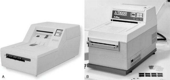
FIG. 6-10 Automatic film processors. A, Dent-X 810 AR film processor. B, A/T 2000XR. (A, Courtesy AFP Imaging/Dent-X, Elmsford, N.Y.; B, courtesy Air Techniques, Inc., Hicksville, N.Y.)
When extraoral films are processed, the light-shielded compartment is removed to provide room for feeding the larger film into the processor. Another attractive feature of the automatic system is that the density and contrast of the radiographs tend to be consistent. However, because of the higher temperature of the developer and the artifacts caused by rollers, the quality of films processed automatically often is not as high as that of those carefully developed manually. With automatically processed films, more grain usually is evident in the final image.
Whether automatic processing equipment is appropriate for a specific practice depends on the dentist and the nature and volume of the practice. The equipment is expensive and must be cleaned frequently. Also, the automated equipment may break down, and conventional darkroom equipment may still be needed as a backup system.
MECHANISM
Automatic processors have an in-line arrangement. Typically, this consists of a transport mechanism that picks up the unwrapped film and passes it through the developing, fixing, washing, and drying sections (Fig. 6-11). The transport system most often used is a series of rollers driven by a constant-speed motor that operates through gears, belts, or chains. The rollers often consist of independent assemblies of multiple rollers in a rack, with one rack for each step in the operation. Although these assemblies are designed and positioned so that the film crosses over from one roller to the next, the operator may remove them independently for soaking, cleaning, and repairing.
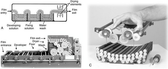
FIG. 6-11 A, Automatic film processors typically consist of a roller assembly that transports the film through developing, fixing, washing, and drying stations. B, Assembly of film transport mechanism. C, Complete internal transport system. (B and C, Courtesy AFP Imaging/Dent-X, Elmsford, N.Y.)
The primary function of the rollers is to move the film through the developing solutions, but they also serve at least three other purposes. First, their motion helps keep the solutions agitated, which contributes to the uniformity of processing. Second, in the developer, fixer, and water tanks the rollers press on the film emulsion, forcing some solution out of the emulsion. The emulsions rapidly fill again with solution, thus promoting solution exchange. Finally, the top rollers at the crossover point between the developer and fixer tanks remove developing solution, minimizing carryover of developer into the fixer tank. This feature helps maintain the uniformity of processing chemicals.
The chemical compositions of the developer and fixer are modified to operate at higher temperatures than those used for manual processing and to meet the more rapid development, fixing, washing, and drying requirements of automatic processing. The fixer has an additional hardener that helps the emulsion withstand the rigors of the transport system.
OPERATION
Successful operation of an automatic processor requires standardized procedures and regular maintenance. The processor and surrounding area should always be kept clean so that no chemicals contaminate hands or films. Each morning the solution level and temperature should be checked before films are processed. Hands should be dry when handling film, and films should be touched only by their edges. The better processors have automatic replenishment systems. Once a week a maintenance routine should be followed, including cleaning the rollers and other working parts. It is also often useful to run a large film through the processor to clean the rollers.
REPLENISHMENT
It is important to maintain the constituents of the developer and fixer carefully to preserve the optimal sensitometric and physical properties of the film emulsion within the narrow limits imposed by the speed and temperature of automatic processing. As the activity of the developing and fixing solutions lessens, its effect on the film diminishes. To compensate for this loss of activity, some automatic processors include an automatic replenishment system that adds fresh developer to the developer tank and fresh fixer to the fixer tank. As with manual processing, 8 ounces of fresh developer and fixer should be added per gallon of solution per day. This assumes an average workload of 30 intraoral or 5 extraoral films per day. Insufficient replenishment of the developer results in a loss of image contrast. Exhaustion of the fixing solution causes poor clearing of the film, insufficient hardening of the emulsion, and unreliable transport from the fixer assembly through the drying operation.
Establishing Correct Exposure Times
When radiographs are first made with a new x-ray machine, it is important to examine the exposure guidelines that come with the machine. Typically such guidelines provide a table listing the various anatomic regions: incisors, premolars, or molars; patient size: adult or child; and the length of the aiming cylinder. For each of these combinations there will be a suggested exposure time. It is also important to start out using fresh processing chemicals and optimal processing conditions as previously described. After the first images are made on patients, it may be necessary to adjust exposure time. If optimal film processing techniques are being followed and the images are consistently dark, then exposure times should be decreased until optimal images are obtained. If images are consistently light, then exposure times should be increased. Once the optimal times have been determined, then these values should be posted by the control panel.
Management of Radiographic Wastes
To prevent environmental damage, many communities and states have passed laws governing the disposal of wastes. Such laws often derive from the federal Resource Conservation and Recovery Act of 1976. Although dental radiographic waste constitutes only a small potential hazard, it should be discarded properly. The primary ingredient of concern in processing solutions is the dissolved silver found in used fixer. Another material of concern is the lead foil found in film packets.
Several means are available for properly disposing of the silver and lead. Silver may be recovered from the fixer by use of either the metallic replacement or electroplating methods. Metallic replacement uses cartridges through which waste solutions are poured. In this process, iron goes into the solution and the silver precipitates as sludge. In the electroplating method, the waste solutions come in contact with two electrodes through which a current passes. The cathode captures the silver. In either case, the scrap silver can be sold to silver refiners and buyers.
The lead foil is separated from the packet and collected until enough has been accumulated to sell to a scrap metal dealer. Dental offices also should consider using companies licensed to pick up waste materials. The names of such companies can be found in the telephone directory or obtained from the state hazardous waste management agency.
Common Causes of Faulty Radiographs
Although film processing can produce radiographs of excellent quality, inattention to detail may lead to many problems and images that are diagnostically suboptimal. Poor radiographs contribute to a loss of diagnostic information and loss of professional and patient time. Box 6-1 presents a list of common causes of faulty radiographs. The steps necessary for correction are self-evident.
BOX 6-1 Common Problems in Film Exposure and Development
Light Radiographs (Fig. 6-12)
Film-source distance too great
Film packet reversed in mouth (Fig. 6-13)
Insufficient Contrast (Fig. 6-15)
Film Fog (Fig. 6-16)
Improper safelighting (improper filter; excessive bulb wattage; inadequate distance between safelight and work surface; prolonged exposure to safelight)
Light leaks (cracked safelight filter; light from doors, vents, or other sources)
Deteriorated film (stored at high temperature; stored at high humidity; exposed to radiation; outdated)
Dark Spots or Lines (Fig. 6-17)
Light Spots (Fig. 6-18)
Blurring (Fig. 6-19)
Partial Images (Fig. 6-20)
Mounting Radiographs
Radiographs must be preserved and maintained in the most satisfactory and useful condition. Periapical, interproximal, and occlusal films are best handled and stored in a film mount (Fig. 6-21). The operator can handle them with greater ease, and there is less chance of damaging the emulsion. Mounts are made of plastic or cardboard and may have a clear plastic window that covers and protects the film. However, the window may have scratches or imperfections that interfere with radiographic interpretation. The operator can arrange several films from the same individual in a film mount in the proper anatomic relationship. This facilitates correlation of the clinical and radiographic examinations. Opaque mounts are best because they prevent stray light from the viewbox from reaching the viewer’s eyes.
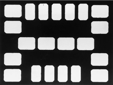
FIG. 6-21 Film mount for holding nine narrow anterior periapical views, eight posterior periapical views, and four bitewing views.
The preferred method of positioning periapical and occlusal films in the film mount is to arrange them so that the images of the teeth are in the anatomic position and have the same relationship to the viewer as when the viewer faces the patient. The radiographs of the teeth in the right quadrants should be placed in the left side of the mount and those of the left quadrants in the right side. This system, advocated by the American Dental Association, allows the examiner’s gaze to shift from radiograph to tooth without crossing the midline. The alternative arrangement, with the images of the right quadrants on the right side of the mount and those of the left quadrant on the left, is not recommended.
Duplicating Radiographs
Occasionally radiographs must be duplicated; this is best accomplished with duplicating film. The film to be duplicated is placed against the emulsion side of the duplicating film, and the two films are held in position by a glass-topped cassette or photographic printing frame. The films are exposed to light, which passes through the clear areas of the original radiograph and exposes the duplicating film. The duplicating film is then processed in conventional x-ray processing solutions.
Unlike conventional x-ray film, duplicating film gives a positive image. Thus areas exposed to light come out clear, as on the original radiograph. Duplication typically results in images with less resolution and more contrast than the original radiograph. The best images are obtained when a circular, ultraviolet light source is used. In contrast to the usual negative film, images on duplicating film that are too dark or too light are underexposed or overexposed, respectively.
Eikenberg, S, Vandre, R. Comparison of digital dental X-ray systems with self-developing film and manual processing for endodontic file length determination. J Endod. 2000;26:65–67.
Farman, TT, Farman, AG. Evaluation of a new F speed dental X-ray film: the effect of processing solutions and a comparison with D and E speed films. Dentomaxillofac Radiol. 2000;29:41–45.
Fitterman, AS, Brayer, FC, Cumbo, PE, Processing chemistry for medical imaging. Technical and Scientific Monograph No. 5, N-327. Rochester, NY: Eastman Kodak; 1995.
Kodak. Exposure and processing for dental film processing. N-413 http://www.kodakdental.com/en/film/support. Accessed May 7, 2008
Ludlow, JB, Platin, E, Delano, EO, et al. The efficacy of caries detection using three intraoral films under different processing conditions. J Am Dent Assoc. 1997;128:1401–1408.
Mees, DEK, James, TH. The theory of the photographic process. New York: Macmillan; 1977.
Syriopoulos, K, Velders, XL, Sanderink, GC, et al. Sensitometric evaluation of four dental x-ray films using five processing solutions. Dentomaxillofac Radiol. 1999;28:73–79.