Cone-Beam Computed Tomography
Cone-beam computed tomography (CBCT) is a recent technology initially developed for angiography in 1982 and subsequently applied to maxillofacial imaging. It uses a divergent or “cone”-shaped source of ionizing radiation and a two-dimensional area detector fixed on a rotating gantry to acquire multiple sequential projection images in one complete scan around the area of interest (Fig. 14-1). It is only since the late 1990s that it has become possible to produce clinical systems that are both inexpensive and small enough to be used in the dental office. Four technologic factors have converged to make this possible: (1) the development of compact high-quality flat-panel detector arrays, (2) reductions in the cost of computers capable of image reconstruction, (3) development of inexpensive x-ray tubes capable of continuous exposure and, (4) limited-volume scanning (e.g., head and neck), eliminating the need for subsecond gantry rotation speeds.
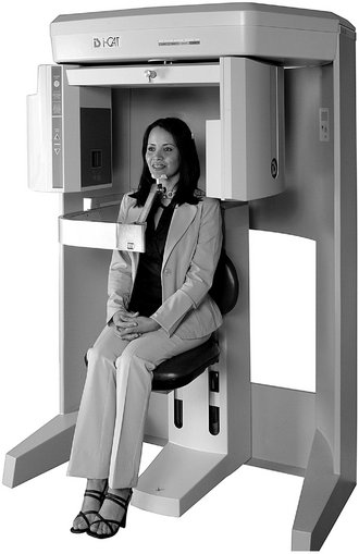
FIG. 14-1 Example of CBCT unit.
Imaging may be performed with the patient seated, supine, or standing. The patient’s head is positioned and stabilized between the x-ray generator and detector by a head-holding apparatus. The detector may be a flat panel (this example) or image intensifier. During exposure the generator and detector rotate fully or partially around the patient’s head. Scan time is as fast as 5 seconds. Most CBCT units have a small “footprint” enabling in-office placement. (Courtesy Imaging Sciences International, Hatfield, Pa.)
This technology has been given several names including dental volumetric tomography, cone-beam volumetric tomography, dental computed tomography, and cone-beam imaging. The most frequently applied and preferred term is cone-beam computed tomography because it is a digital analog of film tomography in a more exact way than is traditional computed tomography (CT), the x-ray is either conical or pyramidal, and the technology is not limited to dentistry. The principal feature of CBCT is that multiple planar projections are acquired by rotational scan to produce a volumetric dataset from which interrelational images can be generated.
Principles of Cone-beam Computed Tomography
All CT scanners consist of an x-ray source and detector mounted on a rotating gantry. During rotation of the gantry, the receptor detects x rays attenuated by the patient. These recordings constitute “raw data” that is reconstructed by a computer algorithm to generate cross-sectional images whose component picture element (pixel) values correspond to linear attenuation coefficients. CT can be divided into two categories on the basis of acquisition x-ray beam geometry, namely, fan beam (Fig. 14-1) and cone beam (Fig. 14-2).
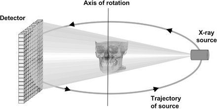
FIG. 14-2 Cone-beam Imaging Geometry.
A 3D cone (this example) or pyramidal (if collimation is rectangular) divergent x-ray beam is directed through a central object onto a detector (either solid-state flat panel or image intensifier/charge-coupled device). After a single two-dimensional projection is acquired by the detector, the x-ray source and detector rotate a small distance around a trajectory arc. At this second angular position another basis projection image or frame is captured. This sequence continues around the object for the entire 360 degrees (full trajectory) or a reduced or partial trajectory.
Cone-beam scanners use a two-dimensional digital array providing an area detector rather than a linear detector as CT does. This is combined with a three-dimensional (3D) x-ray beam with circular collimation so that the resultant beam is in the shape of a cone, hence the name “cone beam.” Because the exposure incorporates the entire region of interest (ROI), only one rotational scan of the gantry is necessary to acquire enough data for image reconstruction. Cone-beam geometry has inherent quickness in volumetric data acquisition and therefore the potential for significant cost savings compared with CT. CBCT produces an entire volumetric dataset from which the voxels are extracted. Voxel dimensions are dependent on the pixel size on the area detector. Therefore CBCT units in general provide voxel resolutions that are isotropic—equal in all three dimensions.
Image Acquisition
The cone-beam technique involves a rotational scan exceeding 180 degrees of an x-ray source and a reciprocating area detector moving synchronously around the patient’s head. During the rotation, many exposures are made at fixed intervals, providing single projection images known as basis images. These are similar to lateral cephalometric radiographic images, each slightly offset from one another. The complete series of basis images is referred to as the projection data. Software programs incorporating sophisticated algorithms including back-filtered projection are applied to these projection data to generate a 3D volumetric data set that can be used to provide primary reconstruction images in three orthogonal planes (axial, sagittal, and coronal).
There are four components to CBCT image acquisition:
The image generation and image detection specifications of currently available systems (Tables 14-1 and 14-2) reflect proprietary variations in these parameters.
TABLE 14-1
Representative Cone-Beam Computed Tomography Imaging Systems
| PRODUCT | DISTRIBUTOR |
| 3D Accuitomo/Veraviewpocs 3D | J. Morita Mfg. Corp. |
| CB MercuRay | Hitachi Medical Systems |
| Galileos | Sirona Dental Systems |
| GXCB-500 | Gendex Dental Systems |
| ILUMA Ultra Cone Beam CT/Kodak 9000 3D | Kodak Dental Systems |
| NewTom 3G (patient supine) NewTom VG (patient upright) |
AFP Imaging Corp. |
| Next Generation iCAT | Imaging Sciences International |
| Picasso Series–Trio/Pro/Master | Ashtel Dental/Vatech / E.Woo Technology |
| PreXion 3D | PreXion, Inc. |
| Promax 3D | Planmeca Oy |
| PSR9000N | Asahi Roentgen Corp./Belmont Corporation |
| Scanora 3D | Soredex, Inc. |
TABLE 14-2
Comparative Specifications of Food and Drug Administration–Approved Cone-Beam Computed Tomography Systems
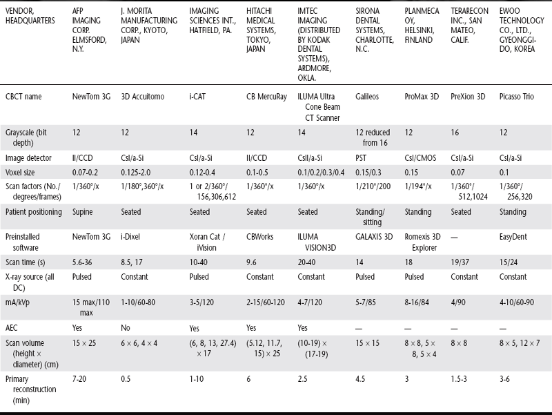
II/CCD, Area image intensifier/charge coupled device; CsI/a-Si, cesium iodide/amorphous silicon flat panel; CMOS, complementary metal oxide semiconductor; PST, proprietary Siemens Technology; AEC, automatic exposure control; min, minutes; cm, centimeter; s, seconds; No., number; DC, direct current; PD, photo diode; —, data unavailable at time of printing. Data current as of June 21, 2007.
X-RAY GENERATION
Although CBCT is technically simple in that only a single scan of the patient is made to acquire a data set, a number of clinically important parameters should be considered in x-ray generation.
Patient Positioning
CBCT can be performed with the patient in three possible positions: sitting, standing, and supine. Equipment that requires the patient to lie supine physically occupies a larger surface area or physical footprint and may not be accessible for patients with some physical disabilities. Standing units may not be able to be adjusted to a height to accommodate wheelchair-bound patients. Seated units are the most comfortable; however, fixed seats may also not allow scanning of physically disabled or wheelchair-bound patients. Because scan times are often greater than that used with panoramic imaging, perhaps more important than patient orientation is the head restraint mechanism used. With all systems it is important to immobilize the patient’s head because any movement degrades the final image.
X-ray Generator
During the scan rotation, each projection image is made by sequential single-image capture of the remnant x-ray beam by the detector. Technically, the easiest method of exposing the patient is to use a constant beam of radiation during the rotation and allow the x-ray detector to sample the attenuated beam in its trajectory. However, this results in a continuous radiation exposure to the patient, much of which does not contribute to the formation of the image. It is preferable to pulse the x-ray beam to coincide with the detector sampling. This means that actual exposure time is markedly less than scanning time. This technique reduces patient radiation dose considerably.
The ALARA (As Low As Reasonably Achievable) principle of dose optimization necessitates that CBCT exposure factors should be adjusted on the basis of patient size. This can be achieved by appropriate selection of either tube current (milliamperes [mA]), tube voltage (kilovolts peak [kVp]), or both. On some CBCT units both kVp and mA are automatically modulated in near real time by a feedback mechanism detecting the intensity of the transmitted beam, a process known generically as automatic exposure control. On others, exposure settings are automatically determined by the initial scout exposure. This feature is highly desirable because it is operator independent. The variation in exposure parameters together with the presence of pulsed x-ray beam and size of the image field are the primary determinants of patient exposure.
Scan Volume
The dimensions of the field of view or scan volume able to be covered are primarily dependent on the detector size and shape, beam projection geometry, and the ability to collimate the beam. The shape of the scan volume can be either a cylinder or spherical. Collimating the primary x-ray beam limits x-radiation exposure to the ROI. Limiting field size therefore ensures that an optimal field of view can be selected for each patient on the basis of individual needs. Scanning of the entire craniofacial region is difficult to incorporate into cone-beam design because of the high cost of large area detectors. One manufacturer has expanded the scan volume height by software addition of two rotational scans to produce a single volume with a 22-cm height.
Scan Factors
The speed with which individual images are acquired is called the frame rate and is measured in frames, projected images, per second. The maximum frame rate of the detector and rotational speed determines the number of projections that may be acquired. The number of projection images comprising a single scan may be fixed or variable. With a higher frame rate, more information is available to reconstruct the image; therefore, primary reconstruction time is increased. However, higher frame rates increase the signal-to-noise ratio, producing images with less noise. In the maxillofacial region, another advantage of a higher frame rate is that it reduces metallic artifact. Note that higher frame rates are usually accomplished with a longer scan time and hence higher patient dose.
Most CBCT imaging systems use a complete circular trajectory or a scan arc of 360 degrees to acquire projection data. This physical requirement is usually necessary to produce adequate projection data for 3D reconstruction. However, it is theoretically possible to reduce the completeness of the scanning trajectory to less than a full circle and still reconstruct a volumetric data set. This approach potentially reduces the scan time and is mechanically easier to perform.
It is desirable to reduce CBCT scan times to as short as possible to reduce motion artifact resulting from subject movement. This can be substantial and may be a limiting factor in voxel resolution. Decreased scanning times may be achieved by increasing the detector frame rate, reducing the number of projections, or reducing the scan arc. The latter two possibilities produce data with higher noise, whereas the first is optimal.
IMAGE DETECTION
Current CBCT units can be divided into two groups on the basis of detector type: image intensifier tube/charge-coupled device combination or flat-panel imager. The former configuration comprises an x-ray image intensifier tube coupled to a charge-coupled device with a fiber optic coupling. Flat-panel imaging consists of detection of x rays with an “indirect” detector that is based on a large area solid-state sensor panel coupled to an x-ray scintillator layer (see Chapter 7). The most common flat-panel configuration consists of a cesium iodide scintillator applied to a thin film transistor made of amorphous silicon.
Voxel Size
The principal determinants of nominal voxel size in CBCT are the x-ray tube focal spot size, x-ray geometric configuration, and the matrix and pixel size of the solid state detector. Both the focal spot size and the geometric configuration of the x-ray source determine the degree of geometric unsharpness, a limiting factor in spatial resolution. However, the cost of x-ray tubes, and therefore of the CBCT unit, increases substantially with smaller focal spot size. Reducing the object-to-detector distance and increasing source-to-object distance also minimizes geometric unsharpness. In maxillofacial CBCT the detector position is limited because it must be located far enough from the patient’s head so that it freely rotates and clears the patient’s shoulders. Limitations also exist in extending the source-to-object distance because this increases the size of the CBCT unit. However, reducing source-to-object distance produces a magnified projected image on the detector, increasing potential spatial resolution.
Grayscale
The ability of CBCT to display differences in attenuation is related to the ability of the detector to detect subtle contrast differences. This parameter is called the bit depth of the system and determines the number of shades of gray available to display the attenuation. At the time of writing, all available CBCT units used detectors capable of recording grayscale differences of 12 bits or higher. If a 12-bit detector (212) is used to define the scale, 4096 shades are available to display contrast. Although higher bit-depth images in CBCT are possible, this added information comes at the expense of increased computational time and substantially larger file sizes.
RECONSTRUCTION
Once the basis projection frames have been acquired, it is necessary to process these data to create the volumetric data set. This process is called primary reconstruction. Although a single cone-beam rotation may take less than 30 seconds, it produces 100 to more than 600 individual projection frames, each with more than a million pixels with 12 to 16 bits of data assigned to each pixel. The reconstruction of these data is computationally complex. To facilitate data handling, data are usually acquired by one computer (acquisition computer) and transferred by an Ethernet connection to a processing computer (workstation). In contrast to conventional CT, cone-beam data reconstruction is performed by personal computer–based rather than workstation platforms.
Reconstruction times vary depending on the acquisition parameters (voxel size, size of the image field, and number of projections), hardware (processing speed, data throughput from acquisition to workstation computer), and software (reconstruction algorithms) used. Reconstruction should be accomplished in an acceptable time (less than 5 minutes) to complement patient flow.
The reconstruction process consists of two stages (Fig. 14-3):
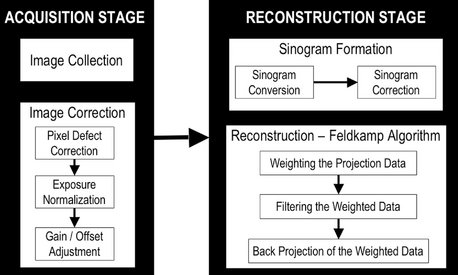
FIG. 14-3 Image acquisition and Reconstruction.
The acquisition stage involves acquisition of individual basis projections and subsequent modification of these images to correct for inconsistencies. Image correction is sequential and consists of the removal of signal voids from individual or linear pixel defects, image normalization by histogram equalization so that a full range of voxel intensity values are used, and removal of inherent electronic detector artifacts. After correction, images undergo reconstruction that includes converting the corrected basis projection images into sinograms and application of the Feldkamp reconstruction to the corrected sinograms, which includes weighting the information according to location, applying specific filters to the image, and finally use of back-projection techniques to reconstitute the image.
1. Acquisition stage. This stage is performed at the acquisition computer. Once the multiple planar projection images are acquired, these images must be corrected by for inherent pixel imperfections and uneven exposure. Image calibration should be performed routinely to remove these defects.
2. Reconstruction stage. The remaining data-processing steps are performed on the reconstruction computer. The corrected images are converted into a special representation called a sinogram, a composite image developed from extracting a row of pixels from each projection image. Therefore the first sinogram will comprise a series of the first rows from each projection. If there are 300 projections, then the sinogram will have 300 rows. This process is referred to as the radon transformation. The resulting image comprises multiple sine waves of different amplitude. The sinogram is then reconstructed with a filtered back-projection algorithm for CBCT-acquired volumetric data called the Feldkamp algorithm. Once all slices have been reconstructed, they are combined into a single volume for visualization.
DISPLAY
The volumetric data set is a compilation of all available voxels and, for most CBCT devices, is presented to the clinician on screen as secondary reconstructed images in three orthogonal planes (axial, sagittal, and coronal), usually at a thickness defaulted to the native resolution (Fig. 14-4). Optimum visualization of orthogonal reconstructed images is dependent on the adjustment of window level and window width to favor bone and the application of specific filters.
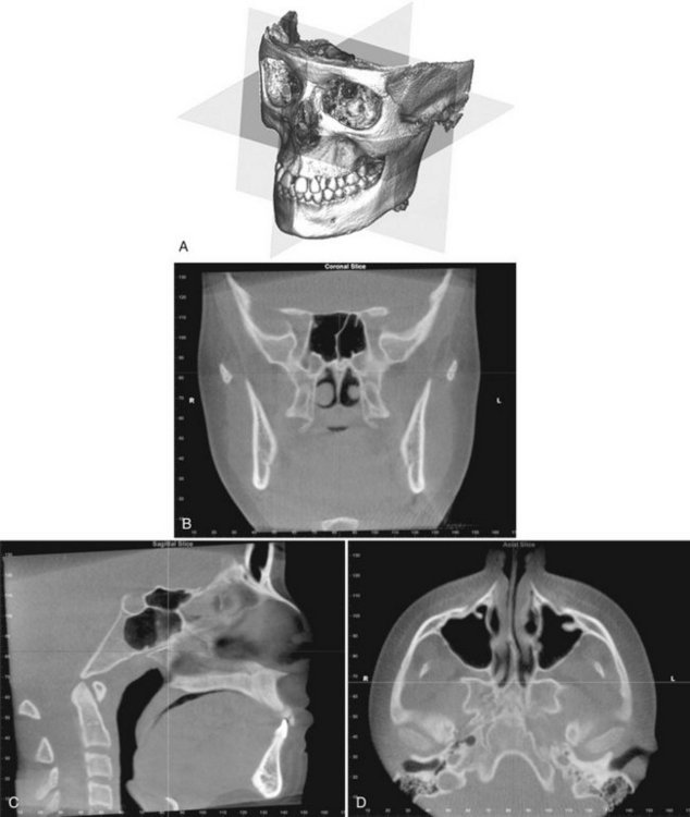
FIG. 14-4 Standard Display Modes of CBCT Volumetric Data.
A, Volumetric 3D representation of hard tissue showing the three orthogonal planes in relation to the reconstructed volumetric data set: coronal, sagittal, and axial. Each orthogonal plane has multiple thin slice sections in each plane. B, Representative coronal image. C, Representative sagittal image. D, Representative axial image. (Images produced using Dolphin 3D, Chatsworth, Calif.)
Multiplanar Reformation
Because of the isotropic nature of the volumetric dataset, data sets can be sectioned nonorthogonally. Most software provides for various nonaxial two-dimensional images, referred to as multiplanar reformation (MPR). Such MPR modes include oblique, curved planar reformation and, serial transplanar reformation (Fig. 14-5). Because of the large number of component orthogonal images in each plane and the difficulty in relating adjacent structures, two methods have been developed to visualize adjacent voxels.
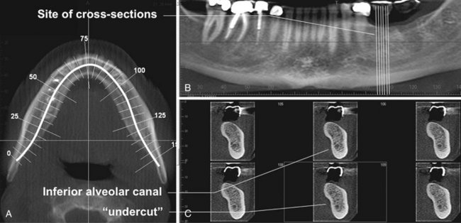
FIG. 14-5 Multiplanar Reformation.
A thick axial image simulating an occlusal image (A) with an MPR oblique curved line (white solid) and resultant “panoramic” (B) and serial cross-sectional 1-mm-thick images (C) of a potential implant site in the lower left mandible. The axial and panoramic images are used as reference images to show the location of the cross-sectional images. The cross-sectional images demonstrate the amount of undercut and location of the inferior alveolar canal.
Most simply, any multiplanar image can be “thickened” by increasing the number of adjacent voxels included in the display. This creates an image slab that represents a specific volume of the patient, referred to as a ray sum. Full-thickness perpendicular ray sum images can be used to generate simulated projections such as lateral cephalometric images (Fig. 14-6). Unlike conventional radiographs, these ray sum images are without magnification and parallax distortion. However, this technique uses the entire volumetric data set and interpretation suffers from the problems of “anatomic noise”—the superimposition of multiple structures.
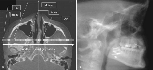
FIG. 14-6 Ray Sum Images.
An axial projection (A) is used as the reference image. A section slice is identified that, in this case, corresponds to the mid sagittal plane and the thickness of this increased to include both left and right sides of the volumetric data set. As the thickness of the “slab” increases, adjacent voxels representing elements such as air, bone, and soft tissues are added. The resultant image generated (B) from a full-thickness ray sum provides a simulated lateral cephalometric image.
Three-Dimensional Volume Rendering
Volume rendering refers to techniques that allow the visualization of 3D data by integration of large volumes of adjacent voxels and selective display. Two specific techniques are available.
Indirect volume rendering is a complex process requiring selection of the intensity or density of the grayscale level of the voxels to be displayed within an entire data set (called “segmentation”). This is technically demanding and computationally difficult, requiring specific software; however, it provides a volumetric surface reconstruction with depth (Fig. 14-7).
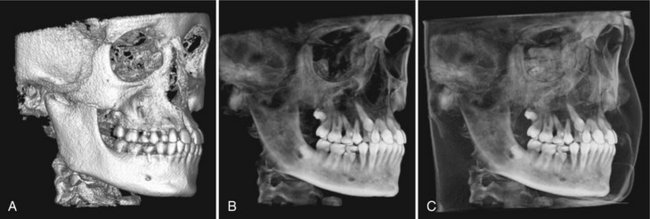
FIG. 14-7 3D Volumetric Surface Rendering.
Manual segmentation is often accomplished by an adjustable scale determining the upper and lower limit and range of intensity values to include in the segmentation. The visual result of changes in this scale is displayed in “real time” so that the effects of incremental changes can be visualized. The segmentation may be optimized to reveal the objects of interest including (A) bone as a solid surface or shaded surface display, (B) bone and the dentition under the bone as a transparency using volumetric imaging, or (C) bone, the dentition, and the soft tissue surface using volumetric imaging. (Segmentation performed with Dolphin 3D, Chatsworth, Calif.)
Direct volume rendering is a much simpler process. The most common technique is maximum intensity projection (MIP). MIP visualizations are achieved by evaluating each voxel value along an imaginary projection ray from the observer’s eyes within a particular volume of interest and then representing only the highest value as the display value. Voxel intensities that are below an arbitrary threshold are eliminated (Fig. 14-8).
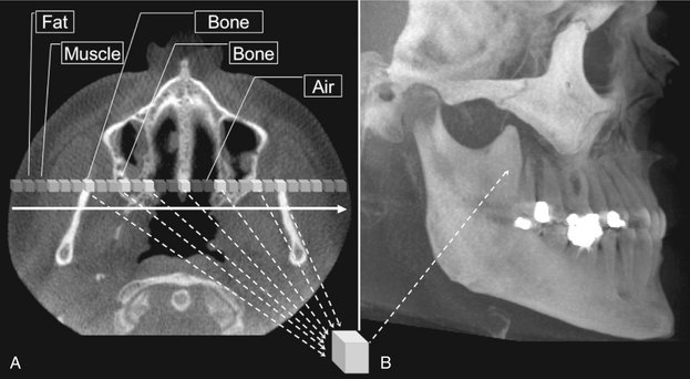
FIG. 14-8 Maximum Intensity Projection.
This method produces a “pseudo” 3D image by evaluating each voxel value along an imaginary projection ray from the observer’s eyes within the data set and then representing only the highest value as the display value. In this example, an axial projection (A) is used as the reference image. A projection ray is identified throughout the entire volumetric data set along which individual voxels are identified, each with varying grayscale intensity corresponding to various tissue densities such as fat, muscle, air, and bone. The MIP algorithm selects only those values along the projection ray that have the highest values (usually corresponding to bone) and represents this as only one pixel on the resultant image (B).
Clinical Considerations
For each image acquisition there are procedural steps and numerous operator-controlled exposure parameters that must be specified. Consistent and methodic imaging technique minimizes patient radiation exposure and optimizes the resultant image quality.
PATIENT SELECTION CRITERIA
Cone beam exposure provides a radiation dose to the patient higher than those of other dental radiographic procedures. Accordingly, the principal tenet of the ALARA principle must be applied: there should be justification of the exposure to the patient so that the total potential diagnostic benefits are greater than the individual detriment radiation exposure might cause. Currently CBCT is most commonly used in the assessment of pathologic conditions and structural maxillofacial deformity, the preoperative assessment of orthodontics, and in the assessment of available bone for implant placement. It is advisable that the indication for the CBCT examination be documented by entry in the patient’s chart or on the written request or prescriptive order for the CBCT examination.
PATIENT PREPARATION
Patients should be escorted into the scanner unit and before head stabilization provided with appropriate personal radiation barrier protection. Although the mandatory use of these devices is regulated by regional (state) or federal legislation, it is recommended that at least a leaded torso apron be applied correctly (above the collar) to the patient. This is particularly advisable for pregnant patients and for children. It is highly recommended that a lead thyroid collar also be used, provided that this will not interfere with the scan, to reduce thyroid exposure.
Each CBCT unit has a unique method of head stabilization, varying from chin cups to posterior or lateral head supports to head restraints. Patient motion can be minimized by application of one or more methods simultaneously. Image quality is severely degraded by head movement, so it is important to obtain patient compliance.
Alignment of the area of interest with the x-ray beam is critical in imaging the appropriate field, thereby reducing patient radiation exposure and optimizing image quality by reducing scattered radiation. Often facial topographic reference planes (e.g., the mid sagittal plane, Frankfort horizontal) or internal references (e.g., occlusal plane, palatal plane) are adjusted to coincide or be aligned with external laser lights to position the patient correctly.
Immediately before the scan, the patient should be asked to remove all metallic objects form the head and neck areas. This includes eyeglasses, jewelry (including earrings and piercings), and metallic partial dentures. It is not necessary to remove plastic completely removable prostheses. Unless specifically indicated otherwise (e.g., closed temporomandibular [TMJ] views or orthodontic views), it is desirable that the dentition be separated but held together firmly during the scan. This can be performed with a tongue depressor or cotton rolls. Separation of the teeth is particularly useful in single arch scans where scatter from metallic restorations in the opposing arch can be reduced. The patient should be directed to remain as still as possible before exposure, to breathe slowly through the nose, and to close the eyes. This latter suggestion reduces the possibility of the patient moving as a result of following the detector as it passes in front of the face.
IMAGING PROTOCOL
An imaging protocol is a set of technical exposure parameters for CBCT dependent on the specified purpose of the examination. An imaging protocol is developed to produce images of optimal quality with the least amount of radiation exposure to the patient. For specific cone beam units, manufacturer-provided imaging protocols are usually available. Most commonly they involve modifications in imaging field, number of basis projections, and voxel resolution. Operators should be aware of the effects of all parameters on image quality and patient dose when choosing imaging protocols.
Voxel Size
The voxel size with which projection images are acquired varies from manufacturer to manufacturer principally on the basis of the matrix size of the detector and projection geometry. In addition, CBCT units may offer a selection of voxel sizes. For these choices the image detector collects information over a series of pixels in the horizontal and vertical directions and averages the data. This collation or pixel binning results in a substantial reduction in data processing, reducing secondary reconstruction times. Therefore voxel size should be specified as either acquisition or reconstruction. Generally, decreasing voxel size increases spatial resolution, but because of the pixel fill factor of a particular flat panel, a higher radiation dose may be required.
Scan Time and Number of Projections
Adjusting the frame rate to increase the number of basis image projections provides reconstructed images with fewer artifacts and better image quality (Fig. 14-9). However, increasing the number of projections increases patient radiation exposure proportionately.
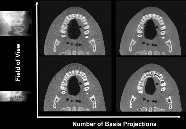
FIG. 14-9 Pictorial Plot of the Effect of Number of Basis Projection Images and Size of Fov on Image Quality.
Increasing number of projections in one 360-degree scan (x-axis) provides more data and reduces image noise; however, it increases patient dose proportionately. Reducing the number of projections creates undersampling and produces streaks. Minimizing the FOV reduces patient exposure and resultant scatter radiation and decreases image noise.
Scanning Trajectory
Reconstructed images from incomplete, limited, or truncated scanning trajectories may suffer from strong limited-angle artifacts because of missing information. Images created with incomplete scanning arcs suffer from greater peripheral unidirectional streaking artifacts and more pronounced mid plane cupping and photon starvation artifacts. Missing data can be somewhat compensated for with a number of approaches, including use of statistical knowledge of the patient’s anatomy and use of a number of algorithm projection completion techniques.
Field of View
Collimation of the CBCT primary x-ray beam enables limitation of the x radiation to the area of interest. This functionality provides dose savings by limiting the irradiation field to fit the field of view (FOV), with a reduced exposure dose to the patient and improved image quality because of reduced scattered radiation (see Fig. 14-9).
IMAGE OPTIMIZATION
Most programs offer the user means to adjust brightness, contrast, and edge sharpening. To optimize image presentation and facilitate diagnosis, it is necessary to adjust contrast (window) and brightness (level) parameters to favor bony structures. Great variability exists in cone beam imaging between CBCT units and within the same unit depending on the number of scans performed. Although CBCT proprietary software may provide for window/level presets, it is advisable that this be adjusted for each scan. After these parameters are set, further enhancements can be performed by the application of sharpening, filtering, and edge algorithms. The use of these functions must be weighed against the visual effects of increased noise in the image (Fig. 14-10).
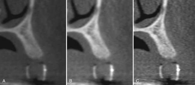
FIG. 14-10 Effect of Image Enhancement on CBCT Images.
The visual effect of three sequential adjustments on corrected MPR cross-sectional images. A, Default image after interpolation algorithm—smoothens edges of cortical bone but adds blur to high-contrast structures. B, Adjustment of window level and width to bone preset (W/L: 3000/500). C, Addition of mild sharpen algorithm. (Images captured with i-CAT, ISI, Hatfield, Pa, created with XoranCat software, Xoran Technologies, Inc., Ann Arbor, Mich.)
REPORTS
Cone-beam imaging comprises not only the technical component of patient exposure but a responsibility for interpreting the resultant volumetric data set. Documentation of an imaging examination is an important part of a patient’s medical record. The mechanics of image reporting include the development of a series of images formatted to display the condition/region appropriately (image report) and a cognitive interpretation of the significance of the imaging findings (interpretive report).
ARCHIVING, EXPORT, AND DISTRIBUTION
The process of CBCT imaging produces two data products, the volumetric image data from the scan and the image report generated by the operator. Both sets of data must be archived and distributed. Scan data backup is usually performed in its native or proprietary image format. However, export of image data is usually in the DICOM (Digital Imaging and Communications in Medicine) file format standard for use in specialized software.
Image Artifacts
The fundamental factor that impairs CBCT image quality is image artifact. An artifact is any distortion or error in the image that is unrelated to the subject being studied. Artifacts can be classified according to their etiology.
ACQUISITION ARTIFACTS
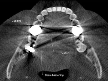
Artifacts can arise from limitations in the physical processes involved in the acquisition of CBCT data. As an x-ray beam passes through an object, lower energy photons are absorbed in preference to higher energy photons. This phenomenon, called beam hardening, results in two types of artifact: (1) distortion of metallic structures as a result of differential absorption, known as a cupping artifact, and (2) streaks and dark bands that can appear between two dense objects (Fig. 14-11). In clinical practice it is advised to reduce the field size, modify patient position, or separate the dental arches to avoid scanning regions susceptible to beam hardening (e.g., metallic restorations, dental implants).
PATIENT-RELATED ARTIFACTS
Patient motion can cause misregistration of data, which appear as unsharpness in the reconstructed image. This can be minimized by restraining the head and using as short a scan time as possible. It is also important to remove metallic objects such as jewelry before scanning because of the beam-hardening artifacts described previously.
SCANNER-RELATED ARTIFACTS
Typically scanner-related artifacts present as circular or ring streaks resulting from imperfections in scanner detection or poor calibration (Fig. 14-12). Either of these problems will result in a consistently and repetitive reading at each angular position of the detector, resulting in a circular artifact.
CONE BEAM–RELATED ARTIFACTS
The beam projection geometry of CBCT and image reconstruction method produce three types of cone-beam–related artifacts:
Partial volume averaging is a feature of both conventional fan and CBCT imaging. It occurs when the selected voxel size of the scan is larger than the size of the object being imaged. For instance, a voxel 1 mm on a side may contain both bone and adjacent soft tissue. In this case, the displayed pixel is not representative of either bone or soft tissue but rather becomes a weighted average of the different brightness values. Boundaries in the resultant image may present with a “step” appearance or homogeneity of pixel intensity levels. Partial volume averaging artifacts occur in regions where surfaces are rapidly changing in the z direction, for example, in the temporal bone. Selection of the smallest acquisition voxel can reduce the presence of these effects.
Undersampling of the object can occur when too few basis projections are provided for image reconstruction. A reduced data sample leads to misregistration, sharp edges, and noisier images as a result of aliasing, which appear as fine striations in the image (see Fig. 14-9). Because increasing the number of basis projections is proportional to patient exposure, the importance of this artifact should be considered in relation to the diagnostic information.
The cone beam effect is a potential source of artifacts, especially in the peripheral portions of the scan volume. Because of the divergence of the x-ray beam as it rotates around the patient in a horizontal plane, structures at the top or bottom of the image field will only be exposed when the x-ray source is on the opposite side of the patient. This results in image distortion, streaking artifacts, and greater peripheral noise. This effect is minimized by manufacturers incorporating various forms of cone-beam reconstruction. Clinically it can be reduced by positioning the region of interest in the horizontal plane of the x-ray beam.
Strengths and Limitations
Cone-beam imaging has a number of features that make it suitable for many dental applications, but it also has a number of limitations.
STRENGTHS
CBCT equipment has a greatly reduced size and physical footprint compared with conventional CT and it is approximately one fourth to one fifth the cost. Both these features make it available for the dental office.
High-Speed Scanning
Compared with conventional CT, the time for the CBCT scanning is substantially reduced and, for most equipment, is less than 30 seconds. This is because the CBCT requires only a single scan to capture the necessary data compared with conventional CT scanners, where several fan beam rotations are required to complete the imaging of an object.
Submillimeter Resolution
Currently all CBCT units use megapixel solid-state devices for x-ray detection. These devices provide submillimeter pixel resolution of component basis projection images. The size of these voxels determines the resolution of the image. CBCT produces images with submillimeter voxel resolution ranging from 0.4 mm to as low as 0.125 mm. Because of this characteristic, coronal and subsequent MPR of CBCT data has the same resolution as axial data. This level of spatial resolution is applicable for maxillofacial applications.
Low Patient Radiation Dose
Published reports indicate that the effective dose (2005 International Committee on Radiation Protection) for various CBCT devices ranges from 52 to 1025 microsieverts (μSv) depending on the type and model of CBCT equipment and imaging protocol used. These values are approximately equivalent to 4 to 77 digital panoramic radiographs (approximately 13.3 μSv) or 5 to 103 days equivalent per capita background dose (approximately 3600 μSv in the United States). Patient radiation dose can be lowered by collimating the beam, elevating the chin, and using thyroid and cervical spine shielding. CBCT provides a range of dose reductions of between 96% and 51% compared with conventional head CT (range 1400 to 2100 μSv).
Interactive Analysis
CBCT data reconstruction and viewing is performed natively by use of a personal computer. In addition, some manufacturers provide software with extended functionality for specific applications such as implant placement or orthodontic analysis. Finally, the availability of cursor-driven measurement algorithms provides the practitioner with an interactive capability for real-time dimensional assessment, annotation, and measurements.
LIMITATIONS
Although there has been enormous interest in CBCT, this technology has limitations related to the cone beam projection geometry, detector sensitivity, and contrast resolution that produce images that lack the clarity and utility of conventional CT images.
Image Noise
The cone beam projection acquisition geometry results in a large volume being irradiated with every basis image projection. A large portion of the photons undergo Compton scattering interactions and produce scattered radiation. Most scattered radiation is produced omnidirectionally and recorded by pixels on the cone beam area detector; it does not reflect the actual attenuation of an object along a specific path of the x-ray beam. This additional recorded x-ray attenuation, reflecting nonlinear attenuation, is called noise and contributes to image degradation. The amount of scattered radiation is generally proportional to the total mass of tissue contained within the primary x-ray beam; this increases with increasing object thickness and field size. The contribution of this scattered radiation to production of the CBCT image may be greater than the primary beam. In clinical applications, the scatter-to-primary ratios are about 0.01 for single-ray CT and 0.05 to 0.15 for fan-beam and spiral CT and may be as large as 0.4 to 2 in CBCT.
Additional sources of image noise in CBCT are variations in the homogeneity of the incident x-ray beam (quantum mottle) and added noise of the detector system (electronic). The inhomogeneity of x-ray photons depends on the number of the primary and scattered x-ray absorbed, the primary and scattered x-ray spectra incident on the detector and the number of views (projections). Electronic noise is due to the inherent degradations of the detector system related to the x-ray absorption efficiency of energy at the detector.
In addition, because of the increased divergence of the x-ray beam over the area detector, there is a pronounced heel effect. This produces a large variation or nonuniformity of the incident x-ray beam on the patient and resultant nonuniformity in absorption with greater signal-to-noise ratio (noise) on the cathode side of the image relative to the anode side.
Poor Soft Tissue Contrast
Contrast is the spatial variation of the x-ray photon intensities that are transmitted through the patient; contrast thus gives a measure of difference between regions in an image. The variation in transmitted intensities is a result of differential attenuation of x rays by tissues that differ in density, atomic number, and thickness. Two principal factors limit the contrast resolution of CBCT. Although scattered radiation contributes to increased noise of the image, it is also a significant factor in reducing the contrast of the cone beam system. X-ray scatter reduces subject contrast by adding background signals that are not representative of the anatomy, thereby reducing image quality.
Second, there are numerous inherent flat panel detector-based artifacts that affect its linearity or response to x radiation. Saturation (nonlinear pixel effects above a certain exposure), dark current (charge that accumulates over time with or without exposure), and bad pixels (pixels that do not react to exposure) contribute to nonlinearity. In addition, the sensitivity of different regions of the panel to radiation (pixel-to-pixel gain variation) may not be uniform over the entire region.
Specific Applications in Dentistry
CBCT technology has had a substantial impact on maxillofacial imaging. It has been applied to diagnosis in all areas of dentistry and is now expanding into treatment applications. CBCT should not be considered a replacement for panoramic or conventional projection radiographic applications but rather as a complementary modality for specific applications.
IMPLANT SITE ASSESSMENT
Perhaps the greatest impact of CBCT has been on the planning of dental implant placements. CBCT provides cross-sectional images of the alveolar bone height, width, and angulation and accurately depicts vital structures such as the inferior alveolar dental nerve canal in the mandible or the sinus in the maxilla. The most useful series of images for implant site assessment include the axial, reformatted panoramic, and serial transplanar images at the specific location (Fig. 14-13). In many instances a diagnostic stent is made with radiographic markers and inserted at the time of the scan (Fig. 14-14). This provides a precise reference of the location of the proposed implants or teeth. DICOM data can be imported into third-party software applications that provide many useful tools that can be used to assess and plan both the surgical and prosthetic components of implant therapy. In addition, the data set may then be used to construct a surgical implant guidance stent to facilitate the precise placement of implants.
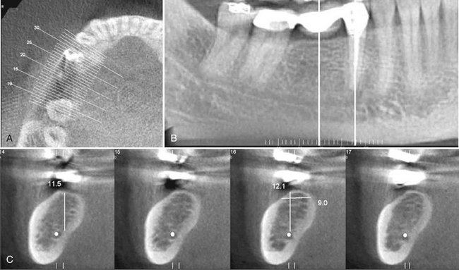
FIG. 14-13 CBCT for Implant Site Assessment.
A curved planar MPR is accomplished by aligning the long axis of the imaging plane with the dental arch (A), providing a region panorama-like thin-slice image (B). In addition, serial thin-slice transplanar images are often generated (C), useful in the assessment of specific morphologic features such as the location of the inferior alveolar canal (shown with a white dot) for implant site assessment and for allowing measurement of the available alveolar bone height and width. (Images captured and created with Newtom 3G, AFP Imaging Corp., Elmsford, N.Y.)
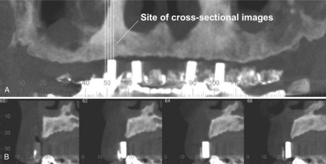
FIG. 14-14 Use of a Diagnostic Stent.
Stents provide fiducial radiographic landmarks that can be used to correlate proposed clinical location and angulation of implants with the available alveolar bone. The panoramic projection (A) provides an overview of location, whereas serial cross-sectional images (B) indicate alveolar bone height. In this example, the four transplanar images of the maxillary right canine region indicate that the proposed placement is too far buccal and too perpendicular to engage the available bone. (Images captured with i-CAT, ISI, Hatfield, Pa, created with XoranCat software, Xoran Technologies, Inc., Ann Arbor, Mich.)
ORTHODONTICS AND THREE-DIMENSIONAL CEPHALOMETRY
CBCT imaging is being used in the diagnosis, assessment, and analysis of maxillofacial orthodontic and orthopedic anomalies. CBCT provides display of the position of impacted and supernumerary teeth and their relationships to adjacent roots or other anatomic structures. This facilitates surgical exposure and planning of subsequent movement. Also, information regarding palatal morphologic features and dimensions, tooth inclination and torque, root resorption, and available alveolar bone width for buccolingual movement of teeth can be obtained. CBCT also provides adequate visualization of the TMJ, the pharyngeal airway space, and soft tissue relationships.
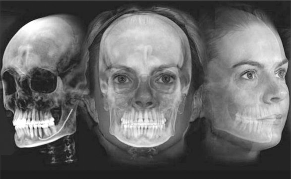
Perhaps the greatest potential use of CBCT in orthodontics is that it is capable of providing both conventional two- and three-dimensional cephalometric images in one acquisition. CBCT data sets can be manipulated by the ray sum technique to generate simulated panoramic, lateral, submentovertex, and posteroanterior cephalometric images (Fig. 14-15). Alternatively, it is possible to extract the topographic features of the skull and air/soft tissue interfaces in high detail by using a variety of orthodontic-centered products. There are numerous potential benefits to 3D cephalometry including accuracy of linear measurements, visual demonstration of dentoskeletal relationships and facial esthetics, and the potential for assessment of growth and development (Fig. 14-16).
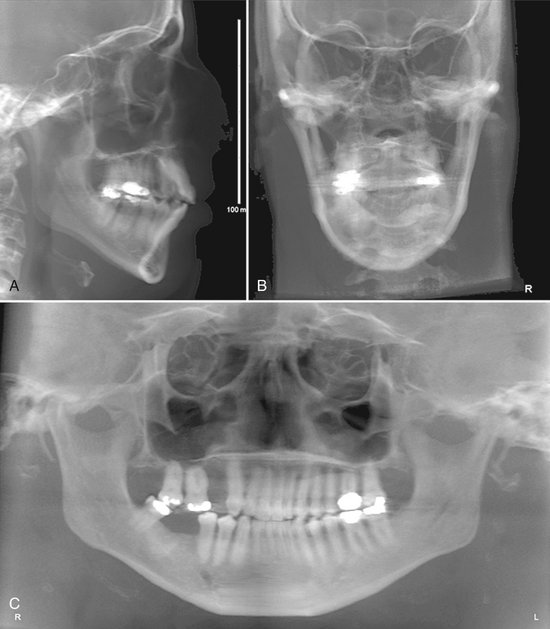
FIG. 14-15 Two-dimensional Projections Generated with Cone Beam Data Set.
This patient had an asymmetry of one side of the face. Ray sum reformation of the CBCT data was performed to provide multiple conventional images such as the lateral cephalometric (A), frontal cephalometric or posteroanterior (B), and panoramic (C) projections. (Images generated with Dolphin 3D, Chatsworth, Calif.)
LOCALIZATION OF THE INFERIOR ALVEOLAR CANAL
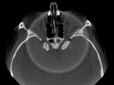
The relationship of the inferior alveolar canal to the roots of mandibular third molar teeth is of importance when attempting to minimize the likelihood of nerve damage that may lead to permanent loss of sensation to one side to the lower lip. Thus accurate assessment of the position of the canal in relation to the impacted third molar may reduce injuries to this nerve. Traditional panoramic imaging may be adequate when the third molar is clear of the canal, but in the case of radiographic superimposition it is advisable to use a 3D imaging approach. This can be achieved at comparatively low radiation dose with CBCT combined either with the proprietary software accompanying the imaging device or with a third-party diagnostic software (Fig. 14-17).
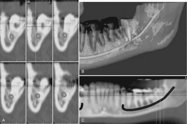
FIG. 14-17 Region reconstructed.
A, Cross-sectional views. B, Third-party software used to demonstrate location of inferior alveolar canal to an impacted third molar in 3D images. C, MPR reformatted images using proprietary software demonstrating proximity of the root of an unerupted and impacted third molar associated with the inferior alveolar canal. (Images created with Simplant, Materialise, Leuven, Belgium, courtesy 3DDX, Brighton, Mass.)
TEMPOROMANDIBULAR JOINT
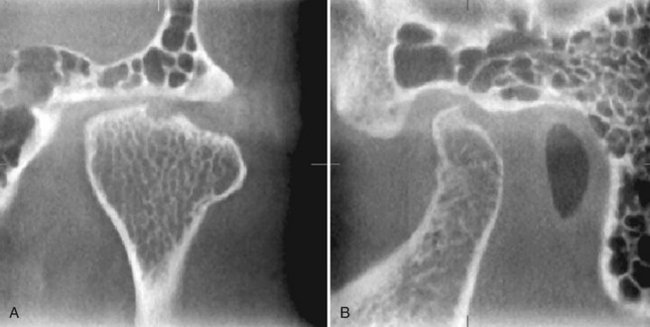
CBCT provides multiplanar and potentially 3D images of the condyle and surrounding structures to facilitate analysis and diagnosis of bone morphologic features, joint space and dynamic function, critical keys to providing appropriate treatment outcomes in patients with TMJ signs and symptoms. Imaging can depict the features of degenerative joint disease (Fig. 14-18), developmental anomalies of the condyle, ankylosis, and rheumatoid arthritic disease. Appropriate imaging protocols should include reformatted panoramic and axial reference images, corrected parasagittal and paracoronal transerial slices, and for those cases in which asymmetry or surgery is contemplated, 3D reconstructions.
CONDITIONS OF THE MAXILLOFACIAL COMPLEX
CBCT can assist in the assessment of many conditions of the jaws, most notably dental conditions such as impacted canines and supernumerary teeth, fractured or split teeth, periapical lesions, and periodontal disease (Fig. 14-19). Benign calcifications (e.g., tonsilloliths, lymph nodes, salivary gland stones) can also be identified by location and differentiated from potentially significant calcifications of the arteries such as carotid artery calcifications or veins (e.g., phleboliths). Although CBCT does not provide suitable soft tissue contrast to distinguish the contents of paranasal opacifications, the morphologic characteristics and extent of these lesions are particularly well seen (e.g., mucous extravasation cyst).
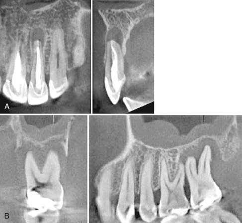
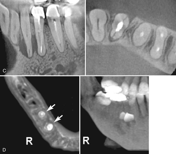
FIG. 14-19 Regional cone-beam Imaging.
Numerous dental conditions can be demonstrated in high resolution with regional CBCT, including (A) periapical condition, (B) periodontal and periapical disease, (C) root fracture and associated alveolar bone loss, and (D) supernumerary teeth. (Images A-C captured with 3DX Accuitomo, J. Morita Mfg. Corp., Kyoto, Japan. D captured with i-CAT, ISI, Hatfield, Pa., created using XoranCat software, Xoran Technologies, Inc., Ann Arbor, Mich.)
Most important, the location, size, shape, extent, and full involvement of jaw conditions can be visualized with a combination of two- and three-dimensional images. CBCT has been found to be particularly useful for trauma (Fig. 14-20) and for visualizing the extent and degree of involvement of osteomyelitis.
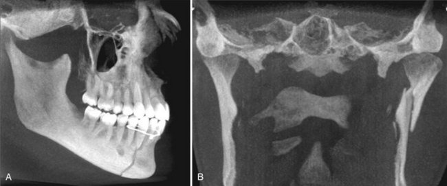
FIG. 14-20 Fracture demonstration.
Use of MIP projections in the assessment of complex mandibular fractures. A, an oblique thin slab MPR image with a MIP application demonstrates a simple, slightly displaced fracture of the right parasymphyseal region, whereas, B, a coronal thin slab MIP image demonstrates a comminuted displaced left subcondylar neck fracture. (Images captured with i-CAT, ISI, Hatfield, Pa., created using XoranCat software, Xoran Technologies, Inc., Ann Arbor, Mich.)
RAPID PROTOTYPING
Rapid prototyping (RP) is broad term used to describe a group of related processes and techniques that are used to fabricate physical scale models directly from 3D computer-assisted design data. The purpose of RP in maxillofacial imaging is to create a life-size, dimensionally accurate model of an anatomic structure. These models are also referred to as biomodels. DICOM data imported to proprietary software can be used to compute 3D images generated by thresholding the intensity of the voxel values to be displayed and segmenting these from the background. The models produced are used for presurgical planning of a number of complex maxillofacial surgical cases, including craniofacial reconstruction for correction of deformity caused by trauma, tumor resection, distraction osteogenesis, and, more widely, dental implants (Fig. 14-21). The models provide the practitioner with a higher level of confidence before he or she performs a surgical procedure and may reduce surgical and anesthetic time.
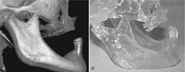
FIG. 14-21 Rapid prototype.
A, 3D volumetric reconstruction from CBCT data. B, Rapid prototype constructed model of patient with right-sided chemically induced osteonecrosis. Modeling was performed before surgical resection and reconstruction to provide addition of bone in the right mandibular premolar area. (Volumetric rendering performed with 3DVR, AlloVision LLC, Greenville, S.C.)
Conclusion
CBCT imaging systems have been recently been introduced for imaging hard tissues of the maxillofacial region. CBCT is capable of providing accurate, submillimeter resolution images at shorter scan times, lower dose, and lower costs compared with medical fan-beam CT. Increasing availability of this technology provides the practitioner with an imaging modality capable of providing a 3D representation that is extending maxillofacial imaging from diagnosis to image guidance of operative and surgical procedures.
Dula, K, Mini, R, van der Stelt, PF, et al. Hypothetical mortality risk associated with spiral computed tomography of the maxilla and mandible. Eur J Oral Sci. 1996;104:503–510.
Ludlow, JB, Davies-Ludlow, LE, Brooks, SL. Dosimetry of two extraoral direct digital imaging devices: NewTom cone beam CT and Orthophos Plus DS panoramic unit. Dentomaxillofac Radiol. 2003;32:229–234.
Ludlow, JB, Davies-Ludlow, LE, Brooks, SL, et al. Dosimetry of 3 CBCT devices for oral and maxillofacial radiology: CB Mercuray, NewTom 3G and i-CAT. Dentomaxillofac Radiol. 2006;35:219–226. [erratum in Dentomaxillofac Radiol 35:392, 2006]
Mah, JK, Danforth, RA, Bumann, A, et al. Radiation absorbed in maxillofacial imaging with a new dental computed tomography device. Oral Surg Oral Med Oral Pathol Oral Radiol Endod. 2003;96:508–513.
Nakajima, A, Sameshima, GT, Arai, Y, et al. Two- and three-dimensional orthodontic imaging using limited cone beam-computed tomography. Angle Orthod. 2005;75:895–903.
Schulze, D, Heiland, M, Thurmann, H, et al. Radiation exposure during midfacial imaging using 4- and 16-slice computed tomography, cone beam computed tomography systems and conventional radiography. Dentomaxillofac Radiol. 2004;33:83–86.
Endo, M, Tsunoo, T, Nakamori, N, et al. Effect of scattered radiation on image noise in cone beam CT. Med Phys. 2001;28:469–474.
Feldkamp, LA, Davis, LC, Kress, JW. Practical cone-beam algorithm. J Opt Soc Am. 1984;1:612–619.
Siewerdsen, JH, Jaffray, DA. Cone-beam computed tomography with a flat-panel imager: magnitude and effects of x-ray scatter. Med Phys. 2001;28:220–231.
Cotton, TP, Geisler, TM, Holden, DT, et al. Endodontic applications of cone-beam volumetric tomography. J Endod. 2007;33:1121–1132.
D’Urso, PS, Barker, TM, Earwaker, WJ, et al. Stereolithography biomodelling in cranio-maxillofacial surgery: a prospective trial. J Craniomaxillofac Surg. 1999;27:30–37.
Holberg, C, Steinhauser, S, Geis, P, et al. Cone-beam computed tomography in orthodontics: benefits and limitations. J Orofacac Orthop. 2005;66:434–444.
Scarfe, WC, Farman, AG, Sukovic, P. Clinical applications of cone-beam computed tomography in dental practice. J Can Dent Assoc. 2006;72:75–80.
Swennen, GR, Schutyser, F. Three-dimensional cephalometry: spiral multi-slice vs cone-beam computed tomography. Am J Orthod Dentofacial Orthop. 2006;130:410–416.