Chapter 12 Occlusal radiography
Occlusal radiography is defined as those intraoral radiographic techniques taken using a dental X-ray set where the image receptor (film packet or digital phosphor plate — 5.7 × 7.6 cm) is placed in the occlusal plane. Suitable sized solid-state digital sensors are not currently available.
TERMINOLOGY AND CLASSIFICATION
The terminology used in occlusal radiography is very confusing. The British Standards Glossary of Dental Terms (BS 4492: 1983) is inadequate in defining the various occlusal projections and in differentiating between them. The result is that there is still little uniformity in terminology.
The terminology used here is based broadly on the British Standards terms, shown in parentheses, but they have been modified in an attempt to make them more explicit, straightforward and practical so that often the name of the view indicates how it is taken.
Upper standard (or anterior) occlusal
This projection shows the anterior part of the maxilla and the upper anterior teeth.
Main clinical indications
• Periapical assessment of the upper anterior teeth, especially in children but also in adults unable to tolerate periapical holders
• Detecting the presence of unerupted canines, supernumeraries and odontomes
• As the midline view, when using the parallax method for determining the bucco/palatal position of unerupted canines (see Ch. 25)
• Evaluation of the size and extent of lesions such as cysts or tumours in the anterior maxilla
• Assessment of fractures of the anterior teeth and alveolar bone. It is especially useful in children following trauma because image receptor placement is straightforward.
Technique and positioning
1. The patient is seated with the head supported and with the occlusal plane horizontal and parallel to the floor and is asked to support a protective thyroid shield.
2. The image receptor, suitably barrier wrapped, is placed flat into the mouth on to the occlusal surfaces of the lower teeth. The patient is asked to bite together gently. The image receptor is placed centrally in the mouth with its long axis crossways in adults and antero-posteriorly in children.
3. The X-ray tubehead is positioned above the patient in the midline, aiming downwards through the bridge of the nose at an angle of 65°–70° to the image receptor (see Fig. 12.1).
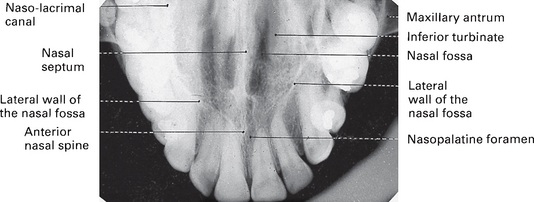
Upper oblique occlusal
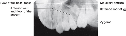
This projection shows the posterior part of the maxilla and the upper posterior teeth on one side.
Main clinical indications
• Periapical assessment of the upper posterior teeth, especially in adults unable to tolerate periapical image receptor holders
• Evaluation of the size and extent of lesions such as cysts, tumours or other bone lesions affecting the posterior maxilla
• Assessment of the condition of the antral floor
• As an aid to determining the position of roots displaced inadvertently into the antrum during attempted extraction of upper posterior teeth
• Assessment of fractures of the posterior teeth and associated alveolar bone including the tuberosity.
Technique and positioning
1. The patient is seated with the head supported and with the occlusal plane horizontal and parallel to the floor.
2. The image receptor, suitably barrier wrapped, is inserted into the mouth on to the occlusal surfaces of the lower teeth, with its long axis anteroposteriorly. It is placed to the side of the mouth under investigation, and the patient is asked to bite together gently.
3. The X-ray tubehead is positioned to the side of the patient’s face, aiming downwards through the cheek at an angle of 65°–70° to the image receptor, centring on the region of interest (see Fig. 12.3).
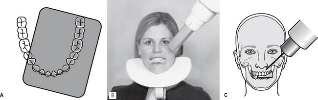
Fig. 12.3 A Diagram showing the position of the image receptor in relation to the lower arch for a LEFT upper oblique occlusal. B Positioning for the LEFT upper oblique occlusal from the front; note the use of the protective thyroid shield. C Diagram showing the positioning from the front.
Note: If the X-ray tubehead is positioned too far posteriorly, the shadow cast by the body of the zygoma will obscure the posterior teeth.
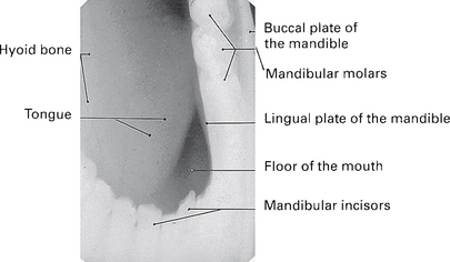
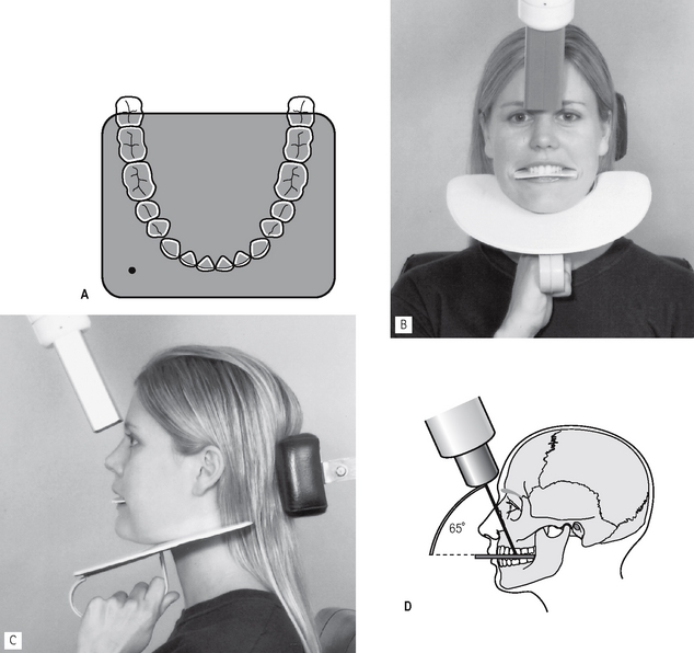
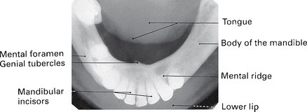
Lower 90° occlusal
This projection shows a plan view of the tooth-bearing portion of the mandible and the floor of the mouth. A minor variation of the technique is also used to show unilateral lesions.
Main clinical indications
• Detection of the presence and position of radiopaque calculi in the submandibular salivary ducts
• Assessment of the bucco-lingual position of unerupted mandibular teeth
• Evaluation of the bucco-lingual expansion of the body of the mandible by cysts, tumours or other bone lesions
• Assessment of displacement fractures of the anterior body of the mandible in the horizontal plane.
Technique and positioning
1. The image receptor, suitably barrier wrapped and facing downwards, is placed centrally into the mouth, on to the occlusal surfaces of the lower teeth, with its long axis crossways. The patient is asked to bite together gently.
2. The patient then leans forwards and then tips the head backwards as far as is comfortable, where it is supported.
3. The X-ray tubehead, with circular collimator fitted, is placed below the patient’s chin, in the midline, centring on an imaginary line joining the first molars, at an angle of 90° to the image receptor (see Fig. 12.5).
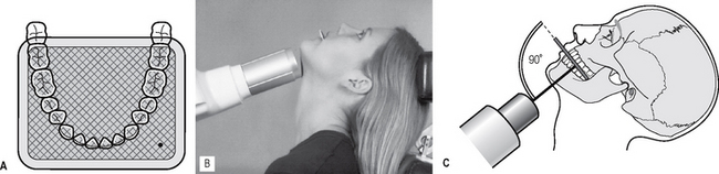
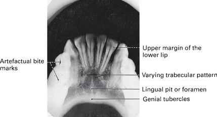
Fig. 12.5 A Diagram showing the position of the image receptor (facing downwards) in relation to the lower arch. B Positioning for the lower 90° occlusal from the side. C Diagram showing the positioning from the side.
Variation of technique.
To show a particular part of the mandible, the image receptor is placed in the mouth with its long axis anteroposteriorly over the area of interest. The X-ray tubehead, still aimed at 90° to the film, is centred below the body of the mandible in that area.
Note: The lower 90° occlusal is mounted as if the examiner were looking into the patient’s mouth. The radiographic film is therefore mounted with the embossed dot pointing away from the examiner.
Lower 45° (or anterior) occlusal
This projection is taken to show the lower anterior teeth and the anterior part of the mandible. The resultant radiograph resembles a large bisected angle technique periapical of this region.
Main clinical indication
• Periapical assessment of the lower incisor teeth, especially useful in adults and children unable to tolerate periapical image receptor holders
• Evaluation of the size and extent of lesions such as cysts or tumours affecting the anterior part of the mandible
• Assessment of displacement fractures of the anterior mandible in the vertical plane.
Technique and positioning
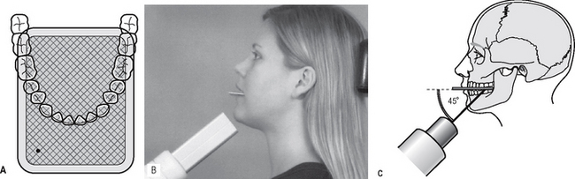
1. The patient is seated with the head supported and with the occlusal plane horizontal and parallel to the floor.
2. The image receptor, suitably barrier wrapped and facing downwards, is placed centrally into the mouth, on to the occlusal surfaces of the lower teeth, with its long axis anteroposteriorly, and the patient is asked to bite gently together.
3. The X-ray tubehead is positioned in the midline, centring through the chin point, at an angle of 45° to the image receptor (see Fig. 12.7).
Lower oblique occlusal
This projection is designed to allow the image of the submandibular salivary gland, on the side of interest, to be projected on to the film. However, because the X-ray beam is oblique, all the anatomical tissues shown are distorted.
Technique and positioning
1. The image receptor, suitably barrier wrapped, and facing downwards, is inserted into the mouth, on to the occlusal surfaces of the lower teeth, over to the side under investigation, with its long axis anteroposteriorly. The patient is asked to bite together gently.
2. The patient’s head is supported, then rotated away from the side under investigation and the chin is raised. This rotated positioning allows the subsequent positioning of the X-ray tubehead.
3. The X-ray tubehead with circular collimator is aimed upwards and forwards towards the image receptor, from below and behind the angle of the mandible and parallel to the lingual surface of the mandible (see Fig. 12.9).
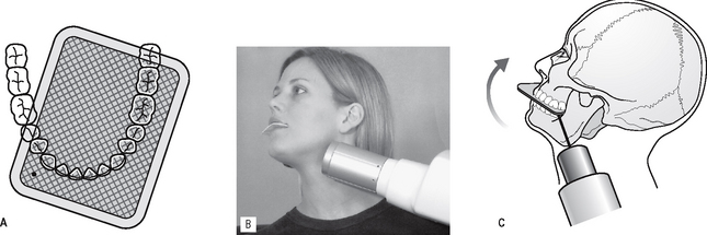
Fig. 12.9 A Diagram showing the position of the image receptor (facing downwards) in relation to the lower arch for the LEFT lower oblique occlusal. B Positioning for the LEFT lower oblique occlusal from the side. C Diagram showing the positioning from the side and indicating that the patient’s chin is raised and that the head is rotated AWAY from the side under investigation.
Note: The lower oblique occlusal radiographic film is also mounted with the embossed dot pointing away from the examiner.