Chapter 25 Developmental abnormalities
INTRODUCTION
There are many developmental abnormalities that can affect the teeth and facial skeleton. In most cases, clinicians need little more than to be able to recognize these abnormalities — this recognition being based on both the clinical and radiographic findings. Therefore, the bulk of this chapter is designed like an atlas to show examples of some of the more common and important abnormalities that have characteristic radiographic features. A broad classification of the main conditions is also included.
Two important developmental anomalies are often encountered: unerupted mandibular wisdom teeth and malpositioned maxillary canines. These two topics are described in more detail.
CLASSIFICATION OF DEVELOPMENTAL ABNORMALITIES
Developmental anomalies of the maxillofacial region are usually classified into:
Anomalies of the teeth
These include abnormalities in:
Abnormalities in structure
Abnormalities in shape
Anomalies affecting whole teeth
• Fusion — two teeth joined together from the fusion of adjacent tooth germs
• Gemination — two teeth joined together but arising from a single tooth germ
• Concrescence — two teeth joined together by cementum
• Dens-in-dente (invaginated odontome) — infolding of the outer surface of a tooth into the interior usually in the cingulum pit region of maxillary lateral incisors.
Anomalies affecting roots and / or pulp canals
• Number — additional roots, e.g. two-rooted incisors, three-rooted premolars or four-rooted molars
• Pulp stones — localized or associated with specific syndromes, e.g. Ehlers–Danlos (floppy joint syndrome)
• Cementoma (see odontogenic tumours in Ch. 28).
Abnormalities in position
Other positional anomalies
• Transposition, two teeth occupying exchanged positions
• Wandering teeth, movement of unerupted teeth for no apparent reason (distal drift)
• Submersion, second deciduous molars apparently descend into the jaws. Since these teeth do not in fact submerge, but rather remain in their original position while the adjacent alveolar bone grows normally, they are now described as being infraocclusal.
TYPICAL RADIOGRAPHIC APPEARANCES OF THE MORE COMMON AND IMPORTANT DEVELOPMENTAL ABNORMALITIES
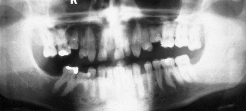
Fig. 25.1 Dental panoramic radiograph showing hypodontia.  are congenitally missing and
  is rudimentary and peg-shaped.
 .
.
 .
.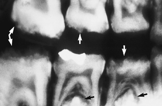
Fig. 25.4 Right bitewing showing the enamel defects of amelogenesis imperfecta (arrowed) in both the deciduous and permanent dentitions.
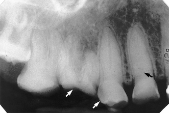
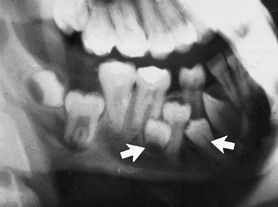
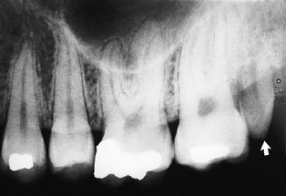
Fig. 25.5 Periapical of maxillary premolars and molars showing the defects of dentinogenesis imperfecta. Note the near obliteration of the pulp chamber (black arrow) and loss of the overlying enamel (white arrows).
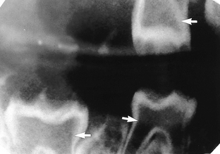
Fig. 25.6 Bitewing showing so-called shell teeth — a type of dentinogenesis imperfecta. The enamel is essentially normal but there is almost no dentine and the pulp chambers are very large (arrowed).
 (arrowed).
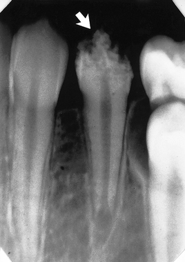
Fig. 25.8 Periapical of  showing the typical gnarled enamel defects of a Turner tooth (arrowed), caused by previous infection of the deciduous predecessor.
 (arrowed).
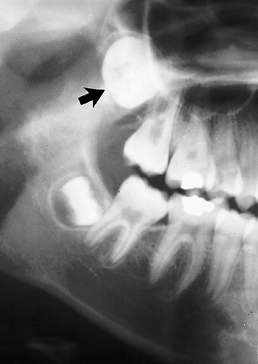
 (arrowed).
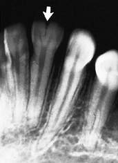
 (arrowed).
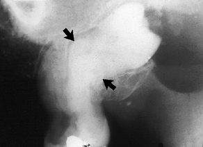
Fig. 25.12 Periapical suggesting concrescence of  (arrowed). Note it is not possible to be certain simply from the radiograph that
  are joined together with cementum.
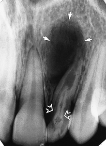
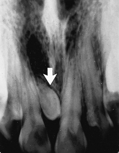
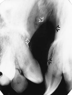
Fig. 25.13 Periapical showing a dens-in-dente or invaginated odontome involving  (open arrows). There is an associated periapical area of infection (solid arrows) — a common occurrence with dens-in-dente.
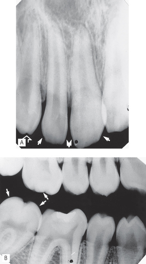
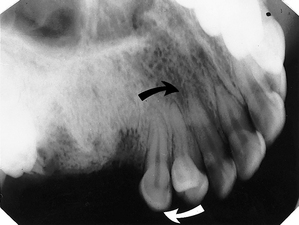
Fig. 25.14 Congenital syphilis. A Periapical of maxillary incisors and canine showing Hutchinson’s teeth. Note the tapering screwdriver-shaped crowns (solid arrows) and the incisal edge notching (open arrow). B Bitewing showing Moon’s/mulberry molars. Note the dome-shaped, nodular appearance of the molars (arrowed).
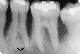
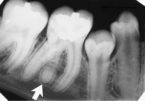
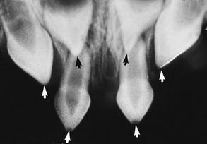
Fig. 25.17 Periapical showing the typical tapering pointed incisor teeth (arrowed) of ectodermal dysplasia.
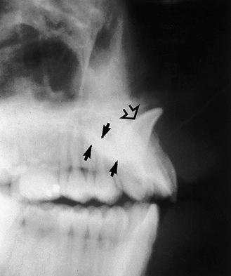
Fig. 25.18 Lateral view showing a dilacerated  . The crown (open arrow) and the root (solid arrows) are in different planes as a result of the near right angle bend in the root.
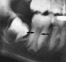
Fig. 25.19 Part of a panoramic radiograph showing a taurodont lower second molar with the typical large pulp chamber (arrowed).
 .
.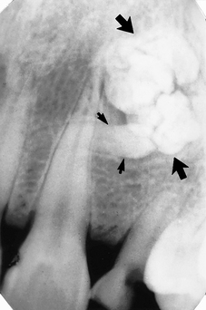
Fig. 25.21 Periapical showing a compound odontome in the anterior maxilla — several small discrete denticles are evident (arrowed) (right).
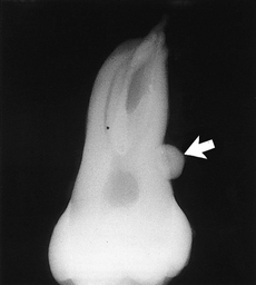
Fig. 25.22 Extracted upper second molar with an almost spherical enameloma (enamel pearl) on its distal aspect (arrowed).
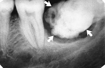
Fig. 25.23 Periapical showing a complex odontome, a disorganized mass of dental tissues in  region (arrowed).
 to give
  (arrowed).
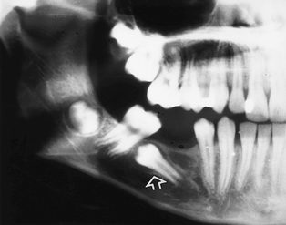
 (arrowed).
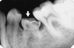
Fig. 25.26 Periapical showing a submerging or infra-occlusal  (arrowed). Note there is no underlying second premolar.
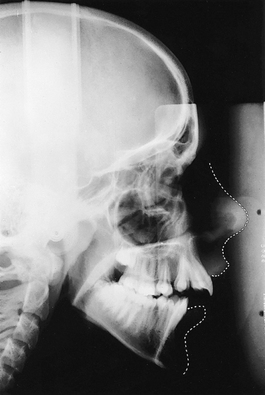
Fig. 25.27 True cephalometric lateral skull showing micrognathia (underdeveloped mandible) in skeletal Class II. The soft tissue profile has been drawn in.
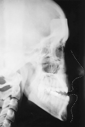
Fig. 25.28 True cephalometric lateral skull showing macrognathia (overgrowth of the mandible) in skeletal Class III. The soft tissue profile has been drawn in.
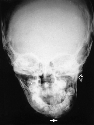
Fig. 25.29 PA skull showing condylar hypoplasia on the left side (open arrow), with a marked deviation of the midline of the mandible to that side (closed arrow).
 is absent.
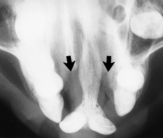
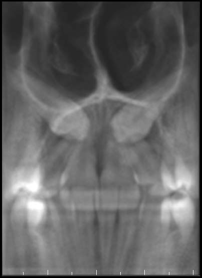
Fig. 25.32 Upper standard occlusal showing a bilateral cleft palate (arrowed). Both lateral incisors are absent.
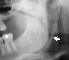
Fig. 25.33 Part of a panoramic radiograph showing a long calcified stylo-hypoid ligament (arrowed), a feature of Eagle’s syndrome.
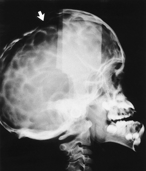
Fig. 25.34 True cephalometic lateral skull showing the typical copper beaten appearance of the cranium resulting from craniosynostosis — premature fusion of the cranial sutures. This appearance is seen in both Crouzon’s and Apert’s syndromes. In this patient, there is also indentation of the anterior fontanelle (arrowed) and the maxilla is hypoplastic.
RADIOGRAPHIC ASSESSMENT OF MANDIBULAR THIRD MOLARS
Clinical symptoms associated with lower wisdom teeth are common, the usual treatment being extraction. Many of the factors that influence that decision and determine the difficulty of the extraction are revealed by the preoperative radiographic assessment.
Radiographic views used
The usual radiographs used include:
Periapicals need to be of good quality. In particular, the geometric relationship of the third molar to the surrounding structures must be accurate. To satisfy this requirement, modifications to conventional radiographic techniques are often necessary, as described in detail in Chapter 10. If available, cone beam CT, described in Chapter 19, can greatly facilitate this radiographic assessment by providing images in the coronal, axial and sagittal planes.
Radiographic interpretation
The specific features that need to be identified can be divided into those related to:
Lower third molar assessment
The main features to examine include:
• The relationship of the apices with the inferior dental (ID) canal
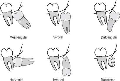
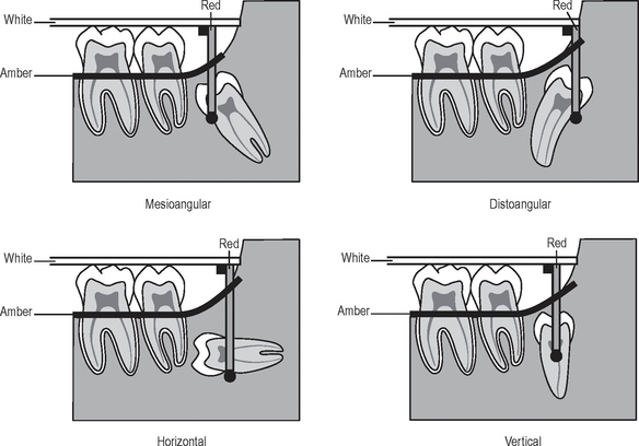
Angulation (see Fig. 25.35)
The relationship of the apices to the ID canal
The apices of the lower third molar often appear close to the ID canal. This apparent closeness is usually due to these structures being superimposed. However, an intimate relationship does sometimes exist. The root may be grooved by the canal, or rarely, included within the developing root, as illustrated in Figure 25.37.
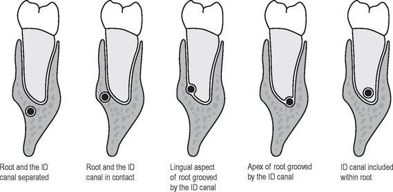
Fig. 25.37 Diagrams illustrating the types of intimate relationships that can exist between the lower third molar root and the inferior dental canal.
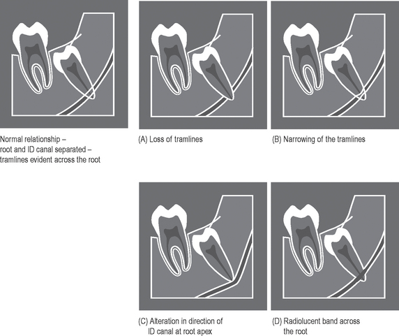
The normal radiographic appearance of the ID canal (two thin, parallel radiopaque lines — the so-called tramlines) and the variations that indicate a possible intimate relationship are shown in Figure 25.38. These variations include:
The depth of the tooth in the alveolar bone
Two main methods are used commonly to assess tooth depth:
Winter’s lines (see Fig. 25.39).
In this method, three imaginary lines (traditionally described by number or colour) are drawn on a geometrically accurate periapical radiograph, as follows:
• The first or white line is drawn along the occlusal surfaces of the erupted first and second molars.
• The second or amber line is drawn along the crest of the interdental bone between the first and second molars, extending distally along the internal oblique ridge, NOT the external oblique ridge. This line indicates the margin of the alveolar bone surrounding the tooth.
• The third or red line is a perpendicular dropped from the white line to the point of application for an elevator, but is measured from the amber line to this point of application. This line measures the depth of the third molar within the mandible. (As a general rule, if the red line is 5mm or more in length, the extraction is considered sufficiently difficult for the tooth to be removed under general anaesthetic or using local anaesthetic and sedation.)
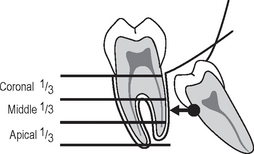
Using the roots of the second molar as a guide (see Fig. 25.40)
This method can be summarized as follows:
• The roots of the adjacent second molar are divided horizontally into thirds
• A horizontal line is then drawn from the point of application for an elevator to the second molar
• If the point of application lies opposite the coronal, middle or apical third, the extraction is assessed as being easy, moderate or difficult, respectively.
The buccal or lingual obliquity
• Buccal obliquity — the crown of the wisdom tooth is inclined towards the cheek
• Lingual obliquity — the crown of the wisdom tooth is inclined towards the tongue.
The lie of the tooth in the horizontal plane cannot be determined accurately from a periapical radiograph. The views of choice for this assessment include:
• Lower 90° occlusal, centred on the side of interest (see Ch. 12).
Lower second molar assessment
The second molar is assessed to decide the prognosis of the tooth to decide whether the second molar should be extracted instead of, or as well as, the third molar. The main features to examine include:
Assessment of the surrounding bone
The main features to examine include:
• The anteroposterior position of the ascending ramus, to determine access to the tooth and the amount of overlying bone
All these points relating to the third molar, the second molar and the surrounding tissues are considered together, and a conclusion drawn as to the overall difficulty of the proposed extraction.
Examples of unerupted lower third molars, illustrating some of the more important radiographic features, are shown in Figures 25.41-25.47.
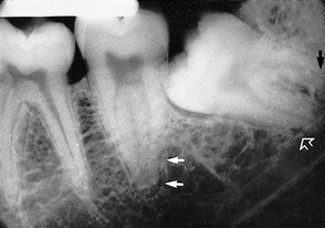
Fig. 25.41 Mesioangularly impacted  . Note the unfavourable root curvatures (black arrow), the uninterrupted upper tramline of the inferior dental canal (open white arrow) and the conically shaped root of
  (solid white arrows).
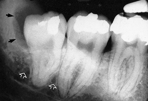
Fig. 25.42 Slightly distoangularly impacted  . Note the favourable conically shaped roots, the uninterrupted upper tramline of the inferior dental canal (open white arrows) and the radiolucent area distal to the crown (black arrows) caused by the residual follicle.
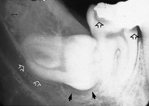
Fig. 25.43 Horizontally impacted  . Note the pincer-shaped roots and their indentation of the upper margin of the inferior dental canal (open white arrows), radiolucency beneath the crown (solid black arrows) caused by the follicle. In addition, note the carious lesions in
  (open black arrows).
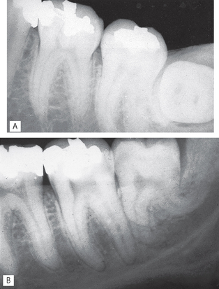
Fig. 25.44 Transversely positioned  . The crown is viewed end-on. Note that the bucco/lingual obliquity of the tooth cannot be determined from this radiograph. B Vertically positioned
  with very unfavourable root curvatures.
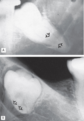
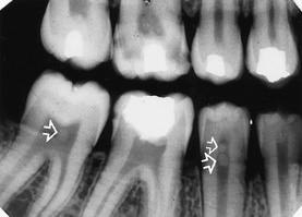
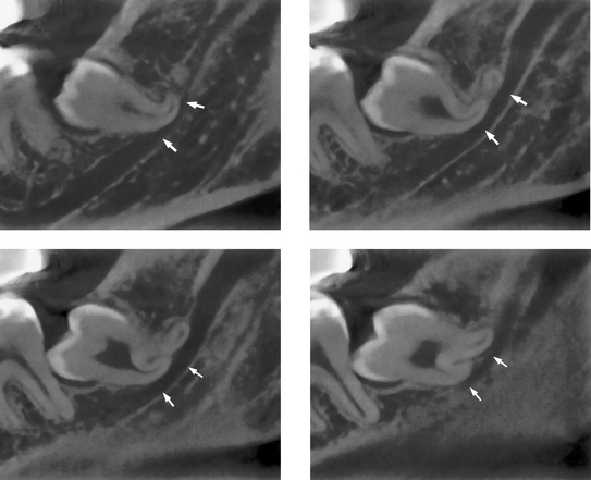
Fig. 25.45 Two radiographs showing some of the radiographic features suggestive of an intimate relationship with the inferior dental canal. A A radiolucent band is evident across the root (arrowed) and there is a change in direction of the ID canal. B A radiolucent band evident across the root and the ID canal is narrowed (arrowed).
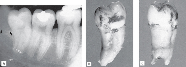
Fig. 25.46 A Slightly distoangularly impacted  . Note the extensive area of bone resorption distal to the crown (black arrows) caused by previous pericoronal infection. There is a radiolucent band across the tooth apex which is also hazy in outline (open white arrows) caused by the inferior dental canal, implying an intimate relationship. B The extracted
  viewed as in the radiograph from the buccal aspect. C The extracted tooth viewed from the distal aspect showing clearly the notching of the tooth apex by the inferior dental canal. This explains the radiolucent band across the apex — there is simply less tooth tissue in this zone, because of the position of the inferior dental canal.
(Specimen and radiograph kindly supplied by Dr A. Sidi.)
 showing the relationship of the roots to the ID canal
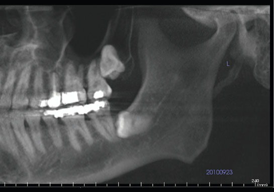
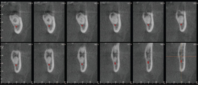
 , A panoramic lateral view and B a series of cross-sectional images through the wisdom tooth showing the position of the ID canal clearly.
RADIOGRAPHIC ASSESSMENT OF UNERUPTED MAXILLARY CANINES
The upper canines are often misplaced and fail to erupt as a result of their long path of eruption, the timing of their eruption and the frequency of upper arch overcrowding. Again, many of the factors that influence the treatment of this anomaly can be obtained from the radiographic assessment, the purpose of which is two-fold:
• To determine the size and shape of the canine and any related disease including possible resorption of the adjacent lateral incisor.
Assessment of the canine size and shape and the surrounding tissues
Radiographic views used (see Fig. 25.49)
The usual radiographs used include:
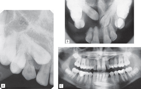
Fig. 25.49 Examples of the radiographs used typically to assess unerupted canines and the surrounding structures.
A Periapical showing unerupted  wih retained C.
B Upper standard occlusal showing both upper canines unerupted, a dentigerous cyst associated with  , extensive destruction of the alveolar bone and resorption of
  .
.
 .
.Assessment of the position of the canine — localization
There are several methods available for localization depending on available facilities. They can be used for canines and other unerupted teeth as well as odontomes and supernumeraries. Although emphasis in this section is on canines, examples of localization of other unerupted developmental anomalies are also shown.
The principle of parallax
Parallax is defined as the apparent displacement of an object because of different positions of the observer. In other words, if two objects, in two separate planes, are viewed from two different positions, the objects will appear to move in different directions in relation to one another, from one view to the next, as shown in Figure 25.50.
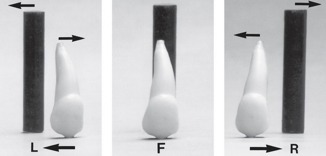
Fig. 25.50 The principle of parallax. Photographs of a small black cylinder positioned behind a tooth. From directly in front (F), the tooth and cylinder are superimposed. With the camera moved to the left (L), the tooth and cylinder are both visible and appear to have moved in different directions. The cylinder, being further away from the camera, appears to have moved in the same direction as the camera, i.e. to the left, while the tooth appears to have moved in the opposite direction. With the camera moved to the right (R) a similar apparent movement of the tooth and cylinder relative to the camera takes place, with the cylinder appearing to have moved to the right and the tooth to the left.
Using the principle of parallax, if two views of an unerupted canine are taken with the X-ray tubehead in two different positions, the resultant radiographs will show a difference in the position of the unerupted canine relative to the incisors, as follows:
• If the canine is palatally positioned, it will appear to have moved in the same direction as the X-ray tubehead.
• If the canine is buccally positioned, it will appear to have moved in the opposite direction to the X-ray tubehead.
• If the unerupted canine is in the same plane as the incisors, i.e. in the line of the arch, it will appear not to have moved at all.
A useful acronym to remember the movements of parallax is SLOB, standing for:
Parallax in the horizontal plane
The movement of the X-ray tubehead is in the horizontal plane, for example:
• 2 periapicals — one centred on the upper central incisor and the other centred on the canine region, as shown in Figure 25.51.
• An upper standard occlusal, centred in the midline plus a periapical or an upper oblique occlusal, centred on the canine region.
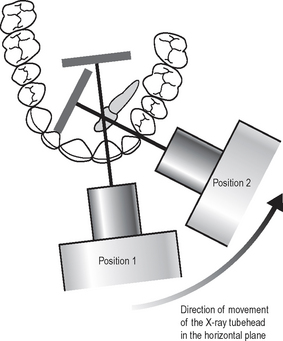
Fig. 25.51 Diagram showing the two different tubehead positions required for parallax in the horizontal plane: Position (1) centred on the upper central incisor. Position (2) centred on the canine region.
Examples are shown in Figures 25.52-25.54.
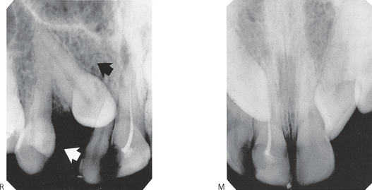
Fig. 25.52 Two periapicals showing the relative positions of the unerupted  to the incisors — M in the midline and R from the right. The X-ray tubehead (white arrow) and the canine (black arrow) appear to have moved in the same direction. The canine is thus palatally positioned.
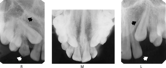
Fig. 25.53 (right) An upper standard occlusal (the mid-line view) and two periapicals centred on the unerupted canines on either side. The teeth can be localized as follows:
1. Examine the midline view radiograph (M), centred on the upper central incisors. The tip of the RIGHT canine appears opposite the root canal of  ; the tip of the LEFT canine appears opposite the mesial aspect
  .
.
2. Examine radiograph (R), the periapical centred on the RIGHT canine region (i.e. the X-ray tubehead has been moved distally in the direction of the white arrow). The tip of the canine appears opposite the mesial aspect of  . Therefore, it appears to have moved distally in the direction of the black arrow, i.e. in the same direction as the X-ray tubehead was moved.
3. Examine radiograph (L), the periapical centred on the LEFT canine region. The tip of the canine appears opposite the root canal of  . Again both the X-ray tubehead (white arrow) and the canine (black arrow) appear to have moved in the same direction.
Thus the crowns of both the right and left canines are palatally positioned in relation to the incisors.
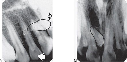
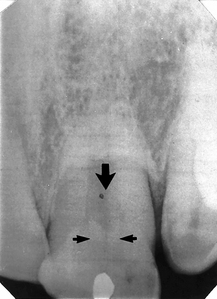
Fig. 25.54 Two periapicals showing an unerupted mesiodens. It can be localized as follows:
1. Examine the mid-line radiograph (M). The tip of the mesiodens’ crown appears opposite the mesial aspect of  , while its apex appears opposite the root canal of
  .
.
2. Examine the periapical centred on the RIGHT canine region (R). The tip of the mesiodens crown appears opposite the root canal of  , while its apex appears opposite the mesial aspect of
  .
.
3. The X-ray tubehead was moved distally in the direction of the large white solid arrow.
4. The crown of the mesiodens appears to have moved mesially (black open arrow), i.e. in the opposite direction to the tubehead. It is thus buccally placed.
5. The apex appears to have moved in the same direction (white open arrow) as the tubehead and is thus palatally placed.
The mesiodens thus lies across the arch, between the central incisors, with its crown buccally positioned and its apex palatally positioned.
Note: The advantage of the upper standard occlusal for the initial view is that it shows both sides of the arch and unerupted canines are often bilateral.
Parallax in the vertical plane
The movement of the X-ray tubehead is in the vertical plane, for example:
• A dental panoramic radiograph — the X-ray beam is aimed upwards at 8° to the horizontal
• An upper standard occlusal — the X-ray beam is aimed downwards at 65°–70° to the horizontal, as shown in Figures 25.55 and 25.56.
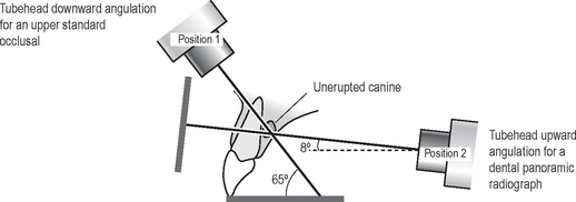
Fig. 25.55 Diagram showing the two different tubehead positions when taking a dental panoramic radiograph and an upper standard occlusal, allowing parallax in the vertical plane.
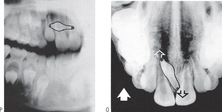
Fig. 25.56 Part of a dental panoramic radiograph and an upper standard occlusal showing an unerupted mesiodens. It can be localized as follows:
1. Examine the panoramic radiograph (P) taken with the tubehead aimed upwards at 8° to the horizontal. The tip of mesiodens’ crown appears opposite the neck of the lateral incisor, while its apex appears opposite the root of  .
.
2. Examine the occlusal radiograph (O) taken with the tubehead aimed downwards at 65° to the horizontal. The tip of the mesiodens’ crown now appears beyond the apex of  , while its apex appears opposite the crown of
  .
.
3. The X-ray tubehead has moved vertically upwards from view (P) to view (O) in the direction of the solid white arrow.
4. The crown of the mesiodens appears to have moved in the same direction (white open arrow) and is thus palatally placed.
5. The apex of the mesiodens appears to have moved in the opposite direction (black open arrow), and is thus buccally placed.
The mesiodens thus lies across the arch between the central incisors, with its crown palatally positioned and its apex buccally positioned.
Note: This combination of views is used frequently in orthodontics, when patients with unerupted canines are usually assessed. Use of these films to their full potential may obviate the need for further films merely to localize the unerupted canines.
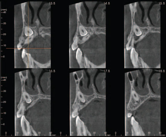
Localization using cross-sectional spiral tomography and cone beam CT
Localization of unerupted developmental anomalies using these more modern advanced imaging modalities is straightforward (see Ch 17 and 19), if the facilities are available. They allow visualization of the unerupted abnormality in different planes. There is no need to use the principles of parallax. Two examples are shown in Figures 25.57 and 25.58.
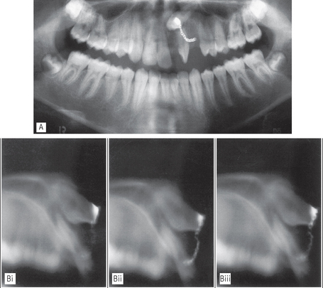
Fig. 25.57 Scanora® images. A Panoramic radiograph and B three 2 mm cross-sectional spiral tomographs showing the relative positions of bucally placed unerupted left canine (with orthodontic chain attached) and the left lateral incisor. The two teeth are clearly separated and there is no evidence of root resorption of the lateral incisor.