22 Full-arch fixed prosthesis
‘All-on-4™’/‘All-on-6’ approach
Introduction
The conventional full-arch fixed implant-supported prosthesis often needs placement of several implants (8–12) to support a 12- to 14-unit fixed prosthesis. Moreover, the patients who come to the implant dentist for the full-arch implant-supported prosthesis usually present the loss of ridge volume especially in the maxillary and mandibular posterior regions, which limits the insertion of the implant with adequate dimensions without prior bone augmentation. The long-term edentulism of the posterior maxilla or replacement of lost maxillary molars and premolars other than the implant prosthesis, may result in lowering of the sinus floor because of the pneumatization of the sinus. In several cases, it results in the presence of inadequate subantral bone height to insert the implant. Thus, in several cases that need the full-arch implant prosthesis, the sinus augmentation procedure needs to be performed to regenerate the desired bone dimensions. However, this procedure may take 6–8 months before implants can be inserted. Moreover, the density of the bone in this region is usually poor and may require subgingival healing of the inserted implants for a further 6–8 months before they are loaded to support fixed prostheses.
So restoring the maxilla with fixed full-arch implant-supported prosthesis offers several disadvantages such as the need for sinus grafting procedures in some cases, delayed implant placement, a long time span (6 months to 1 year) to restore the case, multiple surgical interventions, more complications, a long period of wearing a provisional prosthesis (usually removable), high cost of the procedure, etc.
Similarly, the full-arch implant-supported mandibular prosthesis needs the insertion of 6–10 implants. The presence of mental foramina limits long implant placement only in the anterior mandibular region and often the bone available above the mandibular canals in the posterior mandible is found inadequate for the insertion of an adequately long implant. This results in the possibility of the placement of only 5–6 implants in the mandibular anterior region and a fixed prosthesis with long distal cantilevered extensions, which can be placed to a limited extent to avoid future complications. The onlay grafting to generate bone volume in the posterior mandible needs a lot of surgical interventions, a long time span to complete treatment, more complications, increased cost, etc.
To overcome these problems and to restore the full-arch cases immediately after graftless implant insertion, Dr Paulo Malo at the Malo Clinic, Lisbon, Portugal invented the ‘All-on-4™’ implant procedure. In 1993, he performed the pilot study to establish the All-on-4™ standard protocol. Since 1998, when the NobelSpeedy implant (Nobel Biocare, India) was developed, he published many retrospective studies about All-on-4™ for maxillary and mandibular rehabilitation.
All-on-4™ is a graftless implant placement procedure for restoring the edentulous jaw by tilting posterior implants for utilizing maximum amount of bone and stabilizing them in highest possible bone density. The tilting of posterior implants reduces the length of posterior cantilevering of the prosthesis. Moreover, it allows long implant placement and the insertion of the implant apex in the high-density anterior maxilla or anterior mandible, to achieve adequate primary stability for immediate loading on the implants, using a provisional splinted acrylic prosthesis. Hence, this facilitates optimal support for an acrylic prosthesis that can be immediately fixed over the inserted implants to restore aesthetics and function within a few hours of implant insertion surgery. All-on-4™ is based on Nobel Biocare’s pioneering ‘Immediate Function’ capability.
To perform this technique, a total of four implants are inserted with the back implants tilted up to 45°, often in close approximation to the inferior and anterior wall of maxillary sinus in the upper jaw and superior and anterior to the inferior alveolar nerve and mental foramina in the mandible, to take maximum advantage of existing bone by inserting long implants and firmly stabilizing their apex in high-density anterior bone. A fixed standardized surgical guide is used to correct implant placement. Both flap and flapless (guided) approaches are compatible with the technique. Special components are developed to correct the prosthetic angulation of the tilted implants as well as to immediately restore the implants in function. If necessary, a cantilever can also be added to the final prosthesis. The skilled approach of tilting the posterior implants avoids expensive, time-consuming, and more invasive grafting procedures like sinus grafting, block grafting, etc.
Step by step diagrammatic presentation of All-on-4™ in the mandible is shown in Fig 22.1A–E.
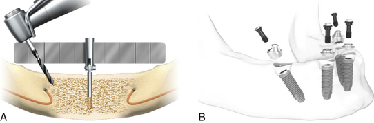
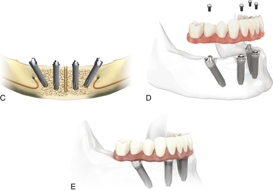
Fig 22.1 Flaps are elevated to expose the bony ridge, and the mental foramina are located. An osteotomy of approximately 10 mm depth in the midline is prepared using a ϕ 2 mm twist drill and the All-on-4 guide is correctly placed in this midline osteotomy. The posterior osteotomies are prepared to the appropriate depth and tilted distally to the maximum angle of 45°. (A) The posterior osteotomies are prepared in such a manner that the posteriorily tilted implants are placed minimum 2 mm anterior to the inferior alveolar nerve. The osteotomies for the anterior implants are prepared in the usual manner. (B and C) After placing all the four implants, the straight or 17° multiunit abutments are placed on top of the anterior implants whereas the 30° multiunit abutments are inserted over the posterior tilted implants. Multiunit abutments of appropriate collar height should be selected for each implant and should be tightened to 15 Ncm using torque ratchet. (D and E) Immediate provisional and later on definitive hybrid prosthesis are fixed over these implants using fixation screws.
(Courtesy: Nobel Biocare, India).
Step by step diagrammatic presentation of All-on-4™ in the maxilla is shown in Fig 22.2A–D
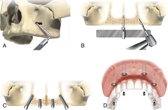
Fig 22.2 Flap is elevated to expose the bony ridge as well as lateral wall of the maxillary sinus. A small opening on the lateral wall of the sinus is prepared where the anterior wall of the sinus is expected. Further, the anterior wall of the maxillary sinus is explored by using a probe through this opening. (A) The lateral window is extended if necessary and position of the anterior wall is marked using a sterile pencil. An osteotomy approximately 10 mm depth is prepared in the midline using a ϕ 2 mm twist drill and the All-on-4™ guide is correctly placed in the midline osteotomy. (B) The osteotomies for the posterior implants should be started as posterior as possible to minimize the cantilever and allowing approximately 4 mm distance from the sinus. The posterior osteotomies are prepared to the appropriate depth and tilted to the maximum angle to the 45°, so that the posteriorly tilted implants are placed a minimum 2 mm anterior to the anterior wall of the sinus. Two implants at the most-anterior position are placed in the usual manner. (C) The 17° or straight multiunit abutments are placed on the anterior implants whereas the 30° multiunit abutments are placed on the posterior implants. (D) Immediate provisional and later on definitive hybrid prosthesis are fixed over the implants using fixation screws.
(Courtesy: Nobel Biocare, India)
All-on-6 technique
Because of graftless implant placement and immediate loading, the All-on-4™ technique is very successfully being performed by many dentists and has gained high popularity among implant dentists as well as patients. The only limitation with this technique is that prosthesis with only limited number of teeth (10–12 units) can be fixed over these four implants. Further, the loss of any one implant reverts the entire procedure to the initial stage.
To avoid such problems and also for the patients who express the desire for a 14-unit prosthesis, two more implants can be inserted posterior to the posterior wall of the sinus in the maxillary tuberosity and tilted anteriorly at 45° to minimize the length of the unsupported bridge framework between two distal implants. The severely resorbed posterior maxilla with a large volume of posterior expansion of the sinus often does not leave enough bone volume in the tuberosity region to place an implant of an adequate size. In such cases, the implant is inserted in the tuberosity with the apex of the implant at the junction of the pyramidal process of the palatine bone and the pterygoid process of the sphenoid bone. The implant placed would then engage all three bone segments that constitute this region. The implant placement in the tuberosity with its apex engaging the medial pterygoid process of sphenoid bone is the most preferred option because it allows the multicortical engagement of the implant to achieve adequate initial stability for the implant.
To perform the All-on-6 procedure in the mandible, the two straight implants should be inserted usually at the first or second molar site but if inadequate ridge height above the mandibular canal does not allow placement of implants in the molar region, then the short and wide implant can be inserted at the angle of the mandible (into the buccal shelf area) tilted anteriorly at 30–45°.
With the few advantages, there are also several disadvantages with All-on-6 procedures such as increased cost, need of a highly skilled approach to correctly place implants in pterygoid process, difficult approach for the insertion and restoration of posterior implants, need of a skilled technician to fabricate the prosthesis, and problems in oral hygiene maintenance in the back region.
Comparative features of the traditional versus All-on-4™/All-on-6 approach
Advantages of the All-on-4™/All-on-6 technique
1. Vast numbers of the edentulous patients can be treated with the technique.
2. Being a graftless and immediate loading technique, it is more acceptable to patients.
3. Fewer implants are inserted.
4. Fixed teeth can be given on four implants to patients for whom sinus grafting/nerve transpositioning procedures are contraindicated.
Table 22.1 Comparison of the graftless All-on-4™/All-on-6 approaches with the conventional full-arch implant procedure
| COMPARATIVE FEATURE | TRADITIONAL APPROACH FOR RESTORING FULL-ARCH | ALL-ON-4™/ALL-ON-6 APPROACH |
|---|---|---|
| Sinus grafting | May be required | Not required |
| Only grafting | May be required | Not required |
| No. of implants | More no. of implants are inserted | Less no. of implants are needed |
| Immediate fixed restoration in function | May not be possible | Possible |
| Surgery | More invasive | Less invasive |
| Surgical steps | May require multiple surgical steps like grafting procedures, implants insertion, uncovery, etc. | Only one surgical step, i.e. implant insertion |
| Time span needed to deliver the final prosthesis | May take 6 months to 1 year | Can be completed in a few weeks |
| Sinus pathology contraindicating the grafting and implant placement | May not be possible | Possible |
| Patient’s acceptance | Less | More |
| CT guided implant placement | Possible in selective cases | Possible in most cases |
5. Lower cost of the treatment compared to the traditional implant-supported full-arch fixed prosthesis which often needs bone grafting, more implants, multiple surgical steps, etc.
6. Long tilted distal implant can be maximally stabilized by utilizing high-density bone of the anterior region. Placement of longer implants, enhancement of the area of interaction between bone and implant, and also primary anchorage.
7. A greater distance between implants, allowing the elimination of cantilevers in the prosthesis, which results in better load distribution.
8. By reducing the number of implants to four, each implant can be placed without interfering with the adjacent implants.
9. The placement of implants in residual bone, avoiding more complex techniques of bone graft and/or sinus lift.
10. Immediate loading is done in most of the cases so that the patient gets at least provisional fixed teeth on the day of implant placement for aesthetics and function.
11. It can be performed by implant surgeons who are not very expert at performing procedures like sinus grafting, block grafting, nerve transpositioning, etc.
12. Only one surgical step is required (no implant uncovery).
13. The high success rate of the procedure (as shown in the various studies).
14. Treatment completed in very short period of time (in a few weeks) whereas the traditional technique may however take years to complete treatment.
Disadvantages of the All-on-4™/All-on-6 technique
1. It cannot be performed in patients presenting with large osseous defects in the anterior region, which needs grafting procedures to regenerate new bone before All-on-4™ implant placement.
2. Extraction of firm, healthy teeth is mandatory, if any are present in the anterior jaw.
3. Reduction of bone crest causes increased soft tissue height which in turn leads to increased pocket depth around the abutment, more chances of bacterial growth, and peri-implantitis.
4. With the All-on-4™, only the 10- to 12-unit prosthesis is delivered over the four implants, and often patients request the addition of more posterior teeth to maximize chewing efficiency and improve the overall maxillofacial prosthesis.
5. Oral hygiene: Maintenance of the hybrid prosthesis is often difficult for some patients and they need regular visits to the dentist for its cleaning.
Indications
1. Edentulous patients who need fixed implant-supported prosthesis – maxillary, mandibular or both.
2. Patients with partial maxillary/mandibular edentulism with only few intact natural teeth in the anterior region.
3. Patients with worn out dentition which needs extraction and replacement of all teeth.
4. Patients with periodontally compromised mobile teeth which need extraction and replacement.
5. Edentulous or partially edentulous patients with very limited subantral bone height in the posterior maxilla.
6. Edentulous or partially edentulous patients with very limited bone height above the mandibular canals in the posterior mandible.
7. Edentulous patients with maxillary sinus pathologies contraindicating the sinus grafting procedure.
8. Patients with adequate volume of healthy bone in the maxillary and mandibular anterior region to place implants.
9. Implant overdenture cases with severe ridge resorption – tilting posterior implants give more support to the denture and prevent soft tissue abrasion and further bone loss in the posterior region.
Contraindications
1. Patients with inadequate bone volume in the maxillary and mandibular anterior region to place implants.
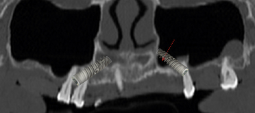
2. Anterior wall of the sinus is located far anterior to the usual position, contraindicating tilting of the posterior implants to reach the second premolar or first molar position (Fig 22.3).
Key points for successful All-on-4™/All-on-6 implant therapy
1. Meticulous treatment planning to see the position and path of anterior, inferior, and posterior wall of maxillary sinus.
2. Dental CT planning if possible, to see the possible placement of the implants with desired dimensions and their three-dimensional positioning for the best possible prosthesis.
3. Placement of longest possible implants and stabilization in the cortical bone such as nasal floor, basal bone of the anterior mandible, pterygoid process, etc. to achieve high primary stability.
4. Tilting of the posterior implants using the All-on-4™ guide to avoid extreme tilting which may result in parallelism problems during restoration.
5. Selection of multiunit abutments with proper collar height and angulation.
6. Sequential radiographs with the drill into the osteotomy during initial osteotomy preparation for posterior implants, to evaluate the direction of the drilling in respect to vital structures such as the sinus wall and the mandibular canal.
7. Placement of the implants with minimum diameter of 3.3mm at the anterior positions and 3.75–4.2mm for the posterior positions to avoid problems such as connection screw loosening and implant body fracture.
8. Adequate vertical ridge reduction before implant placement to avoid the display of the unaesthetic transition line of prosthesis and ridge tissue when the patient smiles (Fig 22.4A–D).
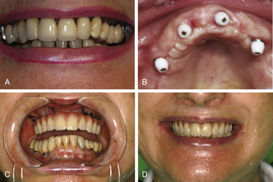
Fig 22.4 (A) Unaesthetic gingival line with the old prosthesis is visible during the smile. A planned vertical ridge reduction before the implant placement results in nonvisibility of the transition line of the final All-on-4™ implant prosthesis, when the patient smiles. (B–D) This gives a natural appearance to the All-on-4™ prosthesis.
(Courtesy: Saad Zemmouri, Morocco).
Management of complications
1. Over or inadequate tilting of the posterior implants. It can be avoided with accurate treatment planning and use of the All-on-4™ guide available from Nobel Biocare.
2. Perforation through the inferior or anterior wall of the sinus. It can be avoided by proper exploration of the anterior wall of the sinus. Pilot drilling should begin a minimum of 4 mm anterior to the sinus, evaluated with a radiograph. If the pilot drill has perforated the sinus cavity, it should be evaluated with a radiograph and the osteotomy preparation should be redirected to the planned direction, avoiding the enlargement of the perforation. The path of the anterior wall of the sinus should be marked on the facial wall using a sterile pencil, so that it can be visualized when drilling for implants.
CASE REPORT-1
Step by step procedure for All-on-6 in the maxilla (Figs 22.5–22.19).
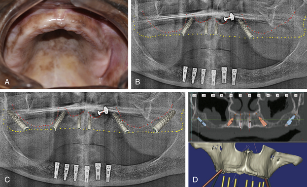
Fig 22.5 (A) Edentulous maxilla. (B) The panoramic radiograph shows adequate bone for All-on-4™ (C) as well as All-on-6 procedure. (D) The dental CT scan shows sinus membrane thickening, contraindicating sinus grafting procedure. Adequate amount of bone is luckily present bilaterally posterior to the sinus to insert adequate size implants, but needs to be laterally condensed to achieve adequate stability for the inserted implants.
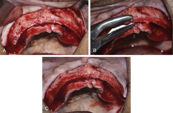
Fig 22.6 (A) Mucoperiosteal flaps are elevated to expose the bone ridge as well as the facial wall of the ridge and (B and C) planned amount of vertical ridge reduction is done using a bone rongeur to achieve the wide ridge crest to place implants with adequate diameters as well as to shift the transition line of the future prosthesis and ridge tissue apical to the high smile line of the patient.
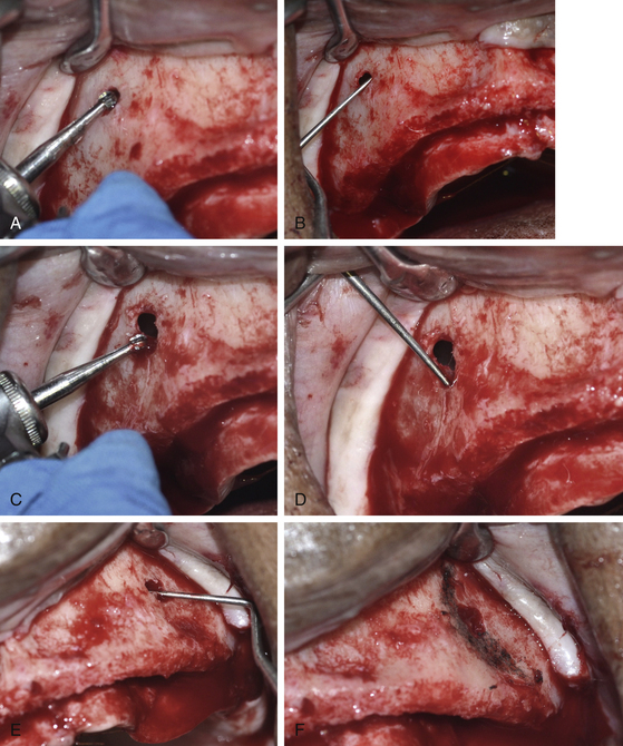
Fig 22.7 (A) A small opening at the lateral wall of the right sinus is prepared using a round carbide bur. (B) The anterior wall of the sinus is explored using a probe. (C) The opening is extended to appropriately explore (D) the complete path of the anterior wall of the sinus. (E) The anterior wall of the left sinus is also explored in the same way and (F) it is marked using a sterile HB pencil.
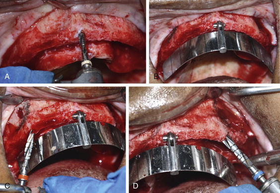
Fig 22.8 (A) An osteotomy is prepared using 2.0 mm pilot drill in the midline and (B) the All-on-4™ guide (Nobel Biocare, India) is placed. (C and D) The osteotomies are prepared for the posterior implants angled at the 45° and just anterior to the anterior wall of the sinus.
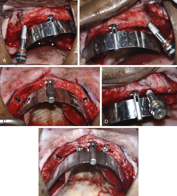
Fig 22.9 (A–C) The posterior implants are installed at the 45° and just anterior to the anterior wall of the sinus. (D and E) Two implants are placed at the anterior positions.
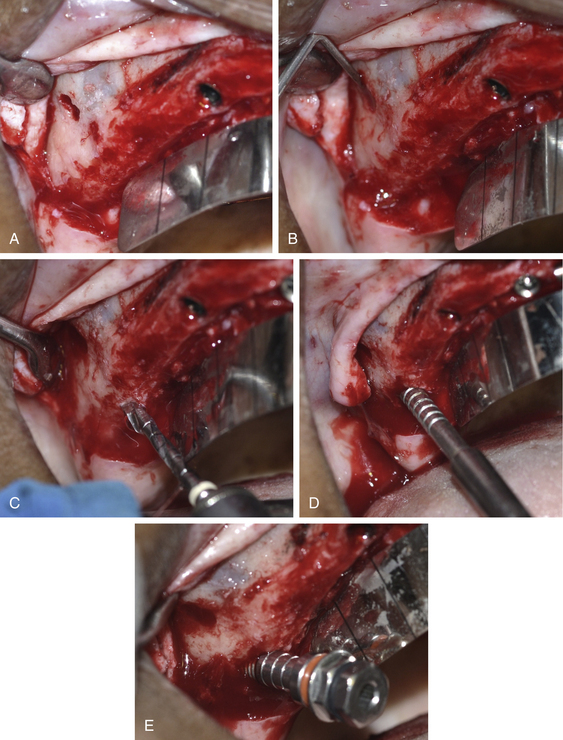
Fig 22.10 (A and B) Posterior wall of the right sinus is explored by preparing another small opening through the lateral wall and (C) the osteotomy is prepared using pilot drill at 45°, just posterior to the posterior wall of the sinus. (D) The osteotomes are then sequentially used for lateral bone condensation to improve the bone density around the implant. (E) The implant which is tilted at 45° is installed.
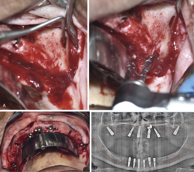
Fig 22.11 (A–C) Posterior wall of the left sinus is also explored in the same fashion and implant is inserted. (D) Postimplantation radiograph shows accurate placement of all six implants.
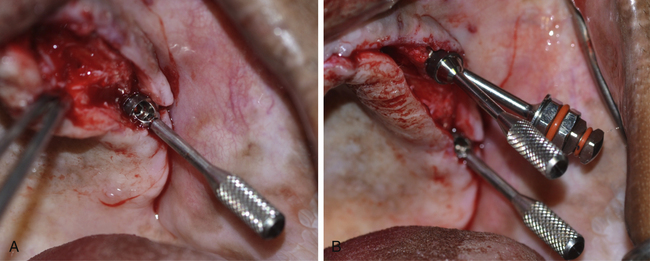
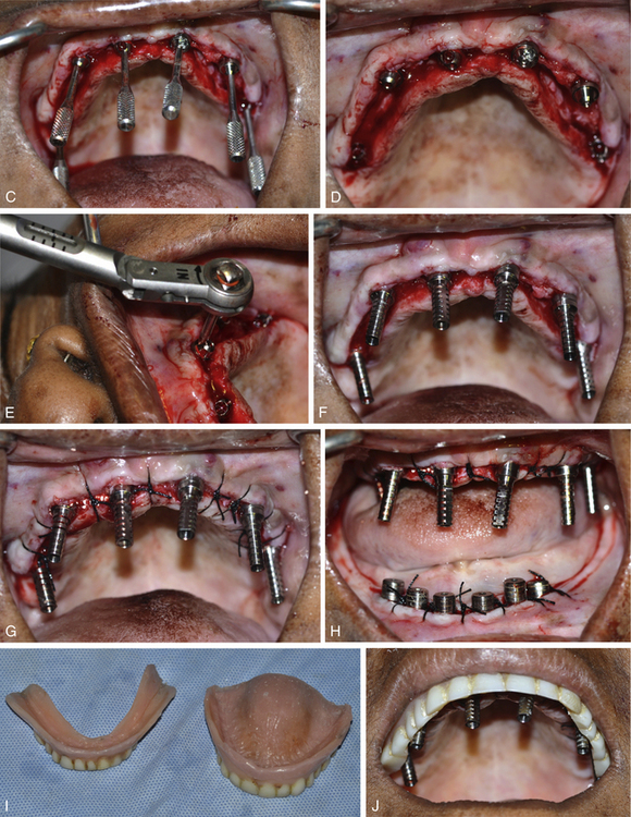
Fig 22.12 (A–C) The 30° multiunit abutments are placed on top of the all four posterior implants whereas the 17° multiunit abutments are placed on top of the both anterior implants.(D) Abutment mounts are removed and (E) the abutment screws are tightened at 15 Ncm using a torque ratchet. (F) The temporary titanium cylinders are screwed on top of the multiunit abutments using the connection screw and (G) flap is sutured. (H) Lower implants are also uncovered and healing abutments are inserted. (I) The patient’s old dentures. (J) Upper denture is prepared and tried in the mouth for its passive seating through the abutments.
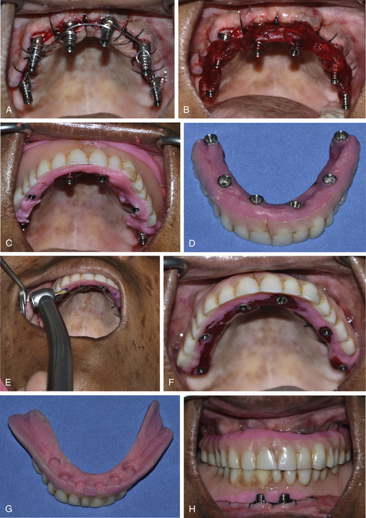
Fig 22.13 (A and B) All the abutments are splinted using a stainless steel wire, which is further reinforced using pattern resin. (C) The self-cure acrylic is mixed, filled into the denture which is accurately seated in the mouth at the correct position. (D) After the acrylic has set, the connection screws of the abutments are unscrewed and the denture along with the abutments is removed from the mouth. The prosthesis is finished, polished, and fixed over the multiunit abutments. (E and F) All the necessary occlusal adjustments are made in the mouth. (G) Relined lower denture. (H) Upper fixed and lower removable provisional prosthesis delivered on the same day as All-on-6 surgery.
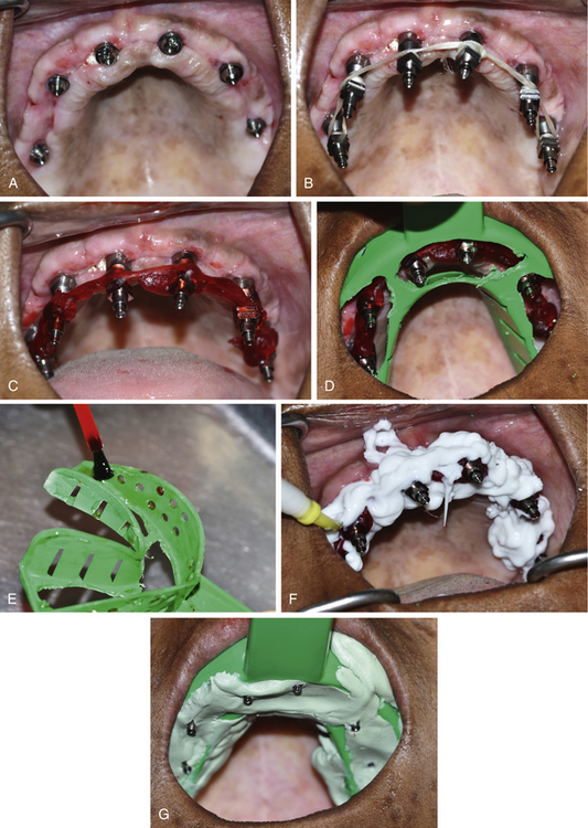
Fig 22.14 (A) Healing after 6 weeks, when the provisional prosthesis is removed for the impression procedure. (B) The open tray impression abutments are placed over the multiunit abutments and splinted using dental floss and (C) further reinforced using the pattern resin to avoid any movement of the abutments in respect to each other during the impression transfer. (D) A custom tray is prepared and tried in the mouth for its passive seating. (E) Tray is painted with tray adhesive. (F) The light body impression material is appropriately flowed under and all around the impression abutments and (G) the tray filled with putty is accurately seated in the mouth.
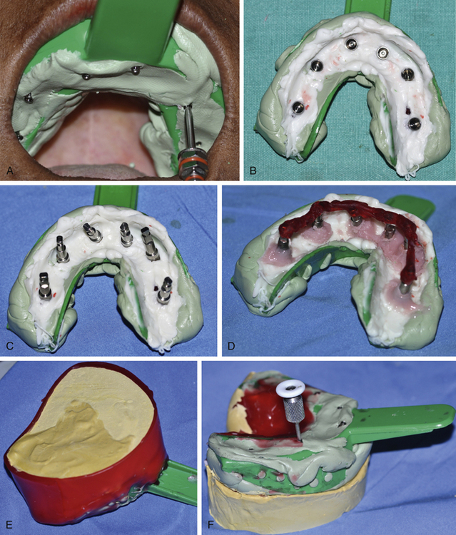
Fig 22.15 (A) The long fixation screws, emerging out of the impression, are unscrewed (B) before removing the impression from the mouth. (C) The abutment analogues are assembled with the impression abutments. The abutment analogues are splinted together using pattern resin to avoid their micromovements in the stone plaster during the prosthetic steps in the laboratory. (D) The soft tissue replicating material is poured around the abutment analogue connections. (E) The impression is further poured using hard stone plaster. (F) The fixation screws are again unscrewed before removing the impression from the working cast.
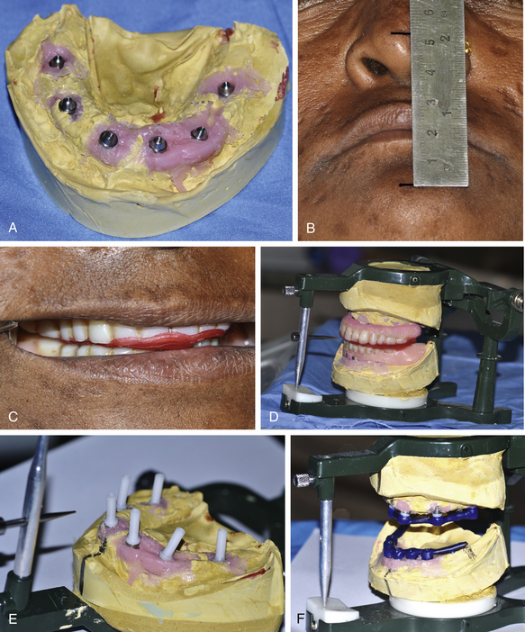
Fig 22.16 (A) The abutment analogues in the working cast. (B) The vertical height of occlusion is recorded at the centric position and (C) bite registration is done using the old prosthesis. (D) The final working casts are mounted on the articulator at the similar maxillo-mandibular relation. (E) The castable plastic abutments are screwed over the abutment analogues using fixation screws. (F) The wax pattern is prepared to fabricate a cast bar framework for upper and lower prosthesis.
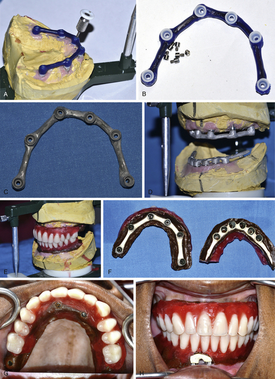
Fig 22.17 (A and B) The fixation screws are unscrewed and the wax pattern along with castable abutments are removed from the cast. (C) The fixation screws are separated and the whole wax pattern along with castable abutments is cast to fabricate a bar of the Ni–Cr or titanium metal, (D) which is screwed over the working casts. The ceramic wash opaque can be used over the bar to avoid metal display through the thin acrylic. (E) The base plate is adapted over the bar and the teeth setting is done in the usual fashion. (F–H) The upper and lower bar framework along with teeth setting are tried in the mouth to check the passive seating of the bar as well as the occlusion.
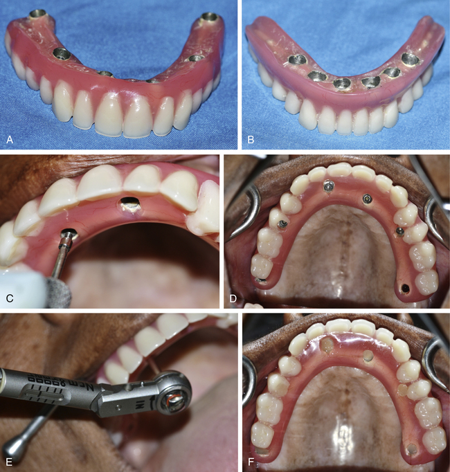
Fig 22.18 The finally acrylized upper and lower hybrid prosthesis. (A and B) A cement-retained hybrid prosthesis is fabricated for the lower arch. (C and D) The upper prosthesis is seated over the multiunit abutments and screwed using the fixation screws. (E) The torque ratchet is used to finally tighten the fixation screws at the moment of 15 Ncm. (F) The screw holes are filled with gutta-percha and covered over with flowable composite. The final 14-unit All-on-6 prosthesis is fixed in the mouth.
CASE REPORT-2
All-on-6 implant procedure for both arches with pterygoid implants in the posterior maxilla (Figs 22.20–22.35).
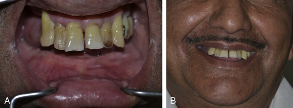
Fig 22.20 (A) A-50-year old male presented with severely resorbed mandibular ridge (he wore a removable ridge-supported denture); and a few teeth in the upper jaw were present, most of them were mobile and needed extraction. (B) On smiling, the patient did not show the marginal gingiva and so did not need any ridge reduction for the maxillary bone during the implant placement surgery.
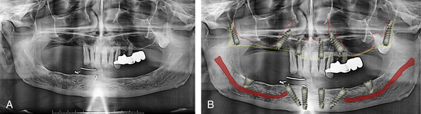
Fig 22.21 Panoramic radiograph shows that hardly any bone is available bilaterally under the maxillary sinuses. A minimum amount of bone is available bilaterally posterior to the sinuses to insert the posterior-most implants. Moreover, an impacted maxillary third molar was also seen on left side, which could hinder placement of implant in the tuberosity. The ridge in the anterior region of the maxilla as well as mandible looked adequate for the insertion of four implants with distal tilting of the posterior implants. The placement of only four implants (All-on-4™) would have resulted in the possibility of a 10- to 12-unit prosthesis but the patient expressed the desire for a 14-unit prosthesis for both arches and that needed the addition of two more implants in the posterior region. Thus for the maxilla, the placement of two additional implants in the maxillary tuberosity with their engagement in the medial pterygoid process was planned. For the mandible, the addition of two more implants with large diameter and short length (5 × 8 mm) in the posterior mandible (in the buccal shelf region) were planned. (A) Immediate extraction of impacted maxillary molar was planned before the placement of implant in the pterygoid process. (B) The panoramic radiograph with the simulated implants shows the planned positions and angulations of all the implants.
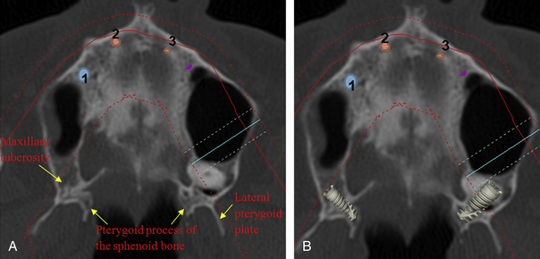
Fig 22.22 (A) The axial view of the dental CT scan shows the location and direction of the pterygoid process of the sphenoid bone in respect of the maxillary tuberosity and (B) the planned axial position and direction of the posterior implants.
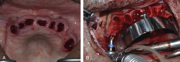
Fig 22.23 (A) All the front maxillary teeth were pulled out and mucoperiosteal flaps were elevated to expose the maxillary ridge as well as the lateral wall of the sinus. The anterior wall of the sinus was bilaterally explored and marked by preparing a small opening through the lateral wall of the sinus. (B) The All-on-4™ guide was seated in the mouth and implant osteotomies were prepared with distal tilting of the posterior implants at 45°.
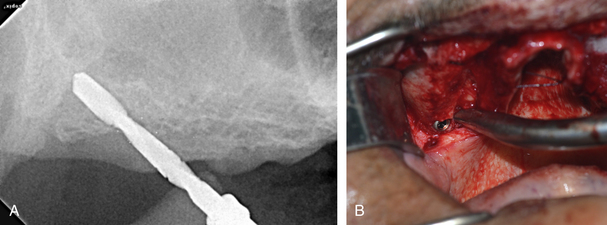
Fig 22.24 The osteotomy for the right posterior-most implant was prepared through the maxillary tuberosity and right up to the medial pterygoid process of the sphenoid bone. (A) The direction of the drill in respect of the posterior wall of the sinus was assessed by taking step by step radiographs during osteotomy preparation. (B) The pterygoid implant in place. The inserted implant achieved primary stability of more than 35 Ncm.
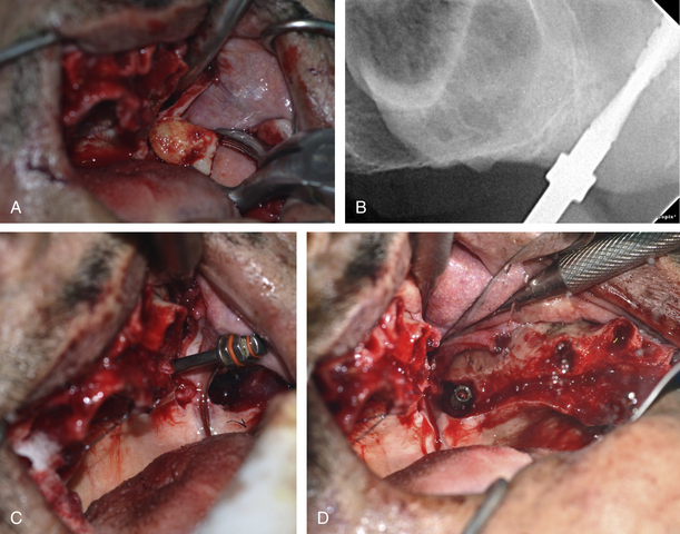
Fig 22.25 (A and B) The impacted third molar on the left side was extracted and implant osteotomy was prepared through the extraction socket and (C) the implant was inserted in the medial pterygoid process. As the implant apex had been inserted into the high-density medial pterygoid process, the inserted implant achieved primary stability of more than 35 Ncm. (D) But the finally inserted implant showed a large peri-implant extraction socket space at its cervical third which needed to be grafted.
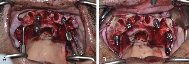
Fig 22.26 All implants were inserted at their planned positions with high primary stability. The apexes of all four anterior implants were stabilized into the high-density nasal floor to achieve high primary stability. (A) The appropriate multiunit abutments were inserted on all six implants. (B) Further, the abutment mounts were removed and healing abutments were inserted on top of all the multiunit abutments.
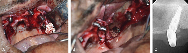
Fig 22.27 (A and B) The peri-implant socket spaces around the left pterygoid implant were grafted using bone substitute. (C) The post implant radiograph shows accurate implant insertion and grafting.
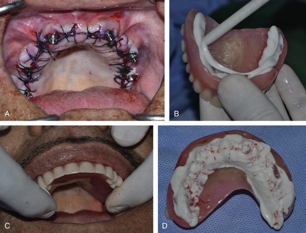
Fig 22.28 (A) The flap was sutured with the healing abutments emerging out of the tissues. (B–D) The indexes of the implant positions were transferred to the prefabricated denture using the light body silicon impression material.
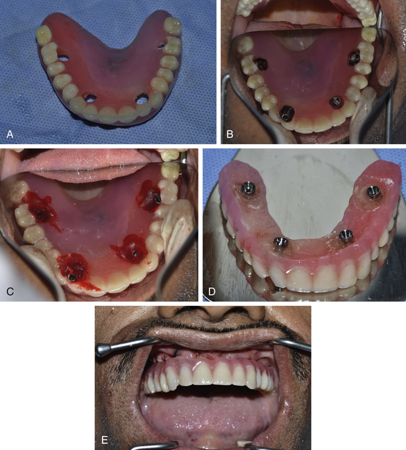
Fig 22.29 (a) The holes were prepared through the denture at the indexed positions. The healing abutments of four anterior implants were removed and replaced with the titanium cylinders. (B) The denture was seated at the correct position with the titanium cylinders emerging out of the holes. (C) The pattern resin was carefully filled around the titanium cylinders and once it had set in the mouth, the titanium cylinders were unscrewed to remove the denture from the mouth. Self-cure acrylic was filled into the deficiencies around the cylinders. (D and E) The palatal extension of the denture was removed and the denture was finished, polished and screwed in the mouth over the four anterior implants. The patient was recalled on the next day for the insertion of the lower implants.
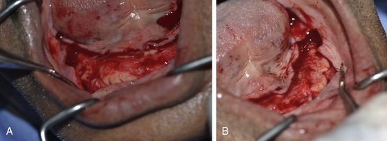
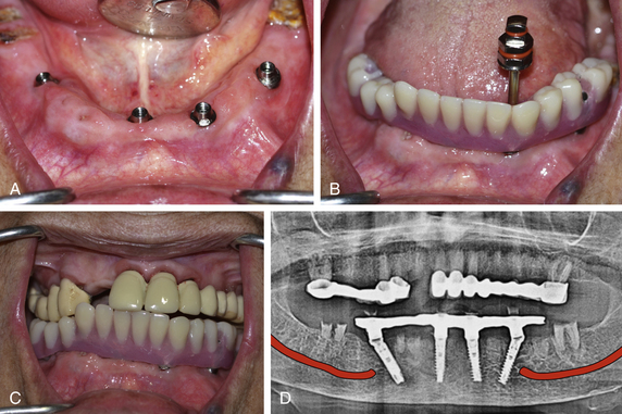
Fig 22.30 (A and B) For the lower arch, the mucoperiosteal flap was elevated to expose the ridge and the mental foramina were bilaterally explored.
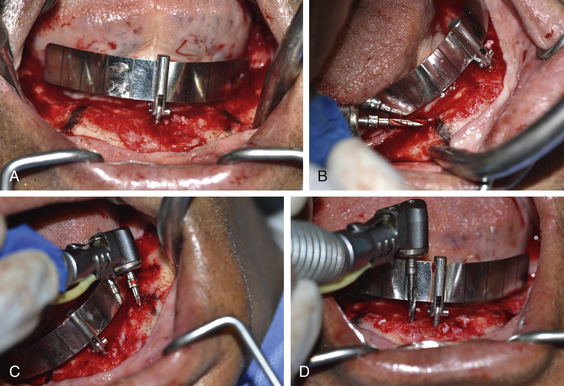
Fig 22.31 (A) The position of the mental foramina was marked on the ridge using a sterile HB pencil and the All-on-4™ guide was seated in mouth. (B and C) The osteotomies for the two posterior implants were prepared with distal tilting and keeping final drill position 2 mm anterior to the mental foramina. (D) The straight osteotomies for two anterior implants were prepared.
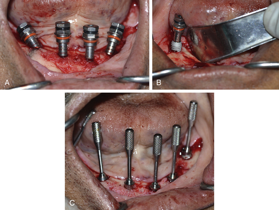
Fig 22.32 (A) Four anterior implants at their final positions with distal tilting of the two posterior implants at 45° to the long axis. (B) Two implants were placed at the most-posterior positions (into the buccal shelf region). (C) The appropriate multiunit abutments were inserted on the top of all the implants.
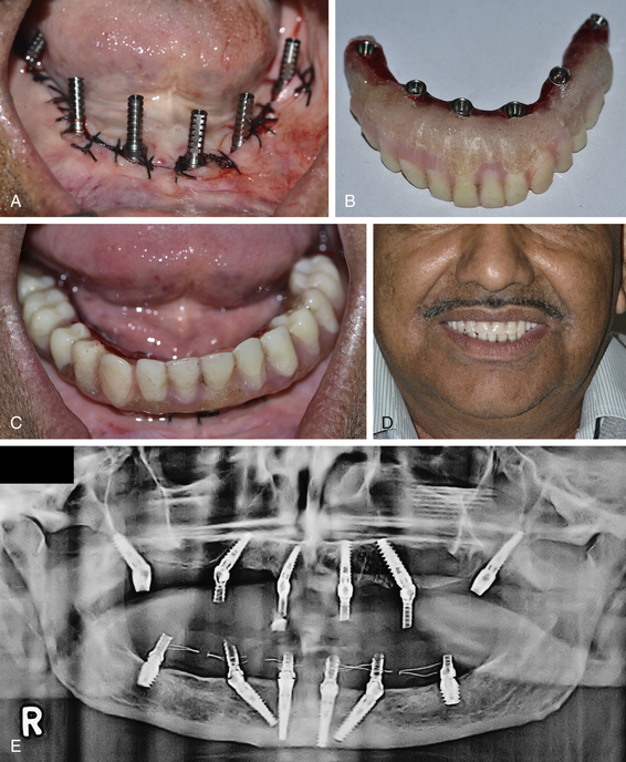
Fig 22.33 (A) Temporary titanium cylinders were placed on top of the multiunit abutments. The prefabricated lower denture was prepared and seated in the mouth with the cylinders emerging out of the holes prepared in the denture. Further, the cylinders were connected to the denture using pattern resin and removed from the mouth along with the cylinders. (B) The denture was finished, polished, and (C) screwed over lower six implants. (D) Maxillofacial view of the patient after the upper and lower provisional prosthesis were fixed in the mouth. Patient was rehabilitated with fixed prosthesis in 2 days. (E) Postimplantation radiograph shows that all the implants have been inserted at the desired positions.
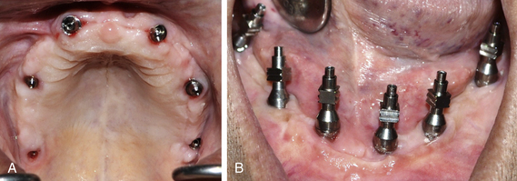
Fig 22.34 (A and B) The healing of the tissue as seen on removing the provisional prosthesis after 4 months for prosthetic procedures. The impression procedures, bite registration, and try-in for the definitive prosthesis were done in the same way as described in the Case Report-1.
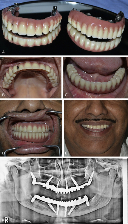
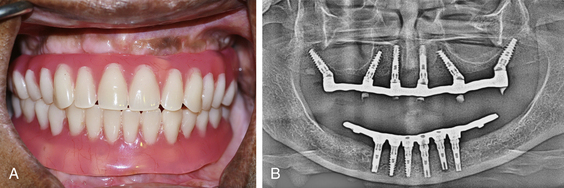
Fig 22.35 (A) Upper and lower screw-retained final prosthesis. (B) Upper prosthesis after fixing over the implants. (C) Lower prosthesis after fixing over the implants. (D) Finally fixed upper and lower prosthesis in occlusion. (E) Maxillofacial view of the patient after rehabilitation. (F) Post loading radiograph showing accurately performed All-on-6 procedure with pterygoid implants in the posterior maxilla.
A 50-year-old male was referred to the author for full mouth rehabilitation with bilateral sinus grafting. On examination, the patient was fit for implant as well as sinus grafting surgeries. On discussion, the patient expressed the desire for immediate restoration of his aesthetics with a fixed prosthesis as he was a speaker at business meetings and conferences and could not manage with the removable prosthesis. He also desired to complete the treatment in the shortest possible time span without much grafting and long waiting periods. Conventional implantation obviously required the sinus grafting procedure with delayed implant placement after the graft maturation period of a minimum of 6 months. It further required, 6 months of subgingival healing for the implants could also be necessary. So all in all, the case could have been completed only in more than 1 year and with multiple surgical steps. To minimize surgical steps, avoid the sinus grafting procedure, for immediate restoration, and to finish the treatment in a short span of time, the All-on-6 technique was planned for this case.
CASE REPORT-3
CT guided flapless placement of four implants with distal tilting of posterior implants (Figs 22.36–22.40).
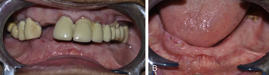
Fig 22.36 (A and B) A 78-year-old female patient presented with upper intact dentition and a missing lower one and desired to have fixed teeth for the lower arch.
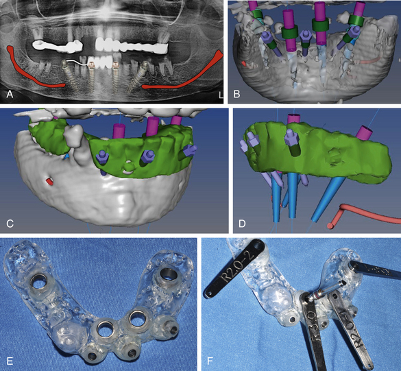
Fig 22.37 (A) Four implants to support a 12-unit fixed hybrid prosthesis is planned; the posterior implants needed to be tilted up to 45° to minimize the length of distal cantilevers. Keeping the patient’s age in mind, the minimal invasive CT guided flapless implant placement procedure is planned. (B–D) The implant dimensions, their positions and angulations are planned using the dental CT planning software and the files are exported to the CAD/CAM milling centre (Pink city cera dental Lab, Jaipur). (E) Using the exported files, the CAD/CAM centre fabricated an accurate soft tissue-supported implant insertion guide. (F) The special sleeves are used to accurately drill for a particular implant.
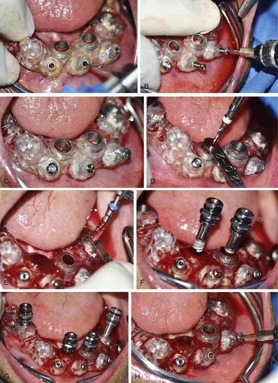
Fig 22.38 (A–C) The guide is accurately seated over the soft tissue ridge and immobilized using long fixation screws. (D and E) The implant osteotomies are prepared through the guide using special sleeves and (F and G) implants are inserted. (H) The guide is removed after all the implants have been installed.
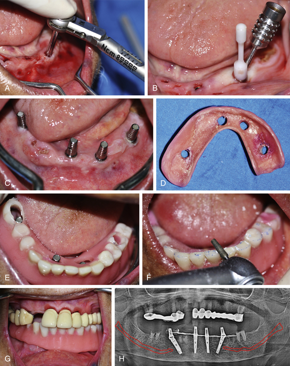
Fig 22.39 (A) All the implants attained primary stability more than 35 Ncm. (B) The appropriately selected multiunit abutments are placed over the implants and (C) straight abutments are fixed on top of multiunit abutments. (D) The patient’s old denture is prepared and (E) checked for its passive seating in the mouth. (F and G) The provisional prosthesis is fixed over the implants on the same day of implant placement and necessary occlusal adjustments are made in mouth. (H) Post implantation radiograph.
CASE REPORT-4
Full mouth rehabilitation using tilted implant concept (Courtesy: Amir Gazmawe, Israel). (Figs 22.41–22.50).
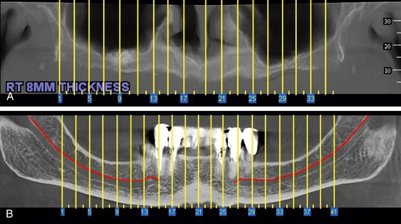
Fig 22.41 (A and B) Panoramic CT images of the maxilla and mandible showing inadequate bone height in the subantral region and over the mandibular canal to insert adequately long implants without performing any bone augmentation procedure. Four implants in the anterior region of each arch are planned with distal tilting of posterior implants to minimize the distal cantilevers.
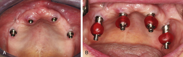
Fig 22.42 (A) Four implants in place with multiunit abutments. (B) Open tray impression abutments placed on top of the multiunit abutments.
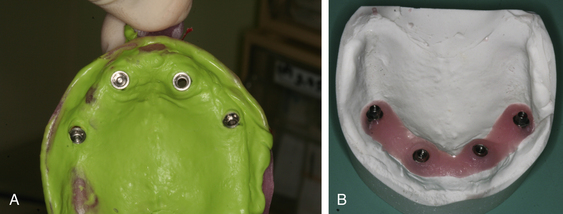
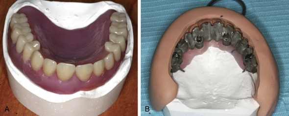
Fig 22.44 (A and B) Patient’s old denture is seated over the cast and a teeth index is made using silicon putty, which is used to cast the metal framework at the ideal position.
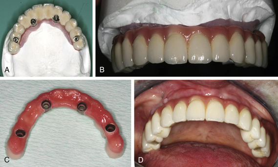
Fig 22.45 (A–D) The final screw-retained ceramic prosthesis, which is screwed over the upper implants.
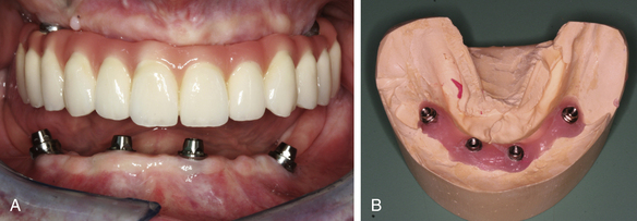
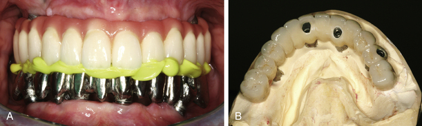
Fig 22.46 (A) Four implants are placed in the lower arch with distal tilting of posterior implants. (B) The impression is made and working cast is prepared in the same way as mentioned before.
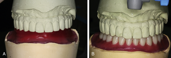
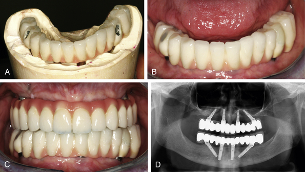
Fig 22.47 (A) Jaw relation is recorded and casts are mounted on the articulator at the centric position. (B) The tooth setting is done in ideal occlusion.
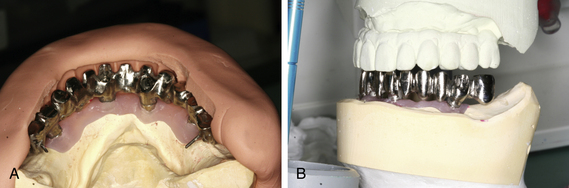
Fig 22.48 (A and B) Teeth indexing is done using silicon putty and the metal framework of an ideal shape and position on the cast.
3. Nerve injury during posterior implant placement in the mandible. It can be avoided by properly exploring the mental foramina and starting drilling a minimum of 4 mm anterior to it. The presence of the anterior loop should be clearly evaluated in the radiographs, dental CT scan and/or inserting a blunt explorer in the mental foramina. If the anterior loop is present, the implant should be positioned a minimum of 2 mm anterior to the anterior loop. For instant radiographic evaluation after flap elevation, a pilot drill is placed over the facial plate anterior to the mental foramina and a radiograph is taken to evaluate the appropriate direction anterior to the loop. If nerve injury has already been occurred, osteotomy preparation is redirected to the correct direction and the implant is placed. If patient complains of any paraesthesia on the chin and lip of the side involved, proper measures should be taken to manage the paraesthesia (for more information about ‘management of nerve injury’ refer to in the Chapter 24 ‘Complications and management’).
4. Fracture of distal cantilevers of the provisional all acrylic bridge. This is the most common complication in the All-on-4™ technique and it can be avoided by avoiding distal cantilevers in the acrylic prosthesis or by using high-strength pattern resin as the base of the acrylic bridge. This complication is very uncommon in All-on-6 procedures as it does not usually require the distal cantilevers.
5. Fracture of teeth from the definitive prosthesis. Usually a screw-retained hybrid or ceramic prosthesis is used as the final prosthesis in All-on-4™ or All-on-6 techniques, hence if it is a hybrid prosthesis it can be easily repaired in the mouth using acrylic or composite (Fig 22.51A and B). In case of big fractures of hybrid prostheses or if the ceramic chips off from the ceramic prosthesis, the prosthesis can be unscrewed/retrieved from the implants and repaired in the laboratory.
6. Food impaction under the prosthesis. Besides normal teeth brushing, interdental brushes should be regularly used by the patient to clean the tissue surface of the denture. The waterpik is a new invention and very useful in the cleaning of such prostheses. The prosthesis can be unscrewed from the mouth and polished in the laboratory as and when required (Fig 22.52A–C).
7. Wearing out of the teeth of hybrid prostheses. The prosthesis can be unscrewed from the implant and a new set of teeth can be acrylized over the same framework in the laboratory.
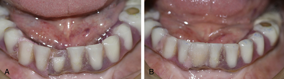
Fig 22.51 (A) Traumatic fracture of a tooth from the All-on-4™ hybrid prosthesis, (B) repaired in the mouth using acrylic.
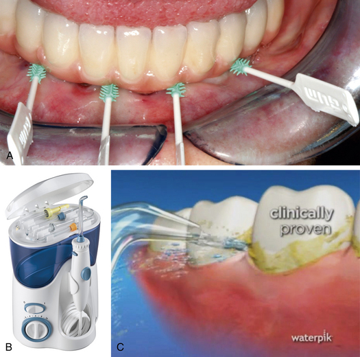
Fig 22.52 (A) Interdental brushes should be used to clean the tissue surface of the All-on-4/All-on-6 prosthesis. (B and C) The waterpik is a new invention and very useful to clean full-arch implant prosthesis as it offers multiple water jets, as well as flossing and brushing tips to reach the difficult areas under and over the prosthesis.
Summary
In several cases, the tilted implant concept can be an ultimate option to restore full-arch cases by avoiding large volume of bone augmentations such as sinus grafting, block grafting etc. The placement of only four implants with distal tilting of the posterior implants usually allows the fixing of a restoration with a 12-unit prosthesis, which offers several advantages such as immediate loading in most cases using an all acrylic bridge, minimized distal cantilevering, placement of posterior implants longer than usual with higher stability, and less invasive procedure because only one surgery is done to insert implants. For a few patients who desire complete arch prosthesis, two additional implants can be added in the posterior region such as in the tuberosity and/or medial pterygoid process in the maxilla and in the buccal shelf region in the mandible to support a 14-unit prosthesis. The accurate exploration of the anterior wall of the sinus in the maxilla and mental foramina in the mandible is mandatory to place posterior implants at the desired positions and with the required distal tilting. To appropriately tilt the posterior implants an All-on-4™ Malo guide should be used. The posterior implants should be tilted distally up to a maximum of 45° to avoid parallelism problems during prosthetic construction. The placement of implants in the medial pterygoid process may need meticulous treatment planning using dental CT scan and skilled surgical approach to install the implant at the desired position and angulation. Often the implants placed in the pterygoid process show extreme angulation in respect to the other implants; to restore such cases, flat connection abutments can be used for the pterygoid implants in place of multiunit abutments. In the All-on-6 technique, the teeth set should end well anterior to the posterior-most implants to avoid cheek bite problems and for easy approach to the posterior-most connection screw. An accurate impression transfer with the open tray technique is mandatory to avoid prosthetic passive seating errors. The posts should be splinted together using pattern resin to avoid their movement in respect to each other during impression transfer. The screw-retained hybrid prosthesis should be preferred over the cement-retained ceramic prosthesis because of many advantages. It is cost effective, more aesthetic, light weight, easy to repair, and retrievable. Long-term maintenance and regular follow-up visits to the dental office are required for the long-term success of the prosthesis as well as implants.
Malo P., Nobre M., Lope A. The use of computer-guided flapless implant surgery and four implants placed in immediate function to support a fixed denture: preliminary results after a mean follow-up period of thirteen months. J Prosthet Dent. 2007;97(6 Suppl):86–95.
Maló P., Rangert B., Dvärsäter L. Immediate function of Brånemark implants in the aesthetic zone: a retrospective clinical study with 6 months to 4 years follow-up. Clin Implant Dent Relat Res. 2000;2:138–146.
Krekmanov L., Kahn M., Rangert B., et al. Tilting of posterior mandibular and maxillary implants of improved prosthesis support. Int J Oral Maxillofac Implants. 2000;15:405–414.
Adell R., Eriksson B., Lekholm U., et al. A long-term follow-up study of osseointegrated implants in the treatment of totally edentulous jaws. Int J Oral Maxillofac Implants. 1990;5:347–359.
Balshi T.J., Wolfinger G.J. Immediate loading of Brånemark implants in edentulous mandibles. A preliminary report. Implant Dent. 1997;6:83–88.
Schnitman D.A., Wohrle P.S., Rubenstein J.E., et al. Branemark implants immediately loaded with fixed prosthesis at implant placement: ten year results. Int J Oral Maxillofac Implants. 1997;12:495–503.
Duyck J., Van Oosterwyck H., Vander Sloten J., et al. Magnitude and distribution of occlusal forces on oral implants supporting fixed prostheses: an in vivo study. Clin Oral Implants Res. 2000;11:465–475.
Van Steenberghe D., Glauser R., Blomback U., et al. A computed tomographic scan-derived customized surgical template and fixed prosthesis for flapless surgery and immediate loading of implants in fully edentulous maxillae: a prospective multicenter study. Clin Implant Dent Relat Res. 2005;7(Suppl. 1):S111–S120.
Ericsson I., Randow K., Nilner K., et al. Early functional loading of Brånemark dental implants: 5-year clinical follow-up study. Clin Implant Dent Relat Res. 2000;2:70–77.
Branemark P.I., Svensson B., van Steenberghe D. Ten year survival rates of fixed prostheses on four to six implants Ad Modum Branemark in full edentulism. Clin Oral Implants Res. 1995;6:227–231.
Fortin Y., Sullivan R.M., Rangert B. The Marius implant bridge: surgical and prosthetic–rehabilitation for the completely edentulous upper jaw with moderate to severe resorption: a 5-year retrospective clinical study. Clin Implant Dent Relat Res. 2002;4:69–77.
Aparicio C., Perales P., Rangert B. Tilted implants as an alternative to maxillary sinus grafting: a clinical, radiographic and periotest study. Clin Implant Dent Relat Res. 2001;3:39–49.
Maló P., Rangert B., Nobre M. “All-on-Four” immediate function concept with Brånemark System implants for completely edentulous mandibles: a retrospective clinical study. Clin Implant Dent Relat Res. 2003;5:S2–S9.
Chow J., Hui E., Liu J., et al. The Hong Kong Bridge protocol. Immediate loading of mandibular Brånemark fixtures using a fixed provisional prosthesis: preliminary results. Clin Implant Dent Relat Res. 2001;3:166–174.
Maló P., Rangert B., Nobre M. “All-on-4” immediate-function concept with Brånemark System implants for completely edentulous maxilla: a 1-year retrospective clinical study. Clin Implant Dent Relat Res. 2005;7:S88–S94.
Rosen A., Gynther G. Implant treatment without bone grafting in edentulous severely resorbed maxillas: a long-term follow-up study. Oral Maxillofac Surg. 2007;65:W10–1016.
Mal P., Rangert B., Nombre M. ‘All on Four’ immediate function concept with Branemark System implants for completely edentulous maxilla: a 1-year retrospective clinical study. Clin Implant Dent Relat Res. 2003;7(Suppl. 1):588–594.
Davo Rodriguez, Malevez C., Rojas J. Immediate Function in atrophic upper jaw using Zygoma implants. J Prosthet Dent. 2007. (Submitted)
Tulasne J.F. Osseointegrated fixtures in the pterygoid region. In: Worthington P., Branemark P.I., eds. Advanced osseointegration surgery. Applications in the maxillofacial region. Chicago, USA: Quintessence Publ. Co, Inc; 1992:182–188.
Graves S.L. The pterygoid plate implant: a solution for restoring the posterior maxilla. Int J Periodontics Restorative Dent. 1994;4:512–523.
Parel S., Branemark P.I., Ohrnell L.O., Svensson B. Remote implant anchorage for the rehabilitation of maxillary defects. J Prosthet Dent. 2001;86:377–381.
Vrielinck L., Politis C., Schepers S., Pauwels M., Naert I. Image-based planning and clinical validation of zygoma and pterygoid implant placement in patients with severe bone atrophy using customized drill guides. Preliminary results from a prospective clinical follow-up study. Int J Oral Maxillofac Surg. 2003;32:7–14.
Hirsch J.-M., Henry P., Andreasson L., et al. A clinical Evaluation of the Zygoma Fixture. One-year follow-up at 16 clinics. J Oral Maxillofac Surg. 2004;9(Suppl):22–29.
Aparicio C., Arevalo X., Ouzzani W., Granados C. A retrospective clinical and radiographic evaluation of tilted implants used in the treatment of severely resorbed edentulous maxilla. Appl Osseointegrat Res. 2003;1:17–21.
Randow K., Ericsson I., Nilner K., Peterson A., Glantz P.O. Immediate functional loading of Brånemark dental implants. An 18-month clinical follow-up study. Clin Oral Implants Res. 1999;10:8–15.
Brånemark P.I., Engstrand P., Öhrnell L.O., et al. A new treatment concept for rehabilitation of the edentulous mandible. Preliminary results from a prospective clinical follow-up study. Clin Implant Dent Relat Res. 1999;1:2–16.
Örtorp A., Jemt T. Clinical experience of CNC-milled titanium frameworks supported by implants in the edentulous jaw: a 3-year interim report. Clin Implant Dent Relat Res. 2002;4:104–109.
Peto R., Pike M.C., Armitage P., et al. Design and analysis of randomized clinical trials requiring prolonged observation of each patient: II. Analysis and examples. Br J Cancer. 1977;35:1–39.
Petersson A., Rangert B., Randow K., Ericsson I. Marginal bone resorption at different treatment concepts using Brånemark dental implants in anterior mandibles. Clin Implant Dent Relat Res. 2001;3:142–147.
Chaushu G., Chaushu S., Tzohar A., Dayan D. Immediate loading of single tooth implants: immediate versus nonimmediate implantation. A clinical report. Int J Oral Maxillofac Implants. 2001;16:267–272.
Hui E., Chow J., Li D., Liu J., Wat P., Law H. Immediate provisional for single-tooth implant replacement with Brånemark System: preliminary report. Clin Implant Dent Relat Res. 2001;3:79–86.
Esposito M., Hirsch J.M., Lekholm U., Thomsen P. Failure patterns of four osseointegrated oral implant systems, J Materials Science Materials in Medicine. 1997;(Suppl 8):843–847.