Screen-Film Radiographic Artifacts
At the completion of this chapter, the student should be able to do the following:
1 Visually identify the screen-film radiographic artifacts shown in this chapter.
2 List and discuss the three categories of screen-film artifacts.
3 Explain the causes of exposure artifacts.
4 Describe the types of artifacts caused during film processing.
5 Discuss how improper handling and storage of film can cause artifacts.
FOR STUDENT radiographers, one of the most interesting areas of study is the identification of image artifacts. Most educational programs have an extensive film file of artifacts, from pi lines to necklaces on chest radiographs. It is fun to identify such artifacts and their causes.
However, artifacts must be prevented. Identification of the artifact and its cause is critical for screen-film radiography quality control (QC). It is important for every radiographer to be alert to artifacts and their origins.
The cause of the artifact must be removed to prevent recurrence of the same problem in subsequent radiographs. Finally, records of artifacts must be kept to indicate trends; for example, if sludge artifacts show up more than once before processor cleaning, consider cleaning the processor more frequently.
Artifacts are undesirable optical densities or blemishes on a radiograph or any other medical image. An artifact is something in the image that looks like it was created by the object but was in fact created by the process.
 An artifact is any irregularity on an image that is not caused by the proper shadowing of tissue by the primary x-ray beam.
Screen-film radiographic artifacts can interfere with the visualization of anatomical structures and can lead to misdiagnoses. Artifacts can be controlled when their cause is identified. Generally, radiographic artifacts occur in three areas: exposure, processing, and handling. Figure 19-1 provides a classification scheme of the artifacts one is likely to see in screen-film radiography.
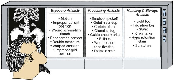
Exposure Artifacts
Exposure artifacts generally are associated with the manner in which the radiographer conducts the examination. Incorrect screen-film match, poor screen-film contact, warped cassettes, and improper positioning of the grid all can lead to such artifacts.
Improper patient position, patient motion, double exposure, and incorrect screen-film radiographic technique can result in very poor images that some would call artifacts. Such examples of poor technique have been shown to result in the largest number of repeat examinations.
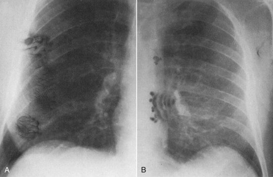
Improper preparation of the patient can lead to disturbing artifacts (Figure 19-2). However, these do not occur when the radiologic technologist properly instructs and prepares the patient.
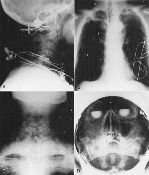
FIGURE 19-2 A, Lateral cervical spine of a patient with a “Black Eyed Peas starter set.” B, The patient’s glasses were not removed from the shirt pocket. C, The ice bag under the neck was not removed during this anteroposterior (AP) cervical spine view. D, This Waters view was properly coned, but the bifocals, earrings, and dental apparatus should have been removed. (Courtesy Paul Laudicina, College of Dupage.)
Patient preparation is essential for producing artifact-free images. Artifacts on or worn by the patient often are concealed by clothing. Among these items are necklaces, pendants, hearing aids, chains, earrings, body and facial piercings, zippers and catches, and a variety of jewelry. Even supposedly “radiolucent” patient change gowns can have radiopaque parts, including traces of staining from contrast media.
In cases of trauma, pins, fasteners, dressings, and splints often have to remain in place because their removal could be dangerous to the patient. Internal artifacts from prostheses to dental fillings obviously cannot be removed and, similar to trauma cases, this should be noted on the examination request form. This is particularly important for the patient who is to undergo a magnetic resonance imaging (MRI) examination later.
A radiograph with motion appears blurred. The patient may have moved or may not have breathed according to the radiographer’s instructions. Clear instructions are required to encourage understanding and cooperation in patients.
Double exposures are also avoidable. When radiographers mix up cassettes, double exposures can occur; repeat examination is required.
Positioning errors can cause artifacts. If the patient is positioned for examination when the x-ray tube is not centered to the table or Bucky tray, grid cutoff artifacts may occur.
Artifacts can occur if the wrong film is loaded into a cassette. If high-contrast, single-emulsion mammography film is loaded into a radiographic cassette, an unexpected image results. Cassettes that have not been checked for proper screen-film contact produce smoothness in the area of poor contact that obscures detail and constitutes an artifact.
When one is trying to locate an object that has been swallowed, this is not an artifact. On the other hand, if such an object appears on an image unexpectedly, it is an artifact. Table 19-1 summarizes the exposure artifacts discussed here.
TABLE 19-1
| Appearance on the Radiograph | Cause |
| Unexpected foreign object such as jewelry | Improper patient preparation |
| Double exposure | Reuse of cassettes already exposed |
| Blur | Improper patient movement, including breathing |
| Grid cutoff artifacts | Improper patient positioning |
| Obscured detail | Poor screen-film contact |
Processing Artifacts
Any number of screen-film radiographic artifacts can be produced during film processing. Most are pressure-type artifacts caused by the transport system of the processor. Pressure-type artifacts usually sensitize the emulsion and appear as higher optical density (OD). Those that scrape or remove emulsion appear as lower OD.
Table 19-2 summarizes the processing artifacts discussed here, as well as some other common artifacts.
TABLE 19-2
| Appearance on the Radiograph | Cause |
| Guide shoe marks | Improper position or springing of guide shoes in turnaround assembly |
| Pi lines | Dirt or chemical stains on rollers |
| Sharp increase or decrease in OD | Dirty or warped rollers, which can leave sludge deposits on film |
| Uniform dull, gray fog | Improper or inadequate processing chemistry |
| Dichroic stain or “curtain effect” | Improper squeezing of processing chemicals from film |
| Small circular patterns of increased OD | Pressure caused by irregular or dirty rollers |
| Yellow-brown drops on film | Oxidized developer |
| Milky appearance | Underreplenished fixer |
| Greasy appearance | Inadequate washing |
| Brittle appearance | Improper dryer temperature or hardener in the fixer |
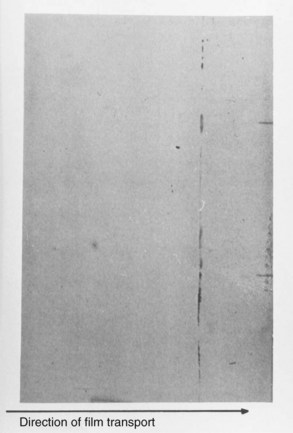
Roller Marks
Guide shoe marks occur when the guide shoes in the turnaround assembly of the processor are sprung or improperly positioned (Figure 19-3). If the guide shoe is used before the developer, the ridges in the guide shoes press against the film, sensitize it, and leave a characteristic mark. Guide shoe marks can be found on the leading edge or the trailing edge of the film parallel to the direction of film travel through the processor.
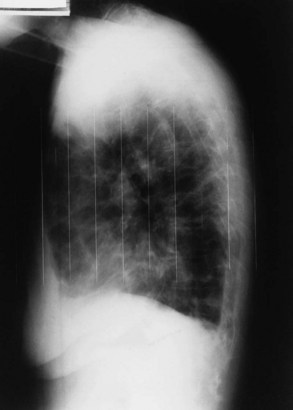
FIGURE 19-3 Guide shoe marks left by an improperly serviced turnaround assembly. (Courtesy Judy Williams, Grady Memorial Hospital, Atlanta.)
Pi lines occur at 3.1416-inch (π) intervals because of dirt or a chemical stain on a roller, which sensitizes the emulsion. Because the rollers are 1 inch in diameter, 3.1416 inches represents one revolution of a roller, and the artifact appears perpendicular to the film’s direction of travel through the processor. Figure 19-4 is an example of pi lines appearing on the same film.
Dirty Rollers
Dirty or warped rollers can cause emulsion pick-off and gelatin buildup, which result in sludge deposits on the film. These artifacts usually appear as sharp areas of increased or reduced OD. Occasionally, particles of sludge are transported through the processor and are actually dried on the film in the dryer.
Chemical Fog
Chemical fog looks like light or radiation fog and is usually a uniform dull gray. Improper or inadequate processing chemistry can result in a special type of chemical fog called a dichroic stain. Dichroic means two colors. The dichroic stain appears as a curtain effect on the radiograph (Figure 19-5). Dichroic stain is a term that is generally applied to all chemical stains.
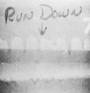
FIGURE 19-5 Excess chemistry runs down the leading edge of the film, creating a dichroic stain “curtain” effect. (Courtesy William McKinney, DuPont Medical Systems.)
Chemical stains on a radiograph can appear yellow, green, blue, or purple. In slow processors, the chemistry may not be squeezed properly from the film, and it either runs down the leading edge of the film or runs up the trailing edge. Both events are referred to as a curtain effect.
Wet-Pressure Sensitization
Wet-pressure sensitization is a common artifact that is produced in the developer tank (Figure 19-6). Irregular or dirty rollers cause pressure during development and produce small circular patterns of increased OD.
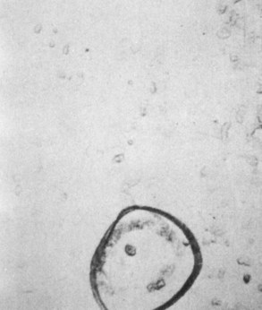
FIGURE 19-6 Wet-pressure sensitization caused by a dirty processor. (Courtesy William McKinney, DuPont Medical Systems.)
Processing artifacts in digital radiography (DR) are different from those with screen-film because the method of producing the visible image is electronic rather than chemical. Image-processing errors can produce bizarre artifacts in DR. Interference with electronic components involved in processing DR images also occurs. Artifacts in DR are discussed in detail in Chapter 21.
Handling and Storage Artifacts
A number of artifacts are caused by improper film storage conditions. Image fog can result if the temperature or the humidity is too high or if the film bin is not shielded adequately from radiation. Pressure marks can occur if the film is stacked too high. Table 19-3 summarizes the storage artifacts discussed here.
TABLE 19-3
Common Handling and Storage Artifacts
| Appearance on Radiographic Film | Cause |
| Light or X-radiation fog | The temperature or humidity is too high. |
| The film bin is inadequately shielded from radiation. | |
| The safelight is too bright, is too close to the processing tray, or has an improper filter. | |
| The film has been left in the x-ray room during other exposures. | |
| Pressure or kink marks | The film is improperly or roughly handled. |
| The film is stacked too high in storage (the weight causes marks). | |
| Streaks of increased OD | The darkroom or cassette has light leaks. |
| Crown, tree, and smudge static | The temperature or humidity is too low. |
| Yellow-brown stain | Thiosulfate is left on the film because of inadequate washing. |
Light or Radiation Fog
White-light leaks in the darkroom or within the cassette cause streaklike artifacts of increased OD. If the safelight has an improper filter, the safelight is too bright, or the safelight is too close to the film processing tray, the image may be fogged. Films left in the x-ray examination room during an exposure can become fogged by radiation. Radiation fog and safelight fog look alike.
Pressure or Kink Marks
Characteristic artifacts can be caused by improper handling or storage either before or after processing. Rough handling before processing can cause scratches and kink marks, such as those shown in Figure 19-7. Although the kink mark may appear as a fingernail mark, it is not. It is caused by the kinking or abrupt bending of film. Both events usually appear as increased OD.
Static
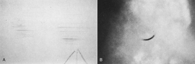
Static is probably the most obvious artifact. It is caused by the buildup of electrons in the emulsion and is most noticeable during the winter and during periods of extremely low humidity. Three distinct patterns of static are crown, tree, and smudge. Tree static and smudge static are illustrated in Figure 19-8.
Hypo Retention
The yellow-brown stain that slowly appears on a radiograph after a long storage time indicates a problem with hypo retention from the fixer. With this event, not all of the residual thiosulfate from fixing was removed during washing, and silver sulfide slowly builds up and appears yellow in the stored radiograph.
Summary
An artifact is an undesirable OD that appears on the screen-film radiograph. Artifacts occur (1) during the radiographic exposure, (2) during processing of the film, and (3) when the film is being handled and stored before or after processing.
Exposure artifacts are a result of examination technique. These include patient motion, positioning errors, wrong screen-film combinations, double exposures, and improper grid positioning.
Processing artifacts are most often pressure blemishes on the film emulsion caused by the roller transport system in the processor. They include sludge from dirty rollers, chemical fog, roller marks, and wet-pressure sensitization.
The most bothersome handling and storage artifacts are those associated with light or radiation fog, kink marks, and static.
1. Define or otherwise identify the following:
2. Why must records be kept when the QC technologist sees artifacts?
4. List the three stages in diagnostic imaging during which artifacts tend to occur.
5. Give three examples of exposure artifacts.
6. How would a radiographer correct a blurred radiograph if it was the result of patient motion?
7. What is the principal reason for double exposures?
8. Name three types of processing artifacts.
10. How do guide shoe marks occur?
11. Explain what 3.1416 inches has to do with pi lines.
12. Describe the causes of wet-pressure sensitization marks.
13. Explain three ways fog can occur on a radiograph.
14. What is the cause of a static artifact on the processed radiograph?
15. List the three types of static artifact patterns.
16. Why is it important for radiographers to be alert to film artifacts?
17. How can one best avoid processor artifacts?
18. What causes grid cutoff artifacts?
The answers to the Challenge Questions can be found by logging on to our website at http://evolve.elsevier.com.