21 Bioinstrumentation
Principles and Techniques
Pearls
• Monitoring and support systems provide valuable information and assistance in managing patient care, but the focus should always be on the patient and family as a first priority.
• Assess the patient's clinical condition before troubleshooting instruments.
• There are many physical characteristics of children that influence the development, use, size, and accuracy of biomedical instruments.
• No single measurement will be as valuable as the evaluation of trends in measurements over time.
• Not all instruments are necessarily valuable or precise.
• ECG waveforms indicate myocardial electrical activity and not the effectiveness of myocardial mechanical function.
• Respiratory monitoring is an invaluable resource to detect cardiopulmonary insufficiency and allow intervention before the development of cardiopulmonary failure.
• The use of mechanical ventilation does not ensure that the child's ventilation is effective. The child's clinical condition is the ultimate indicator of the effectiveness of mechanical ventilation.
• Multimodal monitoring, incorporating several neurologic monitoring parameters, may yield valuable information about the patient's overall clinical status.
Overview of pediatric bioinstrumentation
Bioinstrumentation in the pediatric critical care unit continues to increase in sophistication, paralleling the rapid growth and increasing complexity of pediatric critical care. Currently, a wide variety of instrumentation is available, and can be tailored to the needs of infants and children. The equipment discussed in this chapter is categorized according to the body system for which it is used.
This chapter describes the principles of bioinstrumentation, necessary equipment, specific uses, hazards of devices employed in the care of critically ill children, and troubleshooting techniques. As a first priority, the nurse should always assess the patient's clinical condition before proceeding to troubleshoot the instruments.
Instrumentation may be used to monitor, measure, or support a patient. Monitoring devices can measure patient physiologic parameters and can give warning or advise the clinician of the status of the parameters. Measuring devices regulate components that are administered to the patient, such as intravenous fluids. Patient support systems, such as ventilators, may both monitor and measure while they provide vital support.
For the sake of brevity, types of equipment described in this chapter are called monitoring devices. These devices may be subdivided further into two types: those considered invasive, which break the normal physiologic barriers (e.g., the skin) and those considered noninvasive, which do not break the physiologic barriers and, in some instances, do not even touch the patient.
Not all instruments are necessarily valuable or precise. The value of each device is affected by the skill of the clinicians and biomedical engineers working with the equipment. Karselis87 maintains that the primary purpose of an instrument is to “extend the range and/or sensitivities of man's faculties” and, as such, should do so “with speed, reproducibility, reliability, and cost effectiveness.”
Characteristics of Children that Affect Bioinstrumentation
Although the characteristics of the child that can affect selection and reliability of bioinstrumentation vary with the type of device, there are several key characteristics that must be considered during bioinstrumentation. Key characteristics include the child's body size, cardiovascular structure and function, pulmonary anatomy and physiology, neurologic development and function, metabolic rate, fluid requirements, and immunologic immaturity.
Body Size
Children are obviously smaller than adults. However, children have increased total body surface area in proportion to body mass, which causes higher heat and fluid loss per kilogram body weight than in the adult. Devices requiring exposure of the child to ambient air (e.g., overbed warmers) can increase fluid or heat loss. Compared with adults, infants and children have less absolute surface area available for application of skin electrodes or other contact devices, and this small available surface influences the design and use of some instruments.
Cardiovascular Structure and Function
Several features of the child's cardiovascular system influence the use of biomedical devices:
• Children have small arteries and veins for cannulation. Multiple lumen catheters in smaller sizes may be difficult to keep patent, influencing the choice of catheter and the nursing care required.
• The resting heart rate of the infant and small child is higher than that of the adult. As a result, when tachycardia develops the heart rate may be extremely high, making it difficult to evaluate the cardiac rhythm. A flexible but sensitive cardiac monitor is required that will accurately document changes in the child's heart rate or rhythm, and avoid introduction of errors from movement and other artifacts.
• The major compensatory mechanism for the child with cardiovascular dysfunction is tachycardia. The relatively small stroke volume of the young child is generally near the maximum that can be achieved by the child's small ventricle, so although stroke volume can increase slightly during periods of stress, the major mechanism for increasing cardiac output is an increase in heart rate. If the heart rate falls below normal, cardiac output typically falls. Thus, the child's cardiac output is much more dependent on heart rate than on stroke volume.
• Pulmonary artery wedge pressure may be elevated artificially by the child's rapid heart rate.
• The child has a relatively low systolic, diastolic, and mean arterial blood pressure compared with the adult; these low pressures must be measured accurately by monitoring devices. Quantitatively small changes in blood pressure can indicate qualitatively significant changes in the child's cardiovascular function.
• The technique used to determine cardiac output (CO) by thermodilution may be influenced by the child's limited tolerance of excessive fluid administration. Thermodilution CO calculations are performed in the adult using several 5-10 cc injections that will likely exceed a child's fluid requirements. Therefore the CO computer must be capable of calculating CO based on smaller injectate volumes with an acceptable potential error.
Pulmonary Anatomy and Physiology
The entire respiratory tract of an infant or small child is smaller than that of the adult. In addition, immaturity of components of the respiratory system will affect monitors and supportive devices. Specific considerations include:
• The upper airway of the child is smaller than that of the adult. Therefore, endotracheal and tracheostomy tubes used for children must be smaller. In the past, the tubes used in children were uncuffed. In recent years, evidence has accumulated that cuffed tubes may be as safe as uncuffed tubes and use of cuffed tubes in the operating suite allows more accurate selection of tube size.92
• The small tidal volumes, rapid respiratory rates, and short inspiratory times of children require mechanical ventilators that are able to deliver small tidal volumes accurately in short inspiratory times and at low pressures.
• The major compensatory mechanism for the child with respiratory distress is tachypnea. Respiratory monitoring equipment must be capable of accurately measuring rapid respiratory rates, even when tidal volume is low and chest movement is minimal.
• The infant's small airway closing pressure may be greater than atmospheric pressure, so there may be an increased tendency for alveolar collapse unless continuous positive airway pressure (CPAP) or positive end-expiratory pressure (PEEP) can be provided by pediatric respiratory assist devices.
• The infant's chest wall is very compliant and provides little resistance to expansion during positive pressure ventilation, so visible chest rise should be observed during positive pressure ventilation. However, inadvertent hyperventilation and barotrauma may occur during hand or mechanical ventilation if excessive volume or pressure is provided.
• Although effective inspiratory inflation pressures are the same in normal patients of all ages, the force required to generate inspiratory pressure decreases with decreasing patient age because the lungs are small. Therefore, unless the inspiratory pressure is monitored closely, pneumothorax may be produced during hand ventilation or ventilation with high inspiratory pressure.
• Respiratory work normally accounts for 2% to 6% of the child's total oxygen consumption. When the infant develops respiratory distress, this requirement may be as high as 25% to 30% of the total oxygen consumption.
• A rapid respiratory rate produces increased heat and water loss through the respiratory system. Therefore all respiratory assist devices must heat and humidify inspired air.
Neurologic Development and Function
The infant's skull is thin and fontanelles are present. These characteristics influence the types of intracranial pressure monitoring devices used during infancy.
The critically ill child is typically frightened and uncooperative and is often unable to understand the reasons for monitoring or therapy. Movement artifact can cause interruption or distortion of instrument function or measurements; therefore monitoring devices must be able to differentiate between movement artifact and abnormalities in the child's clinical status.
Metabolic Rate
The child has a higher metabolic rate than the adult and therefore requires greater daily caloric intake per kilogram of body weight. Numerically small changes in the child's caloric intake may create significant changes in nutritional status, including the ability to heal.
Rapid heat loss or inadequate cardiac output, especially in the infant or young child may result in temperature instability. Constant temperature monitoring is required. The infant's oxygen consumption may increase significantly with changes in the ambient temperature.
Fluid Requirements
Infants and small children have a greater proportion of body weight as total body water and extracellular water than older children or adults, yet their absolute fluid requirements are small. Careful attention always must be given to the amounts and types of oral and parenteral fluids that the child receives.
Devices used to regulate the child's IV fluid administration rate and measure urine output must be calibrated in small units. Infusion pumps must be factory tested and clinically evaluated to ensure that they are able to accurately deliver specific fluid volumes and include appropriate alarms.
Immunologic Immaturity
The risk of healthcare-acquired infection is increased among critically ill children when invasive monitoring is performed. Invasive catheters should be used only when clearly indicated and they should be removed as soon as possible. Each child requires close observation for evidence of infection.
General Problems During Monitoring
Although complications and recommendations for each major equipment category are listed at the end of each major section, the following comments are relevant to all types of monitoring equipment. There are three common challenges in critical care units when electrical or mechanical equipment is used:
• Specialized knowledge is required. The nurse must understand the principles and components of each piece of equipment used to understand its usefulness and hazards. If the nurse is unfamiliar with any equipment, the nurse must immediately obtain instructions in use and troubleshooting of the device.
Equipment is continuously being improved and upgraded and, consequently, this impacts interactive software and electronic medical record systems as well. The continuous improvements provide a challenge for ensuring that all staff are competent in the use of the current models of devices.
• Many alarm systems are in use simultaneously. The number of monitoring devices in use and subsequently the number of audible alarms sounding in the critical care unit are increasing dramatically. The sheer numbers of alarms may result in “alarm fatigue,”65 in which clinicians may disable, silence, or ignore alarms when the number, variety, and sounds of the alarms become overwhelming. In addition, alarms may be turned off or malfunction without the knowledge of the bedside nurse. This may allow a problem to progress to a critical state before detection.
If an alarm fails, the nurse is responsible for the consequences that may follow. All alarm settings and functions must be checked at least at the beginning and end of every shift and whenever vital signs are evaluated.
• Equipment introduces risk of infection. Contamination is more likely when invasive equipment is used, but it can also occur with noninvasive equipment.
Instrument Theory and Safety
Most electrical or mechanical monitoring systems include a sensor, a transducer, an amplifier, meters and alarms (Fig. 21-1). The nurse must interact with the patient and monitor at the point at which the device senses the physiologic signal and converts it to an electrical signal. The nurse also can adjust the amplifier and meter with tools such as the “gain” on an ECG monitor. The monitor alarm systems must be adjusted manually to fit the patient's needs.
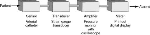
Fig. 21-1 Components of monitoring systems. Most instruments used to monitor critically ill patients require a sensor, a transducer, an amplifier, and a meter. In hemodynamic monitoring systems, the sensor is the vascular catheter that provides access to the vascular pressure signal; the pulsatile vascular signal is converted to an electrical signal by a transducer; an amplifier in the monitor enhances the signal, and the digital display and oscilloscope function as the meter.
Filters that eliminate electrical interference and grounding devices that protect both the patient and nurse from electrical shock are essential components of a monitoring system. All of these elements of bioinstrumentation are discussed in subsequent sections of this chapter.
Definition of Terms
Several terms are used to describe the common properties of electrical energy. The application of these terms to equipment function may be clarified by using the biologic correlate of an electrical system—the cardiovascular (hydraulic) system.87
Current
Electrical current is the flow of electrons past a given point147; electricity is always in motion. Current reflects the number of electrons (negatively charged ions) flowing through a conducting substance per unit of time.
Electrons move from an area of high electron concentration to an area of low electron concentration. In electrolyte solutions (e.g., water), ions move toward ions of the opposite charge. The current flow that is produced by ion movement is measured in amperes (amps). The analog of current in the cardiovascular system is “flow.”
Voltage
Voltage is the unit of potential difference in charge between two points (i.e., “gradient” or “potential”). Electrons carry a negative charge. An imbalance in electron concentration between two points creates a negative charge at one point and a positive charge (or less-negative charge) at a second point. This imbalance will create a flow of electrons from the negative to the positive point (see the example immediately below). The analog of voltage in the cardiovascular system is pressure.
Flow of Electrons with Change in Voltage
| A B | |
| 10 electrons | 0 electrons |
| (−) charge | (+) charge |
| Electric current will flow from A to B. | |
Resistance
The opposition to the flow of electrons or electrical current inherent in any material is called resistance. The amount of resistance provided in any material is determined by the conducting property of that material. For example, silver conducts a flow of current with greater ease than glass; therefore glass provides a higher resistance to current flow than silver. The unit of measure for resistance is the ohm.
Pure water is a poor conductor, but water may contain impurities such as salt, acid, and solvents, which turn water and other wet substances into better conductors. Wood, for example, usually stops the flow of electricity; but when saturated with water, wood becomes a conductor.
The relationship among these three terms—current (I), voltage (E), and resistance (R)—is described in the equation that follows and is also illustrated in Fig. 21-2.87
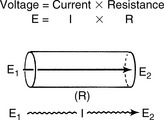
Fig. 21-2 Electrical theory. Voltage (E) is the product of current (I) and resistance (R). Voltage is the unit of potential difference in charge between two points (E1 and E2). Current flow (I) is determined by voltage and resistance within the material.

Power
Electrical power is the amount of work performed per unit of time; it is measured in watts. The rate at which the current flows (amperes [amps]) and the strength or power of flow (voltage) equals the wattage.147 The total amount of power in a circuit at any time is expressed in watts. When current flows through a conductor, a certain amount of energy is dissipated into the environment as heat or light (e.g., in a light bulb). The rate of energy dissipation is determined by resistance (R) and current (I). The power (P) generated can then be calculated.87
Relationship of Power, Current, and Resistance

Application of Terms
Electrical theory explains the properties of electrical energy or power, incorporating several important principles87:
• Flow occurs because of electrical voltage gradients (high to low).
• There must be a current source to sustain power (voltage).
• There must be a closed electrical circuit (or loop) for current flow to be possible. For example, a closed loop must be present between a sensing device and a monitor, or between a defibrillator and a patient.
The cardiovascular system functions in a manner similar to that described by the electrical principles in the preceding list. Comprehension of cardiovascular physiology requires knowledge of the properties flow (F), pressure (P), and resistance (R), and of their relationship (Fig. 21-3).
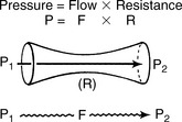
Fig. 21-3 Pressure, flow, and resistance. Ohm's law can be applied to the cardiovascular system. Pressure (P) is the product of blood flow (F) and resistance (R). Resistance is determined primarily by the radius of the vessels or chambers through which the blood flows.

There are several important similarities between electrical theory and the cardiovascular system.
• There must be a voltage (or pressure) gradient between one point in the system and another for flow to occur. The direction of flow is from an area of high electron concentration to an area of low electron concentration or from an area of high pressure to one of lower pressure.
• There must be an electron pump or current source to sustain power or voltage. In the cardiovascular system the pump is the heart.
• The system must be a closed circuit or loop if the flow is to be sustained (Fig. 21-4).
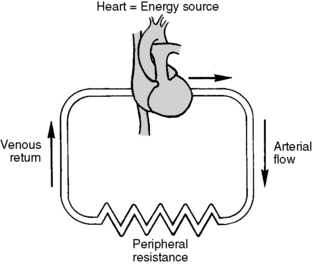
Fig. 21-4 Cardiovascular system as model similar to that occurring in a closed loop for electrical current flow. The cardiovascular system is similar to the electrical system in that it must have a power (or pressure) source (the heart). Pressure gradients must be present for blood flow to occur; blood will then flow from an area of high pressure to one of low pressure, just as current flows from an area of high electron concentration to one of low electron concentration. Finally, the system must remain a closed loop for flow to be sustained.
Power in the cardiovascular system is generated by the heart and represents the amount of work accomplished by a ventricle over a given unit of time. This power may be calculated as the stroke work index or ventricular ejection fraction.
Electrical Hazards in the Pediatric Critical Care Unit
In healthcare facilities, it is important to prevent establishment of conductive paths from patients to grounded objects.127 Conductive paths may be established though instrumentation, electrically conductive surfaces, or inadvertently. For example, damaged electrical cords can lead to possible shock or electrocution. A flexible electrical cord may be damaged by door or window edges, staples and fasteners, rolling equipment, or aging.
Hospital staff and patients can be exposed to electrical hazards that create risk of electric shock, electrocution, fires, and explosions.176 Electrical hazards are more likely when there is a lack of routine maintenance or surveillance of electrical equipment, misuse of the equipment, or a lack of understanding of the equipment and/or its controls. Oxygen-enriched atmospheres and water may also contribute to hazardous conditions.
Electric shock can produce effects that range from slight tingling to immediate cardiac arrest depending on the amount of current, the current's path through the body, the duration of contact with the current, and the frequency of the current. The risk of electrical hazard is increased as the number of instruments increases. Controlling or preventing hazards requires raising the resistance of the conductive circuit or insulating surfaces that could become energized or a combination of both approaches.127
The Electrically Sensitive Patient
Some patients are vulnerable to electrical injuries by virtue of the instrumentation used to monitor them. Patients with externalized direct conductive paths to the heart may be electrocuted at very low current levels.127 They are at risk for macroshock or microshock phenomenon.
Macroshock
Although electrical systems are typically defined by their voltage and resistance, it is current that is the dimension of physiologic significance. Current directed at the body can deliver either a macroshock or microshock depending on the route of transmission.
Macroshock refers to application of current to the outside of the body (direct skin contact). If a current is passed through a human from limb to limb, only 0.5 A (500 mA) are required to produce ventricular fibrillation. Two defenses are present to protect the body from transmission of current:
• Skin resistance in a dry state provides up to 1 million ohms of resistance. This alone would protect a person from an otherwise fatal shock when contact is made with a 120-volt line.
• Diffusion of current, which normally occurs as current passes through body tissue, reduces current density. Therefore the myocardium receives only a portion of the total current delivered to the body.
Microshock
A microshock is a small amount of current that may produce significant injury because it has a direct path of entry to the myocardium, such as through a pacemaker wire or intracardiac catheter. A microshock with as little current as 200 mA may produce ventricular fibrillation if it is directed through pacemaker wires (Table 21-1). In comparison, the threshold for ventricular fibrillation applied to the skin is documented at 500 mA or 2500 times the current required for microshock to occur. Therefore a patient with intracardiac catheters is especially vulnerable to microshock because the small amount of current required to produce fibrillation is imperceptible to the care provider.
Table 21-1 Physiologic Effects of Current Leakage
| Current | Effect with Skin Contact | Comments |
| 200 microamps (0.2 mA) |
No perception | If current contacts intracardiac catheters, it may cause ventricular fibrillation. |
| 1-10 mA (0.001-0.01 A) |
Tingling sensations | Tingling when touching an electrical device indicates an impending hazard. |
| Unplug the instrument and have it checked immediately. | ||
| 100-500 mA (0.1-0.5 A) |
“Can't let go” phenomenon | Do not touch victim or instrument. |
| Unplug device if possible. | ||
| Push the victim out of contact with the device using a broom or folded blanket or throw your body against the victim, moving him or her away from the device. | ||
| 500-1500 mA (0.5-1.5 A) |
Ventricular fibrillation | See comment for 100-500 mA. Note that these victims must receive immediate cardiopulmonary resuscitation. |
Current Leak
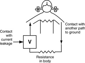
In a critical care unit setting, current leak from electrical equipment creates a major risk of macroshock or microshock. Current leak does not necessarily result from equipment malfunction, but it occurs naturally when current flows between two electrical conductors that are insulated from one another (e.g., between the internal electronics of an ECG monitor and its chassis). The current will seek a path of least resistance; if a patient is in contact with one electrical device, the current will be conducted through the patient (Fig. 21-5). Therefore, patients should be protected from contact with line-powered equipment.
Grounding
Grounding is a protective mechanism built into electrical circuits. A ground is simply a means of conducting electrical current to the earth or some other object connected to the earth. Earth has zero voltage, so the voltage drop to earth provides an inherent safety feature for grounded circuits. Current always travels along the path of least resistance, and if a connection to the ground is available it provides the path of least resistance (Fig. 21-6).
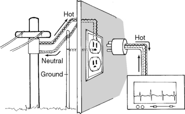
Fig. 21-6 Grounding. Current flows through a “hot” wire to the instrument and returns through a “neutral” or “cold” wire. A third “ground” wire is added as a safety mechanism and provides a low-resistance path for stray current. If there is current leak in the instrument chassis or a fracture in the neutral wire, current will flow to the ground.
There are several methods of grounding used in the critical care environment. They include circuit and system grounding, equipment grounding, and “isolated” system grounding. Circuit and system grounding are accomplished by the grounding of major power distribution transformers that service entire areas with electrical power. When an individual piece of equipment is grounded, all metal parts of the equipment are connected with a common wire to the ground.
In contrast, an isolated system commonly is created in critical care units and operating rooms. In an isolated system, grounding is provided by a special transformer, leaving the equipment “isolated” so that the current flows only from one isolated line to another (Fig. 21-7). In a perfectly isolated system, one could touch a water faucet (ground) with one hand and touch either of the two isolated lines without receiving a shock. This isolated system offers a great advantage over the power systems but is more difficult to construct.87
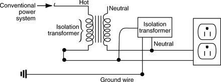
Fig. 21-7 Isolated system. An “isolated” grounding system can be created by directing current from a conventional power system into an isolation transformer. Current then enters an instrument through a “hot” wire and exits by the neutral wire to the transformer. Note that both sides of the circuit are isolated from ground. The isolation transformer represents the lowest potential in the system, so that any stray current from the instrument will flow readily to the transformer (rather than through the ground wire).
Electrical Safety
Standards for electrical safety in each hospital are based on the principles of electrical theory and current electrical code.127 Best practices include inspection and labeling of biomedical equipment when it arrives at the hospital plus routinely scheduled equipment inspections and maintenance. Daily instrument surveillance by care providers will prevent many equipment problems. Nurses should always be cognizant of potential safety hazards and they are responsible for preventative safety efforts.
1. Be alert to potential electrical hazards and inspect equipment and cords throughout the course of providing care. Use only equipment in good working condition that is labeled appropriately and inspected on schedule. All users require training before operating new or unfamiliar equipment.
Visually inspect all equipment cords and plugs and flexible cord sets before use, looking for external defects and for evidence of possible internal damage. Look for breaks in cord insulation, loose or frayed parts, broken prongs, loose plugs that fall out of the wall outlet easily, crushed outer jackets, or warning lights indicating internal malfunction.
2. Note inspection dates posted on equipment by the hospital biomedical engineers and notify the engineers of expired inspection dates. If clinical equipment is found to be damaged, it should be deenergized, tagged, and removed from the area when portable. The Safe Medical Devices Act requires reporting of medical devices believed to have caused or contributed to serious injury or death.152
3. Always use three-prong (grounded) plugs. Electricity is delivered through one of the wires in an electric cord—the live or hot wire. The other two wires are the neutral and ground wires. The ground wire is the longer round prong on the electric plug.
Unless a ground wire is present, there exists a possibility of current leak or a short circuit between the “hot” wire and the equipment housing that may cause conduction of current through the patient to another grounded source. A similar problem will occur if a two-pronged extension cord is used as an adapter between the patient monitor and the wall or if a “cheater plug” (three-pronged to two-pronged) adapter is used.
Plug three-pronged cords only into three-pronged outlets. Never remove the third prong from three-pronged cords. It is a safety feature designed to reduce the risk of shock.
4. Avoid using extension cords because they provide greater length of conduction material and the possibility of a current leak.39 Extension cords are often placed on the floor, where they may be crushed by rolling beds or machines.
Protect all cords from damage. Prevent ECG cables from becoming caught in side rails or bed mechanisms.
5. Make sure that any equipment leads connected to the patient are insulated and isolated from possible contact with stray current or a “hot” wire.
6. Do not allow any conductive liquids to come into contact with intracardiac wires (e.g., pacemaker wires) or catheters, because current leak may be conducted directly to cardiac tissue or through the heart and catheter to the grounded monitor.
7. Avoid 60-cycle (60-Hertz) interference. When two conductive surfaces (e.g., the human body and a monitor) are close to each other, they hold and transmit alternating current (AC) between them and can transmit current to other conductive surfaces. This is termed capacitance; the property of “holding” electrical energy. This capacitance between the patient and the monitor system, which is typically surrounded by other conductors (e.g., apnea monitors or IV pumps), produces a “fuzzy” baseline tracing on the ECG and can be minimized or dispersed by several methods:
8. Recognize special precautions for patients who have invasive intracardiac catheters or pacing wires. Be certain that these catheters and wires are not in direct contact with electrical equipment (e.g., ECG leads) to avoid microshock.
9. Pay particular attention to patients who are in high humidity environments (e.g., receiving humidified air via a face tent) if invasive catheters (e.g., central venous catheters) are in place. Water is an electrolyte solution that will conduct current.
10. Do not place any instruments on metal carts or shelves or near water. Water and metal are highly conductive materials that may conduct stray current.
11. Try to avoid touching both the patient and an electrical device simultaneously because you may provide a path for conduction of stray current from the device to the patient. The nurse should never touch two electrical devices simultaneously; if there is a current leak, the nurse becomes the path from the broken instrument to the ground (Fig. 21-8).
12. Minimize the effect of static electricity. Static electricity built up on the surface of an object may discharge to a person, generally resulting in a small shock. However, static electricity shocks can be much more serious in the presence of nearby flammable or combustible substances, creating the potential for explosion.
13. Always use grounded equipment. Stray current from defective equipment will follow the path of least resistance leading to ground. If your body is between a live wire and the ground, electricity will travel through you. Electric currents flow between parts of the body or through the body to a ground or the earth by whatever path possible.
14. Hospital policies regarding the use of electrical devices should be clear and accessible. Generally, biomedical departments must approve, inspect, and label all electrical items brought into the hospital (including any items that patients and families bring from home).
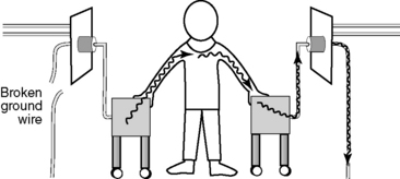
Fig. 21-8 Electrical safety. The healthcare provider should never touch two pieces of electrical equipment at the same time. If the ground wire of one unit is fractured, any stray current may flow through the provider to the other (functioning) ground wire.
All electrical equipment used in the hospital must be approved for safety by the Underwriters Laboratory (UL) or another OSHA-approved body. These approvals and inspections ensure that powered equipment meets hospital standards, is compatible with existing equipment, and that service contracts meet the needs of the hospital.131
Biomedical personnel should be familiar resources for the nursing staff. They will ensure that critical care unit equipment is safe for both patients and staff.
15. Safety signs or symbols, such as accident prevention placards, are used where necessary to warn employees about potential electrical hazards. Barricades may be necessary to prevent or limit employee or visitor access to hazardous areas.
In summary, use of high technology electrical equipment creates the potential for electrical shock hazards in the healthcare environment. Staff should be very aware of electrical safety and preventative procedures for their own protection and patient protection.
Exposure to electric shock and explosions is possible because of damaged electrical cords and the lack of routine maintenance to electrical equipment. All electrical equipment used in the hospital should be approved for safety by Underwriters Laboratory (UL) or another OSHA-approved body. Staff should be properly trained on the safe use and application of electrical equipment.