Respiratory monitoring and support

Bradley A. Kuch

Respiratory Monitoring Devices

Respiratory monitoring, particularly in combination with clinical assessment skills, is invaluable for detecting and documenting cardiopulmonary insufficiency and for guiding intervention. Ideally, such monitoring assists in the detection of cardiopulmonary insufficiency before the development of cardiopulmonary failure or arrest.

As biomedical technology continues to advance, so does the ability to monitor subtle physiologic changes in respiratory function. For these instruments to be used effectively, the clinician must be familiar with their basic principles of operation and must be able to couple use of these instruments with careful clinical observation.

Impedance Pneumography

Impedance pneumography detects chest wall movement by recording changes in resistance (impedance) across an electrical field that result from variations in thoracic volume. Chest wall impedance is measured by placing an electrode on each side of the patient's chest. Many bedside cardiac monitors include filters enabling simultaneous ECG and respiratory monitoring.45,162

When the child's respiratory rate is monitored, a high and low rate alarm must be set. In addition to high and low respiratory rate alarms, most monitors have an apnea alarm, with thresholds that can be set at 10-, 15-, or 20-second intervals. If there is a high incidence of false-positive alarms, the bedside nurse should evaluate and adjust electrode placement until placement provides maximum sensitivity to both ECG and respiratory patterns; this should reduce the number of false apnea alarms.

The most significant limitation of impedance pneumography is that all chest movement is sensed, whether or not the movement is producing effective ventilation.162 If airway obstruction develops, struggling respiratory movements will continue to be detected by the monitor, even if ventilation (air movement) is ineffective. If a child's respiratory function is poor, the nurse should not rely on this monitor to determine respiratory rate, and it should never be used to reflect effectiveness of ventilation.

Spirometry

Measurement of lung volume is accomplished by the use of spirometers. Spirometry has become more popular in the pediatric population as advancements in microprocessor technology have allowed for more accurate measurement of small lung volumes and enabled a greater variety of available bedside tests.23

Spirometry may be performed in the intubated patient if a cuffed tube is used or if there is minimal air leak around an uncuffed tube. If the patient is not intubated, a mouthpiece may be used if the child can maintain a tight mouth seal around the mouthpiece. However, patient inability to cooperate remains a significant limitation to spirometry in children less than 8   years of age. In this younger age group, patients may be unable or unwilling to make a tight seal around the mouthpiece or provide maximal effort during spirometry testing. These behaviors may result in misleading volume measurements.

A simple manometer or pressure gauge that can read both positive and negative pressures of −  150 to +  100 or +  150   mm Hg is required for these measurements. School-age children should be able to generate at least −  30 mm Hg pressure during inspiration and at least +  30   mm Hg during expiration.

In the pediatric critical care setting, spirometry may be used to measure spontaneous exhaled tidal volumes of intubated children or the vital capacity of children with restrictive lung disease. Vital capacity is defined as the maximum amount of gas that can be expired after full inspiration (deep breath) and is easily measured with a respirometer. Forced vital capacity may be measured to assess pulmonary reserve.

Other useful bedside spirometry tests include minute ventilation (tidal volume with each breath multiplied by the respiratory rate), peak expiratory flow rate, and maximum inspiratory pressure, also known as negative inspiratory force (NIF).

To measure the peak expiratory flow rate, the child is instructed to give his or her best maximum expiratory effort, exerted after a deep inhalation. A peak expiratory flow rate (PEF) is the maximum flow rate measured during forceful exhalation following a maximum inhalation. The PEF decreases when there is resistance in central airways, and it is a helpful indicator of airway constriction in patients with asthma.

The negative inspiratory force is the maximum negative pressure generated by the respiratory muscles at the patient's peak inspiratory force. It can be measured in children who are school age or older and capable of following directions. To measure the negative inspiratory pressure, the child is instructed to give his or her best maximum inspiratory effort after an exhalation to a near residual volume. Inspiratory force must be at least −  20 to −25 cm H2O (15 to 18 mm Hg) to generate a sufficient cough and clear secretions.

These volumes are presented in more detail in Chapter 9, Essential Anatomy and Physiology—Lung Volumes.

Noninvasive Transcutaneous Blood Gas Monitoring

Transcutaneous measurement of oxygen (PtcO2) and carbon dioxide (PtcCO2) tension provide the clinician with a tool for immediate and continuous assessment of tissue respiration—delivery of oxygen and removal of carbon dioxide. Transcutaneous monitoring is a noninvasive means of assessing the tissue oxygen and carbon dioxide tension, yielding more information about oxygen transport and carbon dioxide elimination than the patient's arterial oxygen tension (PaO2), pulse oximetry or cardiac index alone.

It is important to note that transcutaneous monitoring provides information regarding the gas tension of the tissue, and not the arterial blood gas tension. When the patient is hemodynamically stable, the arterial blood gas tensions and transcutaneous (tissue) measurements correlate well. However, frequently the PtcO2 is lower than the PaO2 and the PtcCO2 is slightly higher than the PaCO2.170,171 This is caused by metabolism at the tissue level consuming oxygen and producing CO2.

Instrumentation

Transcutaneous Oxygen Monitoring

The PtcO2 is measured by a heated electrode (Clark electrode) that is placed on the skin surface. The heat increases the capillary blood flow to the area, thus “arterializing” blood flow under the electrode. The sensor then measures oxygen tension at the skin surface itself; this oxygen tension should reflect the underlying tissue PO2.170,171,183 The heat ranges of the electrodes vary (most commonly between 40° C and 45° C), but the typical temperature generated is approximately 44° C.

Transcutaneous Carbon Dioxide Monitoring

Transcutaneous carbon dioxide (PtcCO2) measurements can be obtained using a pH electrode (Stow-Severinghaus electrode), infrared electrode, a mass spectrometer, or gas chromatography. To discuss each of these types of electrodes in detail is beyond the scope of this chapter. For more information regarding these electrodes, the reader is referred to Martin Tobin's Principles and Practice of Intensive Care Monitoring.171

Measurement of skin-surface or transcutaneous carbon dioxide tension (monitoring) may be a useful adjunct to the nursing care of children with acute or chronic respiratory disease. Several studies have verified high correlations between the PtcCO2 and the PaCO2 in children, with a predictable gradient between the two.21,60,76,190 Increased gradients may be caused by three of the following conditions: (1) tissue CO2 production is increased by the heat from the electrode; (2) heating the capillary blood beneath the sensor elevates the CO2 (anaerobic temperature coefficient); and (3) a countercurrent CO2 exchange mechanism in the dermal loop maintains a higher PCO2 at the tip of the loop (where the sensor lies).170,171

Consistently good correlations between PaCO2 and PtcCO2 make transcutaneous carbon dioxide monitoring a valuable tool in the pediatric critical care setting. Correlation studies have demonstrated that although the PtcCO2 will be 9 to 23   mm Hg higher than the PaCO2,98 the relationship between the two remains relatively constant. With application to an individual patient, the nurse should note the difference between PaCO2 and PtcCO2 to enable detection of trends in the patient's PaCO2. With this difference established, the number of necessary arterial blood samples is reduced, and continuous monitoring of trends in CO2 elimination are possible during procedures and changes in therapy.

The CO2 electrode is reliable even in the presence of hypotension and decreased cardiac output (i.e., shock regardless of etiology).21,22,60,76,98 Limitations of PtcCO2 monitoring include delayed measurement, inaccurate measurement, thermal injury, need for repeated calibration and site change, cost, and altered skin perfusion.

Clinical Applications

A high correlation between PaO2 and PtcO2 has been verified by many studies,34,48,101,172,175,185 particularly when the range of PaO2 is 30 to 100   torr. In fact, brief periods of hypoxemia that are reflected by a fall in PtcO2 may not be detected by intermittent PaO2 sampling. These episodes are frequently associated with nursing interventions, such as turning of the patient, vital sign measurement, dressing changes, suctioning, and chest physiotherapy.

Thick skin reduces the accuracy of the PtcO2 because fewer deep capillaries are present beneath the sensor site. In addition, thicker skin offers more resistance to oxygen diffusion than thinner skin, and it has higher oxygen consumption; thus the PtcO2 over thick skin will be lower than the PaO2. For this reason, the transcutaneous electrodes should not be applied over areas of thickened skin, such as calluses or the soles of the feet.

The PtcO2 electrode also should be placed on the trunk rather than over extremities because extremity perfusion will be influenced more readily by temperature and cardiac output. The patient should never be positioned on top of a sensor because this may decrease local blood flow.

The relationship among PtcO2, PaO2, and cardiac output have been documented in a somewhat predictive pattern: the PtcO2 correlates linearly with the PaO2 when the cardiac output is greater than 65% of normal.172,173,174,175 Tremper175 reports a high correlation between the PaO2 and PtcO2 levels when the cardiac index is greater than 1.54   L/minute per m2 BSA. If cardiac output is compromised significantly (<  65% of normal), the PtcO2 will be less than 80% of the PaO2. This poor correlation reflects a compromise in tissue perfusion and often is observed during episodes of low cardiac output or shock even before the PaO2 falls.174,175

Nursing Considerations

Erythematous marks may develop at the electrode site, resulting from heat produced by the electrodes. Although these marks may disturb the family and staff, actual blisters (second-degree burns) seldom develop if the electrodes are changed as recommended by the manufacturer.

The schedule for rotation of electrode sites on the skin surface should be strictly maintained and documented. The erythematous marks caused by an electrode may last for hours or days following electrode removal, but rarely leave scars. Many studies recommend a maximum of a 3- to 4-hour interval for each electrode location,183 but the nurse should check the manufacturer's recommendation for each electrode used.

Accurate transcutaneous monitoring requires meticulous electrode and machine calibration. The nurse should be especially aware of the following:

1. Unit calibration and skin warming time vary from 7 to 25   minutes each time the electrode is moved. The nurse should consult the device operator's manual for manufacturer's recommendations applicable to each specific unit.

2. The correlation between PaO2 and PtcO2 should be determined if changes in the patient's clinical condition are observed.

3. The electrodes must be replaced and moved to a new location on the child's trunk or extremities at regular intervals to avoid skin irritation and compromise in electrode performance from heat-induced edema or other tissue changes at the electrode site. Microelectrodes heated to 44° C may require changing only every 6   hours, whereas large cathode electrodes require repositioning every 2 to 3 hours (check manufacturer's recommendations).

4. The nurse should recognize electrical drift and/or other sources of machine error.

5. Alarm systems (for low or high PtcO2) should be established and verified at regular intervals.

6. The procedures for troubleshooting problems with the monitor should be available in the unit.

In some hospital units, nurses are required to obtain an arterial sample for blood gas analysis after every electrode change, to compare the child's arterial blood gas values with transcutaneous values. As noted, the nurse must be knowledgeable about the procedure for machine calibration and maintenance (consult operator's manual and unit protocols) and must also be able to recognize electrical drift and/or mechanical error.

Maintenance should include frequent observation of the fluid space in the sensor. Gain or loss of fluid results in an erroneous PtcCO2 measurement. Each nurse must be familiar with interpretation of measurements, procedures for troubleshooting, and setting of alarm systems.

Noninvasive Blood Gas Monitoring: Pulse Oximetry

Oxygen saturation of hemoglobin (oxyhemoglobin saturation) in arterial blood may be monitored continuously using a pulse oximeter. The pulse oximeter is the monitor of choice for noninvasive monitoring of oxygenation, and the accuracy of these monitors has been demonstrated in children over a wide range of clinical conditions.29,42,136,157,158,159 The response time of the oximeter is shorter than that of the transcutaneous oxygen monitors. The oximeter does not require calibration, and there are virtually no risks to the patient.

Mode of Operation

An instrument probe, housed in a clip or on an adhesive strip, may be placed on the finger, toe, foot, hand, or ear lobe. In the probe are two light-emitting diodes that emit red and infrared light through the tissue to a photodetector (Fig. 21-31). The red light absorption will be inversely related to the amount of saturated hemoglobin (i.e., hemoglobin that is bound to oxygen) passing through the tissue. Well saturated hemoglobin absorbs little red light and desaturated hemoglobin (i.e., hemoglobin not bound to oxygen) absorbs a large amount of red light.

image

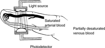
Fig. 21-31 Pulse oximeter. Two light-emitting diodes (light sources) transmit a red and an infrared light through the pulsatile tissue bed. The photodetector must be placed directly across the pulsatile tissue bed from the light source. Oxygenated (saturated) and deoxygenated (desaturated) hemoglobin absorb red and infrared light differently, and the hemoglobin saturation (percent of total hemoglobin that is oxygenated) is related inversely to the amount of red light absorbed.

Because the probe is placed over a pulsatile tissue bed, the pulse oximeter unit computes a pulse rate, and can signal the strength of the pulse. However, patient movement can produce artifact that significantly affects the accuracy of the pulse measurement. A difference between the pulse rate displayed by the pulse oximeter and the heart rate detected by the cardiac monitor should prompt an immediate evaluation of the patient and the patient's systemic perfusion.

Pulse oximeters require pulsatile blood flow to operate properly. These monitors generally provide accurate results over a wide range of clinical conditions (including hypotension, low cardiac output, and hypothermia).29,42,72,100,157,173,177,183 However, the response time in the presence of hypoxemia varies widely from instrument to instrument. Some units may fail to reflect acute, severe hypoxemia and may overestimate the hemoglobin saturation. This tendency may be observed more frequently with finger probes than with ear probes.100,158

Most oximeters provide a low signal alert, which may indicate diminished pulse intensity under the probe. Accuracy of the measured O2 saturation is not necessarily altered by low pulse intensity,100 but the low signal alert should prompt evaluation of the patient and the patient's systemic perfusion.

The pulse oximeter may be a useful adjunct to cardiovascular monitoring. It enables monitoring of the pulse in an ischemic limb and reflects changes in pulse rate in unstable patients and in patients during pacemaker support.

Pulse oximeters are not reliable in the presence of methemoglobinemia and carbon monoxide poisoning, because the effect of these hemoglobins on light absorption is not factored into the calculation of hemoglobin saturation. As a result, when these conditions are present, the pulse oximeter will display a falsely high hemoglobin saturation, reflecting only the percent saturation of the child's normal hemoglobin, rather than the saturation of the child's total hemoglobin.

Troubleshooting During Pulse Oximetry

Several operator-controlled variables may cause a poor signal (and resulting alarm), including the presence of ambient light and movement artifact. To eliminate ambient light, the monitored area can be wrapped loosely with an opaque material such as gauze. The nail bed should be clean before sensor application.36,77,189

Movement artifact is difficult to control in pediatric patients. Ear clip sensors are often the least likely to be disturbed with movement. However, if movement artifact is a significant problem the oximeter may be placed on a restrained extremity. In addition, application of a disposable sensor on the hand or foot may result in less movement artifact than that occurring with placement over a finger or toe. Occasionally, the patient may require sedation (with physician input and order).

Neonatal studies suggest that attachment of the probe to the patient before it is attached to the device may shorten the time required to obtain an initial signal.132 The nurse must be familiar with the rapidity of signal response required for the pulse oximetry devices used in the critical care unit.

Noninvasive Capnometry: End-Tidal Carbon Dioxide Monitoring (PETCO2)

Instrumentation

The exhaled carbon dioxide is the tension (in mm Hg) or partial pressure of carbon dioxide in expired (exhaled) gas. The highest exhaled carbon dioxide tension is present at the end of the expiration; this end-tidal CO2 or PETCO2 is also known as the end-expiratory CO2. The PETCO2 normally trends with the patient's arterial carbon dioxide tension.

The continuous measurement of the PETCO2 by infrared spectroscopy is called capnometry. Capnography includes a display (graph) of the waveform of the carbon dioxide tension throughout inspiration and exhalation and the monitor typically provides a digital display of the PETCO2. Analysis of the capnogram is discussed in the section that follows (see Clinical Applications of Capnography).

End-tidal CO2 monitors can now be purchased as part of a mechanical ventilation system or as separate monitors. Capnometry can also be performed via nasal cannula during spontaneous breathing.170a

The infrared CO2 analyzer consists of three components: an inferred radiation source, a gas sampling chamber, and a detector. Carbon dioxide absorbs infrared radiation of specific wavelengths, so as the infrared rays are passed through expiratory gas, a detector then registers the intensity of the radiation in the gas (and conversely, the absorption of infrared radiation) to determine the tension or partial pressure of CO2.171 This analyzer therefore enables evaluation of alveolar ventilation and CO2 elimination.

Two types of PETCO2 monitoring methods are used clinically—mainstream and sidestream analyzers. In mainstream analyzers the detector module is placed in the ventilator circuit at the proximal end of the endotracheal tube, in line with the expired gas flow; this placement allows for rapid response to changes in PETCO2. However, the mainstream module can be affected easily by condensation and mucus, and requires frequent cleaning of the sensor module.

In sidestream modules a low flow (50 to 150   mL per minute) vacuum aspirates a small sample of expired gas to the analysis module located in the monitor. This sampling method is also affected by condensation and mucus, which can occlude the sampling line. Sidestream technology has also been found to be relatively inaccurate at small tidal volumes, increased I:E ratios, and high resistance states.95,106

The presence (but not the tension) of CO2 in exhaled gas can be detected through use of a colorimetric device attached to the proximal end of an endotracheal tube (or between an endotracheal tube and a resuscitation bag or mechanical ventilation system). Colorimetric CO2 detection devices change color (typically from purple to yellow, but the color change may vary from device to device) when CO2 is present in the gas flowing through the device. Typically the color change develops within about 6 breaths, and the color will change permanently after several minutes or hours of use. These devices are considered qualitative (i.e., indicating presence or absence of CO2) rather than quantitative devices, and are not discussed further in this chapter (see Chapter 9 for additional information).

Clinical Applications of Capnography

The correct use of a PETCO2 device requires an understanding of the patient's alveolar-arterial (A-a) CO2 gradient. In addition, the PETCO2 must be evaluated in conjunction with the clinical examination.

Relationship Between Arterial and End-Tidal CO2 Tension

Normally there is no significant difference between arterial and alveolar (or end-tidal) CO2 tension, because carbon dioxide in pulmonary capillaries normally diffuses freely into the alveoli to be exhaled and measured as PETCO2. Thus, the normal difference between the PETCO2 and the arterial CO2 tension is 2 to 5   mm Hg or less.165,183 This small difference results from mixing of CO2-containing alveolar gas with exhaled gas devoid of CO2 from anatomic dead space. This high correlation has been documented even in neonates,120 particularly if they receive muscle relaxants during mechanical ventilation.

The PETCO2 will be nearly identical to the patient's arterial CO2 tension (PaCO2) only if there is a normal (very low) alveolar-arterial carbon dioxide (A-aCO2) gradient and no alveolar dead space. If a large A-aCO2 gradient or a large amount of alveolar dead space is present, the PETCO2 will not equal the PaCO2. For example, if there is impairment of CO2 diffusion from the blood into the alveoli, such as in the neonate with respiratory distress syndrome or the child with acute respiratory distress syndrome,120,183 the difference between the PETCO2 and the arterial CO2 tension increases. However, changes in the PETCO2 accurately reflect trends in the child's PaCO2, even if a significant lung disease is present.

Any time the PaCO2-to-PETCO2 gradient increases, dead space ventilation has increased. Increased dead space ventilation occurs any time pulmonary perfusion decreases relative to alveolar ventilation. Conditions causing increased dead space ventilation include pulmonary vascular disease or increased pulmonary vascular resistance, pulmonary embolus, decreased right ventricular output (e.g., shock or cardiac arrest), and excessive PEEP. A sudden decrease in the PETCO2 to zero could indicate extubation, ETT obstruction, esophageal intubation, or a disruption or leak in the system

The PETCO2 will not correlate with the PaCO2 if the child is breathing rapidly and shallowly or hyperpnea is present. Such alterations in respiratory patterns will result in sampling error and poor correlation between PETCO2 and PaCO2.95,106,171

Analysis of Capnograph

The waveform that is displayed by variations in exhaled CO2 throughout the respiratory cycle is known as a capnogram. To use the capnogram, the clinician must first be familiar with a normal PETCO2 waveform (Fig. 21-32).183

image

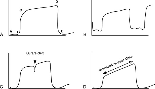
Fig. 21-32 Capnogram phases. A, Normal capnogram illustrating each phase of exhalation (see text, Analysis of Capnograph). B, Rebreathing capnogram: Inspiratory level does not return to zero. C, Curare cleft: Cleft in the alveolar plateau indicates a return of diaphragmatic activity in a patient receiving neuromuscular blockade. D, Increased alveolar plateau slope is representative of small airway obstruction (e.g., asthma, bronchiolitis).

A capnogram is divided into four phases. Phase A-B is the inspiratory cycle, when no carbon dioxide is detected. Phase B-C is the beginning of exhalation (emptying of dead space and alveolar gas), at which point carbon dioxide tension rapidly increases.183 Phase C-D reflects exhalation of predominantly alveolar gas, and is also known as the “alveolar plateau.” Point D is the “end-tidal” point at which carbon dioxide exhalation is at its maximum level (i.e., the PETCO2). Phase D-E is the beginning of inspiration (inhalation of CO2 free gas) where the waveform returns to zero.

Evaluation of Changes in PETCO2.

Analysis of the capnogram and trends in the PETCO2 may enable detection of improvement or deterioration in ventilation, increase in dead space, a fall in cardiac output and ET tube displacement. It can enable detection of an obstructed airway, and/or the return of diaphragm function in the paralyzed patient.183 If the PETCO2 and the PaCO2 fall together, the patient's ventilation has improved; if both rise, the patient's ventilation is reduced.

As noted, if the PETCO2 falls and the PaCO2 rises, dead space has been added to the system (areas are ventilated thats are not perfused). This condition can develop if the lung is overdistended with PEEP. The PETCO2 can fall without a rise in the PaCO2 when cardiac output falls, and pulmonary blood flow and delivery of CO2 to the lungs decreases. The PETCO2 will fall to near zero with spontaneous extubation. For additional information about PETCO2 monitoring in the child with pulmonary disorders, see Chapter 9.

Recently capnography has been used to monitor resuscitation quality during cardiac arrest in intubated patients. When cardiac output is very low during attempted resuscitation, little blood flow is delivered to the lungs, so little carbon dioxide is detected in exhaled gases. When blood flow improves during attempted resuscitation, blood flow to the lungs improves and the PETCO2 rises. The PETCO2 rises abruptly when there is return of spontaneous circulation (see Chapter 6).

Nursing Considerations

When capnometry is in use, the nurse must be able to calibrate the instrument and must be aware of the relationship between the patient's alveolar (or end-tidal) and arterial CO2 tensions. The nurse must be able to correlate PETCO2 values with the clinical status of the patient and must be aware of sources of instrument error.

The absolute PETCO2 at any one time is usually not as important as the trends documented by this equipment, although a sudden fall in PETCO2 in an intubated patient should prompt immediate suspicion of spontaneous extubation (see Fig. 9-21). The PETCO2 should be compared with either a venous or arterial PCO2 to ensure that the two correlate. In addition, it is critical to verify effectiveness of oxygenation and ventilation through careful clinical assesment.183

Invasive Arterial Oximetry

Arterial oximetry is an invasive method of continuously monitoring arterial oxygen saturation. This method of oximetry uses an intraarterial electrode threaded through to the tip of an arterial catheter.

Clinical trials have demonstrated the accuracy of the polarographic electrode, although a high incidence of electrode failure has been reported.55 LeSoeuf 101 reported moderately high correlations between the indwelling oximeter and the oxyhemoglobin saturation reported by a PtcO2-measuring device. However, the arterial oximetry was not compared with oxygen saturation measured by direct blood sampling and measurement using a co-oximeter.

Clinical Applications

Arterial oximetry allows direct, continuous measurement of oxygen saturation, which is preferable to intermittent measurement. The indwelling electrode does not require frequent repositioning (e.g., as is necessary with transcutaneous oxygen monitoring).

The disadvantages of arterial oximetry are related to vascular effects of a foreign body and the potential for inaccurate results. The catheter may lodge against the arterial wall, producing arterial spasm. Fibrin clots may form at the catheter tip, resulting in inaccurate readings and risk of embolism. Hemodilution (particularly a hematocrit <  30%) may result in erroneous oxygen saturation calculations. Finally, electrode failure has been reported.

Use of the arterial oximeter may be limited in pediatric patients because they have small vessel size. The risks of infection, thromboembolic events, and other potential complications of the indwelling arterial oximeter have not been documented in pediatric patients. Currently, arterial oximetry is not performed frequently in children because further research is required to verify its effectiveness.

Invasive Mixed Venous Oxygen Saturation Monitoring

Continuous monitoring of mixed venous oxygen saturation (SvO2) in pediatric patients is possible with a fiberoptic pulmonary artery catheter. The central venous oxygen saturation (SCVO2), typically obtained from the superior vena cava, approximates the mixed venous oxygen saturation (typically the SCVO2 is about 2% to 3% higher than the SvO2), and is often used as a surrogate for the mixed venous oxygen saturation. The SCVO2 can be monitored with a fiberoptic central venous catheter.

Changes in the SvO2 (and SCVO2) may reflect alterations in cardiac output, oxygen delivery, hemoglobin, or changes in oxygen consumption. In some instances, oxygen demands are changing continually (as with sepsis), and continuous SvO2 (SCVO2) monitoring may provide an early indication of decreased oxygen delivery, increased oxygen demand or decreased oxygen utilization.

Description

The SvO2 can be monitored with a fiberoptic 5-French, 5-lumen balloon-tipped pulmonary artery catheter that also enables measurement of pulmonary artery pressure, central venous pressure, and pulmonary wedge pressure, and for thermodilution cardiac output calculations.

Continuous monitoring of SCVO2 is performed using a fiberoptic central venous catheter. Pediatric central venous oximetry catheters are available in 4.5 and 5.5-Fr sizes and three different lengths (Edwards PediaSat, Edwards Lifesciences, Irvine, CA).110a

The hemoglobin saturation is determined by spectrophotometric reflection. The catheter port used for SvO2 monitoring is connected to an optical module, which transmits a narrow band width (wavelength) of light to the tip of the fiberoptic catheter. This light will be reflected by saturated (oxygenated) hemoglobin differently than by desaturated hemoglobin (i.e., hemoglobin not bound to oxygen).

The light emitted by the catheter is reflected by the hemoglobin and transmitted back via a separate fiberoptic filament to the module (Fig. 21-33). The microprocessor analyzes the amount of light transmitted and reflected and averages the signal over 2 to 3 seconds. A tandem recorder trends the SvO2 on a graph recording. A light intensity indicator (at the tip of the catheter) is also recorded and monitored; changes in the light intensity may indicate a change in catheter position, inadequate blood flow, or damage to the fiber optics.19,62,81

image

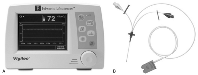
Fig. 21-33 A, Continuous central venous oxygen saturation (SCVO2) microprocessor/monitor and B, multilumen central venous catheter. The fiberoptic catheter contains filaments that transmit red light to and from the blood. The light is reflected by circulating hemoglobin and transmitted via a second optical fiber to the microprocessor, where the hemoglobin saturation is determined. Catheters are available in 3 lengths. (Vigileo monitor and PediaSat catheter photograph courtesy of Edwards Lifesciences, Irvine, California.)

Two different reflection spectrophotometry processor units are available: a three-wavelength and a two-wavelength device. The three reference wavelength processor is thought to be more accurate over a wide range of physiologic conditions, particularly changes in hemoglobin concentration. When a device with two reference wavelengths is used, the hemoglobin concentration must be entered whenever it changes55 (typically this calibration is performed at regular intervals, based on institutional protocol and manufacturer's recommendations). The bedside team must familiarize themselves with published experience of the device in use to be aware of accuracy of the device and potential drift.55,110a,187

Operation

Unit calibration is recommended before insertion of the catheter. This calibration is performed using the catheter, the processor, and a standard optical reference provided with the catheter. If the SvO2 monitor is part of a pulmonary artery catheter, the appropriate pressure transducers also must be calibrated and connected to their respective monitoring systems and catheter ports before the catheter is placed.

Insertion into the central vein is accomplished using a standard Seldinger technique. Pressure waveforms and SvO2 readings are monitored during insertion to guide catheter placement.

If the fiberoptic is contained in a pulmonary artery catheter, placement is correct when the pulmonary catheter is correctly positioned. If the tip of the pulmonary artery catheter is advanced too far into a pulmonary artery, a falsely high SvO2 will be calculated, reflecting the proximity of the fiberoptic to blood that is oxygenated by surrounding alveoli.154

Recalibration after insertion should be performed according to manufacturer's recommendation: a mixed venous blood sample is sent for laboratory measurement of the oxygen saturation using a co-oximeter (i.e., not a calculated saturation). Simultaneous with the blood sampling, the nurse should document the mixed venous oxygen saturation displayed by the device. Once the laboratory analysis of the blood sample is complete, the device should be recalibrated based on the laboratory measurement.

Clinical Applications

The normal mixed venous oxygen saturation is usually between 65% and 75%. A rise in SvO2 reflects one of four conditions: (1) increased oxygen delivery, caused by a rise in cardiac output, or an increase in arterial oxygen content; (2) reduced oxygen consumption, as observed with hypothermia, neuromuscular blockade, and anesthesia; (3) the presence of a left-to-right intracardiac shunt; or (4) mechanical interference from the measuring unit (e.g., a wedged catheter).

The SvO2 may fall for the following reasons: (1) decreased oxygen delivery, resulting from decreased cardiac output, hypoxemia associated with pulmonary dysfunction, or anemia, or (2) increased oxygen consumption caused by shivering, seizures, hyperthermia, sepsis, or agitation. The SvO2 will track with changes in cardiac output, but there are other factors, such as oxygen demand and oxygenation of blood in the lungs, that influence the SvO2.

The SvO2-monitoring system has been used in adult patients since 1981, and its efficacy has been documented in a variety of physiologic conditions.19,55,62,81,93,122,146,154,187 The enthusiasm for its use in adult patients is based on its accuracy and reliability as well as its ability to reflect changes in cardiac output and arterial oxygenation instantly and continuously.

The use of venous fiberoptic oximetric catheters has been successful in the management of pediatric patients following surgery for congenital heart disease and for pediatric patients with septic shock. Muller and co-workers described the use of a 2-French fiberoptic probe that is introduced through a single-lumen central venous catheter in a series of three infants who underwent a stage 1 Norwood procedure.126 The fiberoptic probe was inserted approximately 2.5   cm beyond the central venous catheter tip, allowing for continuous central venous oximetry (SCVO2). The group found good correlation between the fiberoptic SCVO2 and laboratory SvO2 evaluated by co-oximeter (r = 0.912. 95% CI: 0.716-0.975).126 However, they reported that the fiberoptic probe was less accurate in conditions of very low saturation (<  40%).

More recently, de Oliveira reported that goal-directed resuscitation using the end point of a superior vena caval oxygen saturation (ScvO2) ≥  70% significantly improved the outcome of pediatric patients with septic shock (28-day mortality 11.8% vs. 39.2%).43 Since 2006, pediatric SCVO2 catheters have been approved by the Food and Drug Administration for use in children in the United States.

Disadvantages

Changes in the calculated SvO2 (or SCVO2—in this section they are used interchangeably) are not always indicative of changes in patient condition. The high incidence of artifact during continuous SvO2 monitoring seems to be linked to the fact that SvO2 determination is dependent on reflected light. As rapid blood flow passes the catheter tip, consistent light reflection may not occur. Faulty connections, fiberoptic fracture, occlusion of the catheter tip by emboli, and wedging of the tip against the vessel wall also may produce inaccurate SvO2 readings.122,154

Whenever a fall in SvO2 is noted, the patient's oxygenation and systemic perfusion must be assessed. Clinical evaluation always should be used to confirm any changes associated with deterioration in the SvO2. The function of the monitor should be assessed only after the patient's condition is evaluated.

Factors reducing the accuracy of fiberoptic SvO2 monitoring include lack of in-vitro and in vivo calibration, lack of intensity calibration during insertion, bent or broken optics, catheter tip close to or facing the vessel wall, increased carboxyhemoglobin or methemoglobin, and extreme hypoxemia (<  40%).171

The limited variety of available sizes of the fiberoptic catheters prevents its use in very small children. Although the 2- to 4-French SvO2 fiberoptic catheter can be used in infants and for central vein oximetry, these small fiberoptic catheters do not enable other hemodynamic measurements and calculations (e.g., CO, PAWP, vascular resistances) that are possible with a pulmonary artery catheter with fiberoptic and thermistor. With the availability of the pediatric fiberoptic central venous catheter more experience is being gained with continuous monitoring of central venous oxygen saturation as a surrogate for the mixed venous oxygen saturation in critically ill children.110a More data about its reliability and effectiveness is anticipated.

Esophageal Pressure Monitoring

Esophageal pressure (Pes) monitoring provides important information regarding intrathoracic pressure during mechanical ventilation. It yields an indirect measurement of pleural pressure, providing information regarding the distending pressure of the lung and chest wall. Evaluation of Pes also allows for division of the respiratory system's resistance and compliance into pulmonary and chest wall components.

A change in Pes (ΔPes) as well as Pes swings reflect the level of patient effort during spontaneous and supported mechanical breaths; these values can be used to calculate the work of breathing imposed by the lung and ventilator circuit. The Pes may also be useful in determining optimal PEEP in patients with acute lung injury/acute respiratory distress syndrome (ALI/ARDS).

In a randomized controlled trial, Talmor and colleagues reported that a “ventilator strategy using esophageal pressures to estimate the transpulmonary pressure significantly improves oxygenation and compliance” in patients with ALI/ARDS.20,166 They demonstrated improved PaO2:FiO2 ratios, respiratory system compliance, and dead space to tidal volume ratio (Vd/Vt) when the PEEP was set to keep the transpulmonary pressure greater than 0   cm H2O guided by Pes monitoring.20,166

Instrumentation

Esophageal pressure is measured using an air-containing balloon that is sealed in a catheter connected to a pressure transducer. The catheter is inserted into the thoracic esophagus. A change in pressure imposed on the balloon is conveyed via the catheter to the pressure transducer, and the pressure is displayed on the monitor or ventilator.

Catheter dimensions range from an internal diameter of 1 to 1.2   mm (for use in newborns and smaller children) to an internal diameter of 1.4 to 1.7   mm (for use in large children and adults). Adequate balloon volume is essential for accurate detection of the Pes.20,171 Typically, a balloon volume of 0.5   mL is sufficient; however, the range of gas volume should be determined from the catheter packaging; the packaging indicates the clinical situations in which more or less volume may be indicated.171

The balloon is positioned by passing an empty balloon catheter into the stomach via the nares or mouth. A volume of 0.5   mL of air is then injected into the system and the catheter is attached to the pressure transducer.171 A positive pressure swing indicates that the balloon is in the stomach. The catheter is then withdrawn until a negative pressure deflection is identified on the monitor, indicating the balloon is in the thoracic esophagus. The catheter is then pulled back an additional 5 to 10   cm, which positions the entire balloon in the esophagus.

The final position of the balloon in the mid- and lower esophagus can be verified by chest radiograph.20 Correct position of the balloon can be validated by using the “occlusion test,” which is accomplished by having the patient take a spontaneous breath against a closed airway while observing the ΔPes and change of pressure at the airway opening (ΔPAO).171 If the balloon is in correct position, the clinician will find near unity between the ΔPes and ΔPAO throughout the inspiratory cycle.171

Clinical Applications

Esophageal pressure monitoring has a wide range of clinical applications. As noted, Pes is beneficial in determining the patient's work of breathing imposed by underlying lung disease and the addition of the ventilator circuit. Evaluation of the work of breathing allows adjustment of mechanical support to decrease the patient's metabolic demands and/or identify if the patient is ready for extubation.

In addition to work of breathing assessment, Pes monitoring provides information regarding respiratory muscle function. More specifically, monitoring of the Pes in conjunction with gastric pressure monitoring enables calculation of diaphragm force-generation, relatively isolated from intercostal and other accessory muscles, and from elastic recoil of the chest wall. Some authors have suggested that isolated diaphragm function should be assessed using Pes measurement in patients with suspected diaphragm weakness or paralysis.20

Esophageal pressure measurement may be beneficial in any clinical situation characterized by decreased lung compliance.20,166,171 If poor respiratory system compliance is determined to be caused by chest wall edema, low lung compliance, or abdominal compartment syndrome, the clinician may be better able to titrate PEEP without causing lung trauma.

Nursing Considerations

The bedside nurse must be able to assess the catheter position and document depth and position at the insertion location, as well as Pes measurements. The catheter must be secured at the nares without causing tissue breakdown around the nares or mouth.

Oxygen Administration Systems

Supplementary oxygen is commonly used in the pediatric critical care unit. Although oxygen may be administered in a variety of ways, it must always be treated as a drug, with accurate administration and documentation of the dose and careful assessment and documentation of patient response.

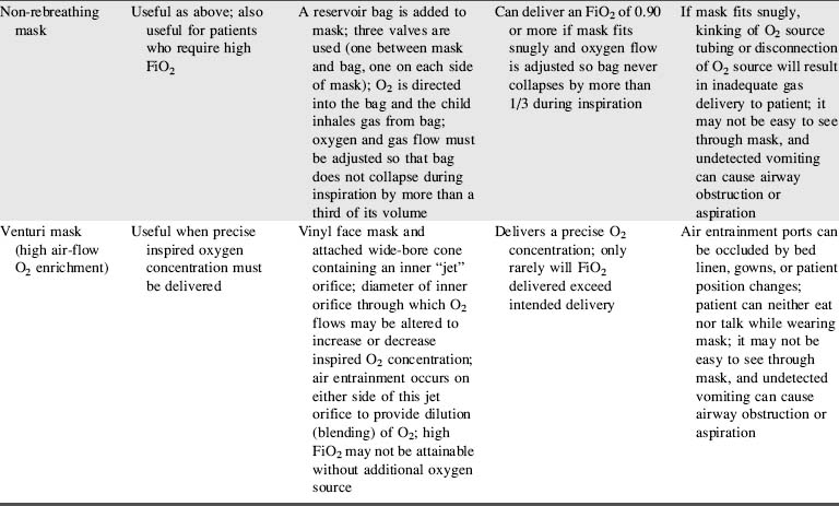
The appropriate device for delivery of supplementary oxygen is determined by the patient's age, size, and inspiratory flow rate (tidal volume in mL/sec), and the fraction of inspired oxygen (FiO2) needed. The method for estimation of inspiratory flow rate is summarized in Box 21-1. Oxygen delivery devices can be divided into two classes: variable-performance oxygen delivery devices (low flow devices) and fixed-performance oxygen delivery devices (high-flow devices).

Box 21-1 General Principles for Estimation of Required Oxygen Inspiratory Flow Rate

1. 60   seconds/min ÷ respiratory rate = time of one respiratory cycle in seconds (s)

2. Multiply time of one respiratory cycle (in seconds) × inspiratory fraction (the portion of the respiratory cycle required for inspiration—typically 0.5, but may be 0.3 in children with asthma and long exhalation) = inspiratory time (in second[s])

3. Divide tidal volume (VT) in mL (typically 4-6   mL/kg) per breath by the inspiratory time (in seconds) = inspiratory flow in mL/s

Note: For convenience, multiply inspiratory flow in mL/s by 60   s/min to compare with gas flow rate in mL/min (and divide mL/min by 1000 to obtain L/min to compare to gas flow rate)

Examples

Example 1: 4 kg Infant

Would a 2   L/min oxygen flow through nasal cannula provide high or low flow and low FiO2 for a 4   kg infant?

The infant's normal Vt is 20   mL (using 5   mL/kg). This example uses a typical respiratory rate of 60/min with an inspiratory portion of 0.5/breath.

1. 60   s/min ÷ 60/min = respiratory cycle of 1   s

2. 1   s × 0.5 = 0.5   s/breath

3. 20   mL/breath ÷ 0.5   s = 40   mL/s inspiratory flow (× 60   s/min = 2400   mL/min = 2.4   L/min)

A nasal cannula delivering a flow of 2   L/min gives a flow rate that would almost meet the inspired flow rate of a 4   kg infant, and thus the infant's inspired FiO2 would be fairly high.

Example 2: 20 kg preschooler

Would a 2   L/min oxygen flow through nasal cannula provide relatively high or low flow and low FiO2 for a 20   kg preschooler?

A 4   year old, 20   kg child's normal tidal volume (VT) is 100   mL.

1. 60   s/min ÷ 30/min = respiratory cycle of 2   s

2. 2   s × 0.35 = 0.7   s inspiratory time

3. 100   mL/breath ÷ 0.7   s = 142   mL/s (× 60   s/min = 8571   mL/min = 8.6   L/min)

The preschooler is breathing at a slower rate than the infant, so the preschooler's inspiratory time is slightly longer (here estimated at 0.7   s for each breath). Mean inspiratory flow rate is ~  142   mL/s or 8571   mL/min (8.6   L/min), well higher than the delivered oxygen flow 2   L/min. The preschooler will entrain much more room air so the inspired FiO2 is low.

Courtesy of Mary Fran Hazinski, Arno Zaritsky, and Stephen S. Schexnayder.

Low flow (variable-performance) devices are unable to deliver an oxygen flow rate sufficient to supply the patient's inspiratory flow rate. As a result, when the child inspires, room air is entrained with the supplementary oxygen and the FiO2 varies with the patient's respiratory rate and tidal volume.183

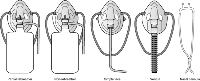
High flow (fixed-performance devices) can deliver an oxygen flow rate that meets or exceeds the patient's inspiratory flow rate. As a result, a high FiO2 can be consistently delivered. Fig. 21-34 and Table   21-9 describe types of oxygen delivery systems and their advantages and disadvantages.

image

Fig. 21-34 Oxygen administration systems.

Table 21-9 Oxygen Delivery Systems

image

image

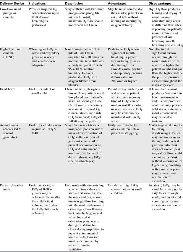
The nurse caring for the child receiving supplementary oxygen must monitor and record the type of oxygen delivery device, the set liter flow (in liters per minute), the FiO2, and the child's response to therapy.

Nursing Considerations

The bedside nurse should assess the patient and the oxygen delivery system:

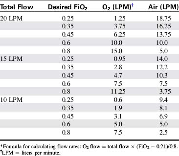
1. Analyze the fraction of inspired oxygen (FiO2) frequently—many hospitals require continuous or hourly analysis. If O2 drift is a problem, continuous analysis of the inspired oxygen concentration is usually indicated. Table   21-10 provides a formula for calculation of inspired oxygen concentrations.

2. Monitor patient oxygenation through pulse oximetry and, as needed, obtain an arterial blood gas analysis (the gold standard) to evaluate effectiveness of oxygen therapy. The nurse and the physician should determine the desired frequency of blood gas analysis. Invasive or noninvasive evaluation of oxygenation should be performed 15 to 20   minutes after any change in FiO2.

3. Observe for changes in respiratory rate, effort, and/or skin color of the patient with any changes to the oxygen delivery device or FiO2. Document these observations and notify the physician or on-call provider of any clinical changes.

4. Ensure that the inspired oxygen is humidified and warmed unless otherwise directed by the physician or on-call provider.

5. Ensure that any tubing in the O2 delivery system is changed daily to minimize the risk of tubing contamination and healthcare acquired infection.

6. Keep infants and children dry when humidified oxygen is provided by head hood or face tent. Frequent clothing and linen changes may be necessary. Monitor the child's temperature closely if heated or cooled aerosol is used.

7. Assess for potential complications of oxygen therapy.28,183

a. Respiratory depression may occasionally occur in some children with chronic lung disease, specifically if the child's respiratory drive occurs as a result of hypoxia rather than hypercarbia.
b. Absorption atelectasis may develop if an inspired oxygen concentration of 100% (FiO2 of 1.00) is administered for extended periods of time. If the alveoli become filled with oxygen, alveolar nitrogen subsequently is washed out. As oxygen is absorbed from the alveoli, atelectasis can develop.28,183
c. Substernal pain may develop in patients who receive high inspired oxygen concentration. The mechanism is not well understood but may be related to tracheitis.28
d. Oxygen toxicity can result from high inspired oxygen concentrations (FiO2 greater than 0.6), particularly if coupled with positive pressure ventilation. It can produce endothelial and alveolar epithelial damage that may produce fibrotic scarring and chronic lung disease. Inspired oxygen concentrations and the duration of oxygen exposure associated with oxygen toxicity have not been established. Individual susceptibility makes it impossible to determine safe or toxic levels of oxygen support. Therefore the child with respiratory distress should receive only as much supplementary oxygen as is needed to ensure satisfactory oxygen delivery. Inadequate or excessive inspired oxygen concentration must be avoided.
e. Retinopathy of prematurity (ROP) occurs predominantly in extremely premature neonates. In its most severe form, ROP may progress to retrolental fibroplasia (RLF) with retinal detachment and blindness. The etiology of ROP is complex and still poorly understood. Factors such as respiratory failure, hypoxia, hypercarbia, inadequate nutrition, extreme prematurity, and high levels of inspired oxygen have been implicated. In the modern era, severe ROP is rare in infants beyond 30   weeks gestation.28,183

Table 21-10 Examples of Oxygen and Air Flow Rates * Required to Blend Specific Inspired Oxygen Concentrations

image

Mechanical Ventilation

Assisted ventilation is indicated for patients who are unable to maintain adequate oxygenation or eliminate carbon dioxide, or who develop refractory circulatory failure. These patients generally exhibit clinical signs of respiratory failure or shock.

Mechanical ventilation is based on the properties of normal pulmonary function. During inspiration, alveolar pressure must be significantly lower (normal breathing or negative pressure ventilation) or greater (positive pressure ventilation) than atmospheric pressure. This is accomplished in two ways:

(1) By making atmospheric pressure or pressure surrounding the chest more negative

(2) By increasing alveolar pressure via delivery of gas under positive pressure.

These inspiratory mechanisms describe the two major forms of mechanical ventilatory assistance: negative pressure ventilation and positive pressure ventilation.

Negative Pressure Ventilation

Negative pressure ventilation is a relatively uncommon mode of ventilatory support that creates a negative (with respect to airway opening pressure) extrathoracic pressure, so the child's chest expands, causing inspiration. Because negative pressure ventilation is provided without the need for insertion of an artificial airway (e.g., endotracheal tube), it is a form of noninvasive ventilation.

Description

A tank or shell surrounds the thorax; negative pressure is created around the thorax by a vacuum. The negative pressure “pulls” the thoracic cage outward, thereby increasing intrathoracic volume and reducing intrathoracic pressure. A pressure gradient is then present between the mouth and the intrathoracic space (where the pressure is now approximately −  10 to −  15 cm H2O), so air flows into the alveoli. Exhalation occurs passively when the vacuum cycles off.183

In order to generate the subatmospheric pressure around the thorax, the shell must seal around the arms, neck and lower abdomen. This required proper fit. If diapers are used, they should be secured outside (below) the shell.

Clinical Applications

Negative pressure ventilation may be used for support of children with chronic respiratory failure secondary to neuromuscular disease, such as the child with phrenic nerve injury or muscular dystrophy. The child's lung tissue must allow normal gas diffusion (i.e., pulmonary interstitial disease cannot be present), and the child must be able to maintain a patent airway (with an effective cough reflex).

An advantage of this form of ventilation is that endotracheal intubation is not required. Supplementary oxygen may be administered by nasal prongs or face mask.

Advantages and Disadvantages

There are some distinct disadvantages to negative pressure ventilation, which limits its use. The tanks are cumbersome for the patient and caretakers and they render the child virtually immobile. “Shell” devices must be fitted precisely to the child's thorax to obtain a good seal. Even if the tank fits properly, it is frequently difficult to achieve a good seal around the arms, neck, and abdomen. Air leaks diminish the effectiveness of the machine, thus reducing chest expansion and alveolar ventilation.

Exaggerated dilation of the thoracic great vessels and diminished cardiac output have been reported during negative pressure ventilation. In addition, venous pooling may develop in the legs.

In spite of the challenges during use, negative pressure ventilators may be extremely useful in the care of chronically ill ventilator-dependent patients. This form of ventilation support may be particularly useful for home ventilator therapy because the devices are relatively easy to operate and do not require an advanced (invasive) airway. With practice, the child is able to talk during negative pressure ventilation.28

Nursing Considerations

As with all other devices, the nurse must be knowledgeable about the operation of a negative pressure ventilator. At all times a resuscitation bag and mask with an O2 source should be available to provide manual ventilation in case of machine malfunction.

The child's heart rate, blood pressure and systemic perfusion must be closely monitored when instituting negative pressure ventilation and whenever the ventilator is adjusted. It is also important to monitor the patient closely for signs of venous dilation and signs of hypovolemia (potentially caused by venous pooling outside of the thorax).

If the child will be discharged home with this ventilator, a teaching program must be implemented for the family in the hospital. The parents must be able to provide bag-mask ventilation and troubleshoot common problems with the ventilator.

Positive Pressure Ventilation

Positive pressure ventilation is achieved by delivery of a gas (oxygen/air mixture) to the patient's proximal airway. Positive pressure ventilation changes the normal pressures during the respiratory cycle, because gas is delivered to the alveoli under positive pressure, creating positive (rather than negative) pressure during inspiration. Expiration occurs passively.

Description

Ventilators may be classified according to the mechanism that terminates inspiration. However, most new ventilators use a combination of cycling mechanisms and a variety of ventilation characteristics.

Volume-cycled ventilators are preset to deliver a specific tidal volume during inspiration. Once this volume is delivered, inspiration stops, allowing for passive exhalation. Pressure-cycled ventilators use a preset peak inspiratory pressure (PIP) at which inspiration is terminated; gas is delivered until the peak pressure is achieved without regard to the volume delivered. Time-cycled ventilators, most commonly used in the neonatal/infant population, are preset to allow a specific inspiratory time; gas will be delivered until that time is reached, without regard for the volume delivered or the peak pressure produced.88,183

Changes in the child's pulmonary resistance and compliance will affect the tidal volume that is actually delivered to the lung. For this reason, close attention to exhaled volume is required. Some centers measure the patient's effective tidal volume (Vteff) to ensure that an acceptable tidal volume is delivered. Most ventilators available today are capable of real-time measurements of Vteff. Effective tidal volume is defined as the actual volume (mL) of gas being delivered to the lung per kilogram (kg) of ideal body weight; it is measured in mL/kg. The most accurate measurements are obtained at the patient wye (the connector that joins the inspiratory and expiratory limbs of a two-limb circuit to the patient's airway); measurement at this point alleviates the need to calculate the compliance factor of the ventilator circuit.32 Depending on the level of PEEP and underlying pathology, acceptable values of Vteff range from 5 to 8   mL/kg.183

The Vteff may be calculated using pressure measurements obtained by the ventilator, with correction for tubing compliance (i.e., the circuit compliance factor). Calculation is performed as follows:

Calculation of Effective Tidal Volume Using Ventilator Values (Values Measured at the Ventilator, not from the patient wye)


image


* The greater the difference between the PPlateau and level of PEEP or change in pressure (ΔP), the greater the volume lost in the ventilator circuit.183

The circuit compliance factor is available from the ventilator circuit manufacturer and varies according to the circuit diameter.

Most newer-generation pediatric ventilators have incorporated flow-sensing devices or pneumotachographs at the patient's wye to more accurately determine inhaled and exhaled volumes.32 Monitoring respiratory volumes at the patient's airway removes the inaccuracy resulting from the aforementioned volume loss related to the circuit tubing compliance.32

Most pediatric patients requiring mechanical ventilation in the critical care unit are placed on positive pressure ventilators. Selection of the appropriate ventilator should be based on the following factors:46,88,183

1. Size of the child and minute ventilation requirement. The ventilator maximum and minimum flow rates must be appropriate for the patient.

2. Lung compliance. If the patient requires high inspiratory pressures (>  40   cm H2O), a pressure-cycled ventilator may be preferable to a volume-cycled ventilator.

3. Rapidly changing lung compliance. Optimum ventilation of the patient at risk for rapid or frequent changes in compliance may be most effective using a volume-cycled ventilator (or a combination volume/time cycle).

4. Chest wall stability. If a child has an unstable chest wall (e.g., with flail chest or a median sternotomy incision), volume-cycled ventilators may be most appropriate.

Characteristics of an Ideal Pediatric Ventilator

The categories in Box 21-2 represent three groups of criteria for selection of the ideal ventilator for pediatric use. See Table   21-11 for more detail regarding each alarm.

Box 21-2 Characteristics of an Ideal Pediatric Ventilator

Specifications

Volume, pressure or time cycled; mixed modes of ventilation

Assist/control, control, CPAP (continuous positive airway pressure), PSV (pressure support ventilation), SIMV (synchronized intermittent mandatory ventilation)

Tidal volume range of 20-450   mL/breath (minute ventilation of 0.4-6   L/min)

Respiratory rate of 1-100/min (high-frequency ventilation capability is also desirable)

Variable inspiratory flow of 0.5-40   L/min

Variable inspiratory/expiratory flow ratios

Adjustable peak inspiratory pressure of 10-80   cm H2O

Adequate humidification

Provision for PEEP/CPAP with minimal adjustments

Alarms

High and low pressure

Apnea

Loss of PEEP

Power failure/disconnect

Loss of air/O2

High temperature

Failure to cycle

Output jacks to allow ventilator alarms to be connected to a remote alarm in nursing station

Visual Indicators

Proximal airway pressure (patent airway)

Proximal airway temperature (patent airway)

FiO2 (high and low)

Inspiratory/expiratory times

Inspiratory to expiratory ratio

Flow rate (L/min)

Tidal volume

Minute ventilation

Table 21-11 Mechanical Ventilators Alarms and Associated Clinical Events

image

image

image

image

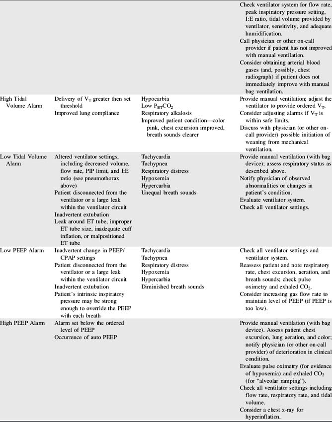
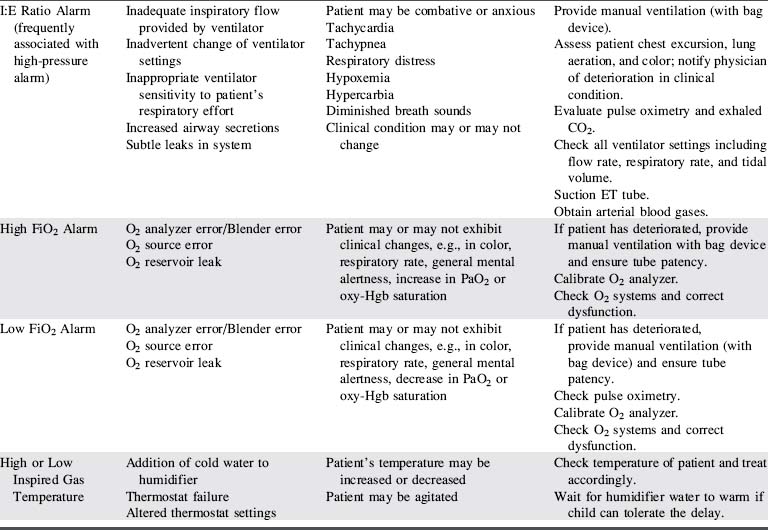
Frequently, ventilators with the widest possible clinical application are more practical to purchase than a large number of ventilators with very specific applications. The information in Box 21-2 and Table   21-11 should be considered when selecting ventilators for use with critically ill children, as well as selection of a specific mechanical ventilator for a particular patient.

Clinical Applications

Many of the newer-generation ventilators are capable of providing mechanical support across all or most patient populations. The incorporation of microprocessors into newer-generation ventilators has enabled this wide range of use.

Manufacturer's specifications and recommendations and hospital clinical trials should facilitate the selection of the ventilator(s) that can best serve each patient (e.g., the patient size limit for use of neonatal ventilators is generally 8-15   kg body weight). The clinical condition of the patient will determine the ventilator functions needed to provide optimal ventilation.

Nursing Considerations

Throughout mechanical ventilatory support, the bedside nurse is responsible for assessing effectiveness of ventilation. The use of mechanical ventilation does not ensure that the child is ventilated effectively. The ventilator settings must be evaluated constantly in light of the child's clinical appearance.

When ventilator function is in doubt, the child should be ventilated manually with a hand-resuscitator bag. Table   21-11 offers a troubleshooting guide for use when problems arise during mechanical ventilation. It is intended to address equipment (rather than patient) problems. For more information, see Chapter 9, Positive Pressure Mechanical Ventilation and the section, Nursing Care of the Child During Mechanical Ventilation).

High-Frequency Ventilation (HFV)

An alternative mode of ventilatory support is high-frequency ventilation (HFV). High-frequency ventilation uses a mean airway pressure (map) and rapid respiratory rates (60 to 3600/minutes) to recruit atelectatic regions of the lung. The tidal volumes used are close to anatomic dead space, so this form of ventilatory support does not create risk of volutrauma that can occur with administration of higher tidal volumes. Simply put, HFV allows for higher end-expiratory pressures with lower peak inspiratory pressures.

HFV is used for infants and children with acute lung injury when conventional ventilation has failed. A metaanalysis of HFV versus conventional ventilation in premature neonatesconcluded that the use of HFV did not reduce chronic lung disease or mortality in this patient group.27 With studies including only a small number of pediatric patients, a recent Cochrane analysis concluded that HFV did not improve outcome when compared with conventional mechanical ventilation.72a

There are two basic types of high-frequency ventilators—the oscillator and jet ventilator. Each is presented briefly here. For additional information, see Chapter 9.

High-Frequency Oscillatory Ventilation (HFOV)

High-frequency oscillatory ventilation (HFOV) employs a piston moving at extremely high frequencies (about 180 to 1500 cycles/minute) to create positive and negative pressure swings. Oscillatory ventilation does not produce bulk gas delivery. It uses a continuous gas flow to eliminate CO2 and deliver oxygen to the lung's ventilatory units.

In a controlled randomized multicenter NIH trial,75 HFOV offered no advantages over conventional ventilators in the treatment of neonatal respiratory failure. In this study the incidence of bronchopulmonary dysplasia was similar to conventional ventilation, and mortality rates were equal in both groups.

A randomized, crossover trial of HFOV versus conventional mechanical ventilation in 70 critically ill children with ARDS was published in 1994 by Arnold et al12a Children treated with HFOV demonstrated improved oxygenation and decreased use of supplementary oxygen 30   days later.

High-Frequency Jet Ventilation (HFJV)

The typical HFJV uses an oxygen source and a high-pressure source to deliver gas through a small-bore injector cannula that extends into the endotracheal (ET) tube. This system allows delivery of relatively large tidal volumes at relatively low peak airway pressures. A flow interrupter adjusts the frequency and relative inspiratory time. Valve devices applied to the expiratory limb of the circuit allow the application of PEEP. A continuous infusion of saline into the path of the jet humidifies inspired air. Often a conventional ventilator is used in tandem as the gas and oxygen source for the HFJV unit.

HFJV is used most often used as a rescue therapy for patients with respiratory failure unresponsive to conventional ventilation, as evidenced by rising inspiratory pressures, persistent hypoxemia, and hypercarbia despite maximal conventional ventilatory support. In recent years high frequency jet ventilation (HFJV) has become less widely used than HFOV.

Mechanisms of Gas Exchange with High Frequency Ventilation

The mechanisms of gas exchange during high-frequency ventilation are not well understood. As previously mentioned, bulk gas flow is not a major mechanism of gas exchange during HFV. Some gas exchange probably occurs simply because of nonhomogeneous alveolar filling and pressures.183 Other explanations include gas exchange resulting from turbulent mixing of gas molecules (“augmented dispersion”), gas convection, and diffusion.

Multiple mechanisms are probably involved in gas exchange during high-frequency ventilation.183 Ultimately, the effectiveness of these mechanisms must be determined by the evaluation of the patient's response to support.

Nursing Considerations During High Frequency Ventilation

High-frequency respiratory support is very different from conventional mechanical ventilation. The nurse must be familiar with the principles of operation, assessment of effectiveness of ventilation, and the potential complications of the technique.

The assessment of the infant or child on HFV differs from conventional ventilation in the following ways:

1. The clinical progress of the patient is the ultimate indicator of the effectiveness of ventilatory support. Progress is determined through evaluation of the patient's general appearance, color, and blood gases.

2. The chest will not rise during HFV, but may instead appear to be fluttering or vibrating, often referred to as “chest wiggle.”183

3. During auscultation of breath sounds, “inspiratory” air movement is difficult to identify; the quality of the breath sounds is peculiar to the patient on HFV. Breath sounds have been described as resembling a continuous loud jack hammer and are very high pitched. Low-pitched breath sounds may, in fact, indicate poor ventilation or pneumothorax.

4. Auscultation of the heart rate is nearly impossible; some physicians instruct the nurse to briefly place the HFV on standby to assess heart tones. Without the ability to easily auscultate heart tones or blood pressure, the nurse relies on evaluation of color, perfusion, pulses, pulse oximetry, and invasive monitoring for cardiovascular assessment.

5. Assessment of quantity and consistency of secretions obtained from suctioning is critical. Changes in the quantity or consistency of secretions frequently indicates the need for adjustment of the humidification system. A change in secretion quantity or consistency also may herald the development of necrotizing tracheobronchitis. Water particles should be visible traveling down the jet tube; these particles help prevent the development of mucous plugs.86

Complications of High-Frequency Ventilation

Many of the potential complications of HFV are identical to the complications of conventional mechanical ventilation, but the development of the complication may be more difficult to detect during HFV than during positive pressure ventilation.

1. Pneumothorax: The risk of pneumothorax in patients receiving HFV is the same as with conventional ventilation. Pneumothorax may be difficult to recognize during HFV because breath sounds are difficult to evaluate. Clinical signs of pneumothorax may be acute, including severe respiratory distress, cyanosis, hypoxemia, and hypotension. Transillumination and chest radiography are used to confirm the diagnosis.

2. Tenacious secretions: Secretions tend to become very thick, and mucous plugs may develop,86 producing airway obstruction. It may be difficult to achieve adequate humidification. Suctioning should be performed with instillation of saline.86

3. Gas trapping: Gas trapping often occurs with HFV and causes carbon dioxide retention and decreased compliance. Gas trapping is most likely to occur when high tidal volumes and short expiratory times are used.183 The optimal HFV settings to minimize air trapping have not been determined.

Endotracheal Tubes

Endotracheal (ET) intubation may be necessary to establish or maintain a patent airway or to facilitate mechanical ventilatory support. Elective intubation is always preferable to intubation under emergency conditions.

Endotracheal Tube Characteristics and Sizes

Shape of the Tube

Some ET tubes are curved sharply to enable rapid intubation to the point of curvature. These tubes should not be used for more than a few hours, because it is difficult to pass a suction catheter beyond the curvature of the tube. Tubes with sharp curvature are designed for orotracheal use, so they can be very difficult to place nasotracheally.

Position Markings

A radiopaque line should be present along the length of the ET tube to allow radiographic verification of the tube's position. In addition, markings should be present at 1-cm intervals on the tube. Such markings allow the nurse to verify appropriate depth of insertion regularly so that tube displacement is detected immediately.

The depth of the tube insertion at the patient lips or nares should be recorded in the patient record and nursing care plan. The nurse should check the depth of insertion whenever the tube is retaped, when vital signs are obtained or if the patient deteriorates suddenly.

Cuffed Versus Uncuffed Tubes

In the past, uncuffed ET tubes were generally used for infants and children less than 8   years of age, because the cricoid diameter of a child is quite narrow and was thought to provide a natural seal around the tube. However, evidence published in recent years has demonstrated that the use of cuffed tubes during in-hospital care of young children produces no higher incidence of complications than the use of uncuffed tubes.92

Cuffed tubes may reduce the incidence of aspiration, and cuffed tubes may be preferable to uncuffed tubes in some patients (i.e., those with poor lung compliance, high airway resistance, or a large glottic air leak), provided the endotracheal tube size, position and cuff inflation pressure is monitored.92 The cuff inflation pressure is maintained according to manufacturer specifications, typically at 20 to 25   cm H2O.92

Endotracheal Tube Size Selection

The diameter of the child's trachea is smallest at the level of the cricoid cartilage; therefore an ET tube may pass easily through the vocal cords yet be too large at the level of the cricoid cartilage. The ET tube size is appropriate if a small, audible air leak is present when inspiratory pressure of approximately 20- to 30-cm H2O is provided. This small leak indicates that the tube is probably small enough to avoid excessive pressure on the trachea below the level of the vocal cords.

If the tube is too large, an air leak is not detected even at positive pressure of more than 25 to 30   cm H2O. A tube that is too large can cause injury to the trachea.

If the tube is too small, an air leak is detectable at even low (<  10 to 15   cm H2O) inspiratory pressures. If the tube is too small and allows a substantial air leak, it may be impossible to provide adequate oxygenation or ventilation through the ET tube.92

The child's body length provides the best parameter for estimation of appropriate ET tube size.142 The relationship between body length and proper ET tube size has been used in the development of the Broselow resuscitation tape, which enables determination of appropriate endotracheal tube sizes, resuscitation equipment sizes, and drug dosages using the child's body length (see Figure 1-1).3,108

Several formulas enable estimation of ET tube size from age in children. The most popular formulas for estimation of uncuffed and cuffed tube sizes for children 1 to 10   years of age are:92

Uncuffed ETT (internal diameter [I.D.] in mm) = (age/4) + 4

Cuffed ETT (internal diameter [I.D.] in mm) = (age/4) + 3.5

These formulas provide a relatively accurate estimate of ET tube size (within 0.5   mm) in most children 1 to 10   years of age. Additional guidelines for estimation of proper ET tube size include the approximation of the size of the patient's little finger or the equivalent of the size of the child's nares.

Essential equipment for endotracheal intubation trays is listed in Table   21-12. Suggestions for intubation equipment size according to the child's age in years are listed in the table.

Table 21-12 Essential Equipment for Endotracheal Intubation

Essential Equipment for Intubation
Laryngoscope handle (2) Suction catheter to fit endotracheal tube
Curved and straight laryngoscope blades Tonsil suction (Yankauer tube)
Endotracheal tubes (three sizes) Foam donut head rest
Stylet Oropharyngeal airways
Bag and Mask Magill forceps or Kolodny hemostats
Oxygen source 1-inch tape
Suction set-up Benzoin
Guidelines for Pediatric Endotracheal Tube Sizes
Age/Size mm Internal Diameter*
Premature newborn  
1000   g 2.5
1000-1500   g 3.0
1500-2500   g 3.5
Full-term Newborns 3.5-4.0
6-12   months 4.0-4.5
1-2   years 4.5
4   years 5.0
6   years 5.5
8   years 6.0
10   years 6.5
Greater than 12   years  
Female 6.5-8.0
Male 7.5-8.0

Note: Intubation should be attempted by an experienced or closely-supervised clinician with resuscitation equipment immediately available.

* An ET tube size 0.5 mm larger and one 0.5   mm size smaller than predicted size should be immediately available to accommodate unexpected anatomical deviations.

From Czervinske MP, Barnhart SL: Perinatal and pediatric respiratory care, St Louis, 2003, Saunders.

Resuscitation Bags for Hand Ventilation

A variety of manual resuscitator bags are available, each with distinctive features. In general, there are two main types of bags: the self-inflating bag and the non–self-inflating (gas-inflating or so-called “anesthesia”) bag. The self-inflating bag does not require gas flow to provide manual ventilation; the non-self-inflating bag does require gas flow for use.

Self-inflating Bags

Self-inflating bags may be used with or without an oxygen source. The natural recoil of the bag causes the bag to re-inflate after it is compressed, whether or not the bag is connected to an oxygen (or other gas) source.

If the bag is connected to an oxygen source and a reservoir bag, 100% oxygen can be delivered to the patient, because even when the bag recoils, only oxygen is drawn into the bag and administered to the patient. If oxygen is joined to the bag without a reservoir, when the bag recoils room air can be drawn into (entrained into) the bag so it mixes with the oxygen; as a result the patient receives a mix of room air and oxygen.

The 0.5-L bag is generally appropriate for ventilation of infants through preschool-age children; the 1-L bags are used for children up to 8 to 10   years of age. The larger (i.e., 1.5 L) bags may be used for adolescents and adults.183

Clinical Use

Self-inflating resuscitation bags are particularly useful for resuscitation carts because they can be used without oxygen flow, if needed. If used during resuscitation, delivery of a high concentration of oxygen is typically needed, so the bag should include a reservoir and should be attached to oxygen flow as soon as possible. Self-inflating bags require less skill to use than non-self inflating bags.

These bags are also useful for patient transport, when it is frequently impossible to predict how much air/oxygen to carry. If the oxygen source is exhausted, the self-inflating bags still enable effective ventilation of the patient with room air until additional oxygen is obtained.

When the bag is used for ventilation through an ET tube, a pressure gauge should be used, joined to the bag (with a Y connector if necessary). This enables monitoring of peak inspiratory pressures delivered.

Most bags have a pop-off valve to prevent delivery of high pressures. These valves are not precise and it may be necessary to inactivate the pop-off valve to deliver adequate bag-mask ventilation during emergencies.

The bags typically contain a valve near the adaptor where the bag can be joined to the ET tube or a mask. Unless a low-resistance valve is present, the valve opens only when the bag is squeezed (to deliver breaths to the patient) and it closes while the bag recoils and refills with air. An adjustable PEEP valve can be added to maintain positive end-expiratory pressure.

Advantages

The advantages of self-inflating bags include ease of operation (operation of valves is not needed to deliver gas flow) and ability to operate without an oxygen or gas source.

Disadvantages

There are several disadvantages to the use of self-inflating bags. A reservoir must be added to the bag to enable provision of a FiO2 greater than 0.60.

If an inspiratory pop-off valve is present in older bags (set at 40   mm Hg to prevent the delivery of high inflation pressures), the pop-off valve may prevent delivery of adequate tidal volume during bag-mask ventilation, particularly if there is low airway or lung compliance.

The operator must be familiar with appropriate manual ventilation technique. Because these bags have thicker walls than nonself-inflating bags, it is more difficult for the operator to assess the compliance of the patient's lungs during bag-mask or bag-tube ventilation. A quick, snapping motion on inspiration should be avoided because this technique creates excessive inspiratory pressure that will open the pop-off valve (if one is present) and result in loss of tidal volume (i.e., air flow delivered to the patient).

Gas flow does not occur during spontaneous patient inspiration unless a low-resistance valve is present in the bag to allow the patient to draw in gas from the bag between manually delivered breaths. In many models a valve between the mask-adapter and the bag is opened only by the force of bag compression, so gas flow (and delivery of supplementary oxygen through the bag) during spontaneous ventilation is impossible.

The volume delivered during manual ventilation may be variable and depends on the speed and force of bag compression (and recoil) and patient lung compliance. The oxygen concentration delivered to the patient can also vary widely; if a reservoir is attached to the bag an FiO2 of 1.00 (100% oxygen) may be reliably delivered.

Non–Self-inflating Bags

Non–self-inflating resuscitation bags are collapsed at rest. They inflate (and reinflate after each breath delivered) only if a continuous gas source is available. The gas flow to the bag must equal at least three to five times the patient's minute ventilation requirements to adequately fill the bag between breaths.

Clinical Use

The non-self-inflating bag (“anesthesia bag”) is used in patients with advanced airways; it is not used for mask ventilation. This bag is very useful for assisting respiratory efforts of spontaneously breathing patients, but can also be used for those with no spontaneous respiratory effort.

The operator can deliver a relatively consistent tidal volume to patients who have decreased lung compliance. If the patient is breathing spontaneously, the patient can receive gas flow from the bag between delivered breaths.

Advantages

There are many advantages of this type of resuscitation bag. A FiO2 of 1.0 can be provided without the addition of a reservoir bag. The bag and adaptor itself contain no internal valves that might dysfunction. During ventilation the provider can easily assess the patient's lung compliance because the walls of the bag are not thick and there are no valves between the bag and the patient's endotracheal tube/airway.

As noted previously, patients can breathe spontaneously and receive a continuous flow of oxygen even when the bag is not squeezed. A CPAP/PEEP valve (that provides resistance to exit of gas from the bag) and a pressure gauge easily can be added to the system.

Disadvantages

The use of this bag requires much greater skill than the use of the self-inflating bag. The use of the bag is best learned in a controlled environment. The operator must be able to monitor the patient and the patient's chest rise while ensuring that gas flow into and out of the bag is adequate.

The provider must be able to adjust gas flow into the bag so the bag will quickly reinflate between delivered breaths yet avoid delivery of high inspiratory pressure to the patient. If gas flow to the bag is insufficient, it will be impossible to deliver an adequate tidal volume and respiratory rate.

The risk of pneumothorax is significant when this bag is used by an inexperienced operator. If the gas flow to the bag is too high in light of the patient's minute ventilation, or if the PEEP valve is adjusted incorrectly, the bag may quickly become distended and ventilation may be delivered at a high pressure. Finally the bag requires a continuous flow of gas, which may be a problem during field resuscitations, such as transports.

Neurologic monitoring devices

Jodi E. Mullen

Neurologic monitoring devices are used in the pediatric critical care unit to measure intracranial pressure (ICP) and enable drainage of cerebrospinal fluid (CSF), to monitor cerebral oxygenation, or for evaluating cerebral electroencephalographic (EEG) activity. Multimodal monitoring incorporates several neurologic monitoring parameters to evaluate the patient, and may yield additional information about the patient's overall clinical status.

As with the use of any monitoring or support device, it is imperative that the nurse be familiar with the monitoring technique or device itself, interpretation of values provided, and troubleshooting of the system. No one measurement will be as valuable as evaluation of trends in the measurements over time. As a result, the bedside nurse must ensure that measurements are performed consistently so that errors may be eliminated or standardized.

Invasive Intracranial Pressure (ICP) Monitoring

Invasive monitoring of intracranial pressure (ICP) is often a valuable adjunct to the care of the child with head injury, mass lesions, or metabolic encephalopathy. Measurement of ICP is also used in calculation of the cerebral perfusion pressure (CPP), and can provide indirect information about cerebral compliance and autoregulation. Intracranial pressure monitoring is especially useful when a patient is comatose or heavily sedated and clinical evaluation of neurologic function is difficult.

Common methods of ICP monitoring include intraventricular monitoring using a fluid-filled system, and advanced technologies that use fiberoptics or microchip sensors. An extraventricular drain (EVD) set can be coupled with an ICP monitoring system to enable cerebrospinal fluid (CSF) drainage as a therapeutic intervention. Intraventricular monitoring using a fluid-filled system has long been considered the definitive method of ICP monitoring.2

Fiberoptic and microchip devices can be implanted in the intraventricular and intraparenchymal compartments, and the epidural, subdural, and subarachnoid spaces. Although these systems allow flexibility of monitoring location with accuracy that is comparable to the fluid-filled system, a separate monitoring unit supplied by the manufacturer is needed, which adds to the cost as compared to ventriculostomy catheters.

A subarachnoid bolt or screw may also be used to enable monitoring of ICP. Table   21-13 provides a comparison of the advantages and disadvantages of some ICP monitoring systems.

Table 21-13 Comparison of Intracranial Pressure Monitoring Systems

Device Advantages Disadvantages
Intraventricular catheter with extraventricular drain (EVD)

Gold standard for ICP measurement

Can drain and sample CSF

Can set drip chamber at specific height (e.g., 15   cm) above ventricles so CSF will drain if ICP exceeds equivalent cm of water pressure (e.g., 15   cm H2O or 11.2 mm Hg)

Inexpensive in comparison to other systems

Invasive

Technically difficult to access ventricle in some patient situations

Catheter occlusion may develop

Transducer must be releveled when patient position changes

Risk of infection

System must be changed if drip chamber filter gets wet

Fiberoptic probe/microchip sensor

Flexibility in placement location

Accurate with movement of patient position

Calibrated before insertion

Minimal drift

Easily transported

Less risk of infection

Cannot be recalibrated after insertion

Fragile and prone to breakage

More expensive in comparison to other systems

Cannot drain or sample CSF unless an external ventricular drain set is also in use

Subarachnoid bolt/screw

Easily placed

Does not enter the brain

Possible lower infection risk

Catheter can become occluded by blood or tissue

Transducer must be releveled when patient position changes

May not be accurate with elevated ICP readings

May be difficult to place in young infants

Cannot drain or sample CSF

CSF, Cerebrospinal fluid; ICP, intracranial pressure.

Intraventricular Monitoring and Extraventricular Drain Systems

A ventriculostomy is the creation of a hole in a ventricle, to enable ICP monitoring or drainage of CSF. Typically, a catheter is inserted into a lateral ventricle and the catheter is joined to a fluid-filled system to monitor intracranial pressure. An external ventricular drain (EVD) system is used to drain CSF. The advantages of this ventricular monitoring and drainage system include the direct ICP measurements and the ability to drain CSF during management of increased intracranial pressure.7,104,114

Description

A ventriculostomy catheter is introduced into one of the lateral ventricles, usually on the patient's nondominant side. A twist drill is used to create a burr hole through which the catheter is advanced. Once the ventricle is reached the catheter may be tunneled through the scalp via a separate incision or sutured to the scalp at the insertion site. The catheter is then joined to an external fluid-filled monitoring system (with transducer) and to a stopcock and a closed, sterile drip chamber and receptacle for CSF collection.

External ventricular drainage systems include tubing between the catheter and the drip chamber, a stopcock, a drip chamber with a one-way valve, and a collection bag (Fig. 21-35). Many systems contain a built-in level indicator to facilitate leveling of the transducer with the patient's lateral ventricles (typically the external auditory canal is used as a landmark); the lateral ventricles are considered the zero reference point of the system.

image

Fig. 21-35 Intraventricular intracranial pressure (ICP) monitoring system with an external ventricular drainage system for controlled drainage of cerebrospinal fluid. A, The system consists of an intraventricular catheter joined by tubing to a drainage system with adjustable height and a drainage bag. The system also typically has a stopcock, an injection sampling port, and a clamp. The zero reference point for the system is typically between the outer canthus of the eye and the external auditory canal (see leveling device placed at that level). B, The drip chamber pressure level (horizontal arrow) is placed a prescribed height (in cm) above this zero reference point. The drainage stopcock can allow continuous drainage or be turned to allow only intermittent drainage when the child's ICP exceeds a prescribed threshold. If the system is functioning and the stopcock is turned to drainage, CSF will drain from the child's ventricle into the collection chamber and ultimately into the drainage bag once the patient's ICP is sufficiently high. If the drip chamber is placed 27.2   cm (rounded to 27   cm) above the child's ventricles, drainage should occur if the child's ICP equals 27.2   cm H2O or 20   mm Hg (1.36   cm H2O pressure = 1   mm Hg pressure; 27.2   cm H2O pressure = 20   mm Hg pressure).

(Redrawn and modified from Owen A: Clinical guideline: external ventricular drainage. Great Ormond Street Hospital for Sick Children, Institute of Children's Health and University College of London, Revised, September, 2009.)

The flow of CSF to the collection unit is regulated by the height of the drip chamber above the ventricles; this height (in centimeters) creates resistance to CSF drainage equivalent to centimeters of water pressure. For every 1.36   cm the drip chamber is elevated above the ventricle, 1   mm Hg intraventricular/intracranial pressure is required to produce drainage of CSF into the chamber.

Typically the system and stopcocks are arranged to allow automatic drainage once the ICP reaches a pressure specified by the physician (or on-call provider). For CSF drainage to occur, the pressure in the ventricles must exceed the pressure created by the column of water between the ventricle and the drip chamber (1.36   cm H2O pressure = 1   mm Hg) in the collection system. If the drip chamber is placed 27.2   cm above the ventricle, resistance to CSF drainage is equal to 27.2   cm H2O pressure, or 20   mm Hg pressure. When intracranial pressure exceeds 27.2   cm H2O (or 20   mm Hg), if the stopcock is set to allow drainage between the ventricle and the drip chamber, CSF will flow into the collection system.

If the system is set to allow continuous CSF drainage, the measured ICP will never exceed the pressure equivalent to the centimeters (of water) that the drip chamber is elevated above the ventricles. Some providers may request that some or all ICP measurements be obtained with the drainage briefly interrupted (i.e., the stopcock is temporarily open only between the transducer and the ventricle). Such measurements may be requested if there is any deterioration in the patient's clinical status. Once the isolated ICP measurement is obtained, the stopcock is again opened to the drip chamber as well as between the transducer and the catheter.

If intermittent drainage is preferred, the stopcock is typically closed between the ventricle and the drip chamber (i.e., “off” to drainage) for most periods, and the stopcock is only opened to allow drainage at times specified by the physician or on-call provider. If such intermittent drainage is provided, the ICP may continue to rise and CSF drainage won't occur unless the stopcock is turned to allow drainage from the ventricle into the drip chamber.

The external transducer is secured to a fixed reference point, as ordered by the physician or on-call provider. Usually the transducer is leveled at the lateral ventricle; the landmark used is typically the external auditory meatus.102 Some centers use the outer canthus of the eye and others use the midpoint of the imaginary line between outer canthus of the eye and the external auditory meatus. While any of these points is acceptable, it is essential that a single leveling point is established, and every practitioner must use the identical zero reference point. Use of the same zero reference point enables identification of changes over time.

Risks and Complications of Intraventricular Monitoring and Drainage

The need for a ventriculostomy is weighed against the potential complications or difficulties. Use of an intraventricular catheter creates the risk of infection.113 The system should always be closed and sterile technique must be used if it is necessary to enter the system. Opening the system to sample CSF or rezero and flush the system (not the ventricular catheter) can increase the risk of infection.112

Care of the insertion site varies with institution policy, but observation of the site, maintenance of the integrity of the dressing, and immediate reporting of redness or drainage are routine nursing responsibilities. If a catheter infection is suspected, the catheter is removed and appropriate antibiotic therapy initiated. If ICP monitoring is still required, another catheter may be placed in the opposite lateral ventricle. There are commercially available EVD catheters with antibiotic-coated tips that may reduce infection rates, but their routine use in clinical practice requires more research.24

When the catheter is passed through brain tissue, there is a risk of interrupting blood vessels. Although the reported incidence is low, resulting hemorrhage may be considered clinically insignificant, and may not be reported in the literature.113 In one pediatric study, hemorrhagic complications were detected more often with the use of external ventricular drainage systems as compared with fiberoptic monitoring.8 In an effort to prevent hemorrhage, coagulopathies should also be corrected before the placement of any device.113

Blood or brain tissue can obstruct the tip of the catheter any time during catheter use. Obstruction also may occur from compression of the ventricles by cerebral swelling. Additionally, the catheter can migrate or be misplaced or become displaced during use. The external tubing can also become kinked or can remain inadvertently clamped. If CSF drainage decreases or is lower than expected, obstruction or misplacement should be suspected. The pressure tracing may also become dampened or eliminated. The cause of obstruction and location of the catheter tip can be determined by means of a computed tomography (CT) scan.

The flow of CSF is caused by a pressure gradient between the ventricles and the drip chamber. The flow chamber should not be placed below the zero reference point, because that could cause excessive drainage with resulting collapse of the ventricles. Ventricular collapse can result in lateral or upward brain herniation or tearing of bridging veins as the brain tissue is pulled from the dura. Subdural or subarachnoid hemorrhage can result.

During periods of high volume CSF drainage, the child may develop hyponatremia because CSF sodium is unavailable for reabsorption and is lost in the external drain. It may be necessary to replace the CSF drainage with an equivalent volume of intravenous saline solution to maintain euvolemia and adequate serum sodium concentration.

If the system drip chamber is placed too high in relation to the zero reference point (e.g., as a result of patient movement or inadvertent movement of the drainage point), it will create too much resistance to drainage. As a result, CSF drainage will be inhibited until the ICP is high enough to overcome the resistance created by the fluid column between the ventricle and the drip chamber. This increase in ICP could be detrimental.

Maintenance and Nursing Considerations

The nurse must monitor the patient and the system closely to detect clinical changes, ensure accuracy of ICP measurements, and prevent complications. Whenever the patient deteriorates clinically, the nurse should assess the patient, check the monitoring and drainage system, and notify a physician or on-call provider immediately. If the ICP measurement or drainage changes acutely, the nurse should assess the patient first and then check the system.

Establishing the Monitoring and Drainage System

Once the ventriculostomy is in place, the transducer is leveled and secured at the zero reference point (the lateral ventricles). The drip chamber, with pressure level indicator, is positioned at the prescribed height in relation to the patient's lateral ventricles. The monitoring system is zeroed to atmospheric pressure, and then opened between the transducer and the ventricle. If ordered, the stopcock is turned so it is also open to drain.

If the system is to be used for continuous drainage, the stopcocks and clamps are placed in the open position, and CSF drainage will automatically occur when the ICP increases sufficiently to overcome the resistance provided by the height of the column of fluid in the collection system. For example, if the chamber is placed at 15   cm above the patient's ventricle, CSF drainage will occur whenever the ICP exceeds 11   mm Hg (15   cm ÷ 1.36   cm/mm Hg pressure = 11.02   mm Hg). As a rule, the chamber is positioned so that CSF drainage occurs as needed to keep the ICP at a reasonable level.

As noted previously, if the drainage system is functioning properly, the ICP should never exceed the pressure equivalent to the cm H2O pressure or resistance created by elevation of the drip chamber above the ventricle; venting of the CSF should prevent such rises. If the ICP does exceed the pressure within the collection system, obstruction of CSF drainage is probably present and the on-call provider should be notified immediately.

When the CSF is drained continuously, it is difficult to determine the severity of increases in intracranial volume and pressure that would occur in the absence of the drainage system. However, if CSF drainage is continuous or if it increases in amount, intracranial volume must be high or rising. To monitor the patient's intracranial pressure intermittently, drainage may be interrupted briefly with the stopcock turned off to drainage. The ICP and CPP are quickly measured and recorded, and then the stopcock is turned back to allow ongoing drainage. This procedure is generally performed at routine intervals as ordered (e.g., every 1 to 2 hours).

As noted in the preceding Description section, the ventriculostomy drainage (or extraventricular drain) system can also be used for intermittent CSF drainage. In this case, the practitioner specifies the location of the drip chamber, and specifies that the drainage stopcock is typically to be turned off to drainage but opened to allow drainage only if the patient's ICP reaches a specified value (usually 20 to 25   mm Hg). Whenever such drainage occurs, the patient's ICP will fall to the level equivalent to the pressure within the collection system, and the drainage stopcock should then be turned off to drainage. If frequent CSF drainage is required, the nurse should notify the physician or on-call provider.

Nursing Care and Maintenance of the System

As noted in the first paragraph of this Maintenance and Nursing Considerations section, the nurse should assess the patient and verify patient status before troubleshooting the equipment whenever the patient deteriorates, the measured ICP rises or if a problem develops the system. Report signs of patient deterioration immediately to the physician or on-call provider.

Carefully inspect the system at regular intervals to verify integrity of the system, confirming that clamps and stopcocks are appropriately opened or closed as ordered. Monitor the volume of CSF drainage and notify the physician or on-call provider if the CSF drainage volume varies from the expected.

Nursing documentation should include the characteristics and amount of drainage, the condition of the drainage system (open vs. clamped), and the appearance of the insertion site and dressing. The ICP and CPP are documented at frequent, regular intervals along with changes in ICP associated with patient care activities, such as suctioning. It is important to record the patient's tolerance of maintenance activities and any unexpected responses.

Inspect the dressing and tissue around the ventriculostomy at regular intervals. The dressing around the insertion site must remain clean and dry. Report signs of catheter site inflammation and any signs of potential infection (e.g., fever, leukocytosis) to a physician or on-call provider immediately. The risk of infection increases the longer a ventriculostomy remains in place.113

The CSF in the drip chamber should be emptied into the CSF drainage bag when the drip chamber is approximately two-thirds full. The fluid level in the chamber must be well below the level of the drip chamber where the filter is positioned. If fluid fills the chamber or the filter becomes wet, drainage can be obstructed and it will be necessary to replace the entire system.

The CSF drainage bag should be changed when it is approximately three-fourths full. Use personal protective equipment as appropriate for this procedure and dispose of the bag according to hospital biohazard procedures.

To move a patient or reposition the head:

1. Follow the practitioner's order for repositioning the patient or moving the patient out of bed.

2. Clamp the system and observe the patient's tolerance of the clamped drain during the process of moving.

3. Reposition or ambulate patient as ordered.

4. Re-level the transducer (and zero reference point for the system) at the level of the ventricle and the drip chamber at the appropriate height, at the level ordered by the practitioner.

5. Unclamp the system; observe and document the initial volume of fluid that drains.

If obstruction of the ventricular catheter is suspected, a physician (or other on-call provider) should be notified. The physician may gently attempt to instill a small amount of sterile saline into the catheter. As a rule, the catheter is not aspirated, because this can cause hemorrhage.

Fiberoptic and Microchip ICP Transducers

Description

Both the fiberoptic and the microchip ICP transducer can be used to monitor ICP. Either device may be placed in the lateral ventricles, the brain parenchyma, or the subdural, subarachnoid, or epidural space.

The fiberoptic monitoring device transmits light along a fiber (the optical fiber, or fiberoptic, contained in the catheter) to the tip of the catheter and transmits reflected light back to the base unit. A pressure transducer is located near the catheter tip. The mechanical diaphragm of the transducer moves with changes in pressure, and the movement will change the intensity of the light reflected off the diaphragm. The light refraction is then analyzed to derive a pressure reading that is displayed digitally on the ICP monitoring unit display (Fig. 21-36). The fiberoptic catheters must be zeroed before insertion; they are calibrated at the factory and cannot be recalibrated after insertion.

image

Fig. 21-36 Camino fiberoptic intracranial pressure-monitoring system. The fiberoptic catheter is joined to an amplifier-connector, and it transmits signals to the Camino module. The module displays digital ICP pressure measurement, but must be joined to a bedside monitor to display a waveform and provide audible high-pressure alarms. A, Camino monitoring system with intraparenchymal or intradural monitoring. Inset shows connection of catheter and monitor cable—at this connection, zeroing of the catheter is performed before insertion. B, Camino monitoring system for epidural monitoring. (Redrawn from illustrations of fiberoptic intracranial pressure-monitoring system by Integra Camino, San Diego, California.)

The microchip transducer has a pressure sensor at the tip. A change in pressure moves the position of this sensor and causes changes in electrical resistance; these changes are transformed and displayed as ICP measurements. The microchip transducers must be zeroed before insertion; they are calibrated at the factory and cannot be recalibrated after insertion.

Both fiberoptic and microchip ICP monitoring catheters can be coupled with a conventional bedside monitor for waveform display, paper recording, and generation of audible pressure alarms. The portable pressure monitoring unit must be calibrated at regular intervals with the bedside monitor digital display; note that this calibration is not the same as zeroing and calibration of the ICP transducer system (as discussed in the next paragraphs).

The advantages of the fiberoptic and microchip transducers over other systems are accuracy, versatility, small size, and minimal maintenance requirements. Because the transducers are located very near the tip of the catheter, leveling of the transducer to an anatomic reference point is unnecessary. As a result, valid pressure measurements are obtained even with frequent change in patient position.

This system is not dependent on transmission of pressure through a fluid-filled segment of tubing; artifact from air bubbles or particles does not occur. Zeroing is necessary only once before insertion and catheter calibration is performed at the factory. Catheters are also available to enable simultaneous ICP monitoring and CSF drainage (Fig. 21-37), as well as brain temperature monitoring.

image

Fig. 21-37 Camino intraventricular monitoring catheter with cerebrospinal fluid drainage system. The sheath of the intraventricular catheter provides a Y connection to a CSF drainage system. Drainage may be accomplished intermittently or continuously, with simultaneous pressure monitoring. The height of the drainage chamber above the ventricles will determine the ease of CSF drainage. (Redrawn from illustrations of intraventricular monitoring catheter with cerebrospinal fluid drainage system by Integra Camino, San Diego, California.)

Risks and Complications

The fiberoptic and microchip catheters require careful handling to avoid damage; the catheter must be replaced if it is damaged. Drifting of the zero reference point may be observed and can increase daily for as long as the catheter is in use.113 Manufacturer's recommendations should be followed regarding catheter replacement when monitoring is required for longer than 5   days.

Infection remains a potential problem with any ICP monitoring device. However, because there is no fluid incorporated in these devices, the incidence of infection may be lower than with fluid-filled monitoring systems. As with any invasive monitoring system, however, attention should be given to ensuring sterile technique during insertion, and aseptic technique during catheter and tubing care.

Complications associated with fiberoptic or microchip ICP monitoring are similar to those described previously for ICP monitoring and ventricular drainage. These include hemorrhage and obstruction, migration, and misplacement.

Maintenance and Nursing Considerations

These catheters are fragile. Care must be taken to avoid any tension on or compression of the catheter. All providers who care for patients with a fiberoptic or microchip ICP catheter must be extremely careful during handling of the patient and catheter. Damage to the light fibers of a fiberoptic catheter can occur readily. At regular intervals, the nurse should assess the security of the catheter at the insertion site.

The catheter must be inserted under sterile conditions and maintained with aseptic technique. The dressing around the insertion site must remain clean and dry. The risk of infection increases the longer a catheter remains in place.113

These catheters are zeroed before insertion; once the catheter is inserted, the zero is never adjusted. However, the calibration of the bedside monitor should be checked according to the manufacturer's recommendations, to ensure correlation between the ICP monitor and bedside monitor.

If the patient requires transfer to another location, ICP monitoring may be continued during transfer because the portable monitoring unit contains a rechargeable battery. If ICP monitoring is not performed during patient transfer and the catheter is disconnected, the ICP monitor will not lose calibration and the catheter transducer tip does not lose its zero reference point. However, once the ICP monitoring unit is reconnected to a bedside monitor, the bedside monitor must be recalibrated with the ICP monitor.

If a ventriculostomy drainage system is used, nursing documentation should include the characteristics and amount of drainage. The condition of the drainage system (open vs. clamped), and the appearance of the insertion site and dressing are also documented.

The ICP and CPP are documented at frequent, regular intervals along with changes in ICP associated with patient care activities, such as suctioning. The patient's tolerance of maintenance activities and any unexpected responses or deterioration are reported to a physician or other on-call provider.

ICP Monitoring with a Subarachnoid Bolt or Screw

Description

Another alternative method of ICP measurement is the use of a conventional fluid-filled transducer tubing system connected to the subarachnoid space with either a catheter or subarachnoid bolt or screw, respectively (Fig. 21-38). The transducer and tubing preparation is similar to that used for other fluid-filled monitoring systems; in these neurologic monitoring systems, however, a flush solution and continuous flow device are not used.

image

Fig. 21-38 Subarachnoid bolt. The bolt may be placed in the frontal area through a burr hole. To monitor pressure using a fluid-filled monitoring system, a short piece of (flushed) noncompliant tubing is used to join the bolt to a transducer. A fiberoptic catheter also can be placed for subarachnoid pressure monitoring.

A short, direct segment of tubing from the bolt (or catheter) is joined to a transducer. Care must be taken to prime the transducer system with preservative-free saline to eliminate all bubbles before joining the system to the bolt or catheter.

Advantages and Disadvantages

The advantages of using a subarachnoid bolt or screw include ease of insertion, minimal risk of brain tissue injury, and its improved accuracy in the presence of central edema, when the lateral ventricles may be compressed and difficult to catheterize.10,114

A disadvantage to the bolt is that it can become occluded with blood clots, tissue, or debris, which can dampen the ICP waveform and cause erroneous results.10,114 This system may not be accurate when the ICP is elevated (the very condition it is designed to monitor).182 As with other devices that enter the skull, infection, leak of CSF, and hemorrhage can occur.10,102 Subarachnoid bolts or screws are difficult to place in infants because of the pliability of the infant skull.

Maintenance and Nursing Considerations

Nursing care and maintenance of the system are similar to other ICP monitoring devices and include evaluating and documenting the integrity of the system, and taking precautions to prevent infection.

ICP Monitoring Equipment Preparation and Insertion

The steps for preparing a fluid-filled system or a fiberoptic or microchip transducer with its associated ICP monitor vary depending on the device, and the nurse should follow the manufacturer's guidelines. Box 21-3 lists the standard equipment and steps for inserting an ICP monitor.

Box 21-3 Intracranial Pressure Monitoring Equipment: Preparation and Insertion

1. Assemble the required equipment:

a. Sterile gloves, surgical gowns, towels, and drapes
b. Surgical caps and masks with protective eyewear
c. Hair clippers
d. Antiseptic scrub solution
e. Local anesthetic and syringe with needle
f. Cranial access kit, as supplied by the manufacturer
g. Hand drill with appropriate drill bit
h. Surgical blade
i. Suture
j. Supplies for sterile dressing

2. Fluid-filled system

a. Catheter
b. Pressure tubing and external strain gauge transducer with bedside monitor cable
c. Preservative-free saline solution
d. External ventricular drainage set, if required

3. Fiberoptic or microchip system

a. Catheter
b. ICP monitor supplied by manufacturer
c. Preamp connector cable, supplied with monitor
d. Cable to join ICP monitor to bedside monitor

4. Insertion site will be clipped, prepared, and draped with sterile towels and/or drapes.

5. Sterile technique is used to make an incision that is extended to the bone.

6. A drill hole is then made through the outer and inner tables of the skull. If the catheter is placed in the subarachnoid space or parenchyma, a bolt is placed in the skull to secure the catheter. Otherwise, the catheter is sutured in place and a sterile dressing is applied.

7. Fluid-filled system:

a. Prepare the drainage system transducer and tubing and EVD set, if using, and flush with preservative-free saline solution.
b. Assist with the insertion of the ventricular catheter, as needed.
c. Connect the transducer tubing to the ICP catheter.
d. Before joining the ventricular catheter to the external ventricular drainage system, check to ensure that the clamp from the drip chamber to the collection bag is closed.
e. Mount the system on an IV pole with the zero reference point at the level of the patient's ventricle.
f. Adjust the drainage collection chamber until it is positioned at the specified height above the patient's ventricles.
g. Observe for CSF flow into the drip chamber.
h. Zero the bedside monitor and position the system's stopcock to measure ICP.

8. Fiberoptic or microchip system:

a. The practitioner will remove the catheter from the sterile package.
b. The nurse will attach the transducer connection to the preamp connector and ensure that the preamp connector is joined to the pressure monitor.
c. The catheter must be zeroed according to the manufacturer's instructions before insertion.
d. Assist with the insertion of the catheter, as needed.
e. If a ventriculostomy drainage system is to be used it should be joined to the ventricular catheter at the Y connection or via stopcock.
f. The pressure monitor should be joined by a cable to the bedside monitor. The bedside monitor must also be calibrated with the pressure monitor as per the manufacturer's instructions.

EVD, External ventricular device; ICP, intracranial pressure.

The procedure should always be explained to the patient and family, as appropriate, and informed consent obtained. The child should be appropriately monitored and the nurse should ensure that adequate analgesic and sedative medications are administered.

Brain Oxygen Monitoring

Early detection of cerebral hypoxia and ischemia in the injured brain is important for preventing secondary brain injury and associated morbidity and mortality. Brain oxygen monitoring enables continuous assessment of brain oxygenation and evaluation of the effect of clinical interventions designed to improve brain oxygenation.80,138,141

Neurologic monitoring of brain oxygen includes measurement of regional cerebral oxygenation and measurement of more global cerebral oxygenation. These systems can be used separately or together.

Brain Tissue Oxygen Monitoring

Description

Brain tissue oxygen monitoring catheters continuously measure the partial pressure of oxygen in local brain tissue (PbtO2); the PbtO2, in turn, reflects the net balance of cerebral oxygen supply and cellular oxygen consumption.111 This advanced technology has led to a better understanding of the impact that low oxygen states have on the injured brain.105

The brain tissue oxygen monitoring system consists of a triple lumen probe that is inserted via a burr hole into the parenchyma of the brain. When detailed information on cerebral oxygenation in an injured area is desired, the device is placed on the affected side of the brain, in the penumbra area (ischemic but viable tissue surrounding an infarcted or injured area). The probe may also be placed in the nonaffected hemisphere for a reflection of more global cerebral oxygenation.

The tip of the flexible microcatheter contains a polarographic Clark-type electrode. Oxygen diffuses from the cerebral tissue through the polyethylene-coated catheter wall and into an inner electrolyte chamber where the partial pressure of oxygen is converted to a current between a cathode and an anode.82,118 The amount of current generated is proportional to the PbtO2 and is displayed in mm Hg.82

After insertion, the probe is connected by an electrical cable to the monitoring system supplied by the manufacturer. Depending on the monitor selected, the screen displays PbtO2, brain tissue temperature, and ICP.

Advantages, Disadvantages, and Contraindications

The advantage of using this system over conventional ICP monitoring is that it enables the practitioner to evaluate cerebral oxygen delivery and demand in the brain. This can allow the practitioner to identify levels of brain tissue oxygen that may be associated with secondary brain injury, identify and correct conditions associated with reduced cerebral tissue oxygenation, and plan treatment interventions more specifically aimed at improving the oxygenation of the brain.99,188

As with any intracranial monitoring system, there is a risk of infection, hematoma, and displacement of the probe. After insertion of the monitor probe, it can take up to 2   hours for the PbtO2 to equilibrate after the microtrauma of the insertion procedure.181 The practitioner must be aware of this delay in measurements when making clinical decisions based on these parameters. Technical care should be taken in handling these catheters because they can be inadvertently dislodged, misplaced, or broken.

Contraindications to using this system include uncorrected coagulopathy and an infection at the insertion site.181

Maintenance and Nursing Considerations

The insertion supplies for the brain oxygen monitor are similar to those needed for inserting a fiberoptic ICP monitor (see Box 21-3). Follow the manufacturer's directions for assisting with inserting the probe, and calibrating and setting up the monitoring system.

After setup is complete and the probe's external ends are attached to the brain tissue oxygen monitor, a cable can be used to connect the brain oxygen monitor with the patient's bedside monitor so that values are displayed and alarm parameters can be set.

After insertion, the nurse should evaluate the insertion site frequently and maintain the sterile dressing. The PbtO2, brain temperature, and ICP values should be assessed and documented routinely as part of the patient's overall assessment, and when there is a change in clinical status or a clinical intervention. When the child must be transported, the probes are gently disconnected from the bedside monitor at the patient end using gentle pulling; the probe device should not be twisted.181

Jugular Venous Oxygen Saturation Monitoring

Description

Most of the cerebral venous circulation drains into the external jugular veins, where oxygen saturation can be monitored by spectrophotometry. Because the oxygen saturation in the jugular vein reflects the oxygen remaining after cerebral perfusion and oxygen extraction has occurred, trends in jugular venous oxygen saturation (SjO2) reflect the balance of global cerebral oxygen delivery to consumption and can be used to evaluate the effectiveness of therapies.

The SjO2 is used in conjunction with other monitored parameters such as ICP and CPP to evaluate and manage patients with cerebral ischemia. Continuous measurements are obtained via a fiberoptic catheter that is placed retrograde into the internal jugular vein. The catheter is threaded over an introducer and advanced until it sits in the jugular venous bulb.89 Although either the right or left jugular vein can be used, the right internal jugular vein is usually cannulated because it drains a greater proportion of blood from the sagittal sinus.180

The monitoring system uses wavelengths of light (two or three wavelengths, depending on the manufacturer). The light is emitted from the tip of the catheter and then reflected light is detected by a photosensor and transmitted to the base unit. A microprocessor determines the reflection of the different wavelengths of light and because oxygenated hemoglobin (hemoglobin saturated with oxygen) reflects light differently than desaturated hemoglobin, the relative reflection of light allows estimation of the relative percent of hemoglobin in the jugular vein that is saturated with oxygen. The percentage of the oxygenated hemoglobin in the total hemoglobin is expressed as SjO2.26

Advantages, Disadvantages, and Contraindications

A fall in the SjO2 will identify cerebral ischemia more specifically than ICP monitoring or evaluation of the CPP. However, a decreased SjO2 represents more global ischemia rather than a particular area of local injury.

One disadvantage of this monitoring system for pediatric patients is catheter size. Because the catheter may impede venous drainage or cause obstruction of the internal jugular vein, continuous SjO2 monitoring is usually not attempted for children younger than 8   years of age or those who weigh less than 30   kg.180

Potential complications include hematoma formation, venous thrombosis, infection, and the potential for catheter-associated bloodstream infection. The catheter can also become clogged with debris, resulting in false readings.

Continuous SjO2 monitoring is contraindicated in the patient with an infection at the insertion site (in the neck), neck trauma, impaired venous drainage, or jugular venous occlusion or malformation. This monitoring may not be appropriate for the patient with coagulopathy, brain stem or cervical spine injury, or tracheostomy.164

Maintenance and Nursing Considerations

Insertion supplies include sterile garb for those involved in the insertion procedure, skin antiseptic and local anesthetic, pressure transducer tubing, the catheter, and the oximetric monitor. Prepare the oximetric monitor according to the manufacturer's instructions.

After the catheter is placed, it is flushed, attached to a continuous flush solution, and attached to the monitoring system. Only flush solution should infuse into the catheter. An occlusive, sterile dressing is applied over the insertion site.

Follow the manufacturer's instructions for obtaining a jugular venous blood gas for calibration of and correlation with the oximetric monitor.89 The nurse should aspirate the blood calibration specimens from the catheter at a rate of 1 to 2   mL/minute (i.e., very slowly).114,164 This technique ensures accuracy of the measurements by avoiding contamination of the sample from extracranial blood that also drains into the jugular vein; such contamination could result in falsely high oxygen saturation in the blood calibration specimen.

The nurse should record or store the SjO2 readings hourly and the insertion site, catheter integrity, and stability should be assessed hourly. Inaccurate measurements can result when the child's head or neck is rotated because the catheter can become improperly positioned within the jugular vein. Slightly repositioning the patient's head or the catheter may help the nurse determine if a desaturation reading is accurate or is a result of catheter misplacement.

Follow the manufacturer's recommendations for calibration of the device and recalibrate the device whenever there is concern about the accuracy of the readings. Accuracy can be affected by the hemoglobin concentration, systemic arterial oxygen saturation, core body temperature, and serum CO2 levels.164

Complications of continuous SjO2 monitoring include potential infection, pneumothorax, nerve injury, thrombosis, and carotid artery puncture.114,178 To reduce the risk of infection, strict sterile technique must be used during insertion and aseptic technique used when manipulating the catheter.

Transcranial Cerebral Oximetry Monitoring

Description

Transcranial cerebral oximetry, also known as near-infrared spectroscopy (NIRS), is a technique used for observing changes in regional cerebral oxygenation (rSO2). Sensors contained in adhesive electrodes are placed (noninvasively) on the patient's forehead and light waves of near-infrared wavelength penetrate the scalp, skull, and brain tissue to a depth of a few centimeters. The light waves are then absorbed differentially by oxygenated and deoxygenated hemoglobin, so analysis of light absorption can enable estimate of the cerebral tissue oxygen saturation.

The system measures light waves that are absorbed or scattered back to two electrode detectors. The device is able to identify the difference between light reflected from shallow tissue (i.e., the skull) and that reflected from tissue under the skull to identify the deeper tissue light reflection. The percent of the total hemoglobin that is oxygenated is calculated and displayed on the monitor as a numerical value.26,169

Advantages, Disadvantages, and Contraindications

The NIRS monitoring system provides real-time continuous monitoring of tissue oxygenation. This oxygenation can be used to evaluate the effect of interventions on tissue oxygenation. The technology is not dependent on the patient's pulse, blood pressure, or temperature, so it can be used in a variety of clinical situations.

A disadvantage to this technology is that brain swelling can affect the accuracy and reliability of NIRS.25 Additionally, the light waves only penetrate a few centimeters and cannot be used to determine rSO2 measurements beyond that depth.

The accuracy of the measurements is affected by cerebral infarction, extraaxial hematomas, and extracranial blood.26 This monitoring technology may not be used when bandages cover the forehead where the sensors must be placed.

Maintenance and Nursing Considerations

A separate transcranial cerebral oxygen monitor must be supplied by the manufacturer. It displays both the rSO2 value and a graphic trend of the value over time. Small pediatric sensors are available and should be used for children less than 40   kg body weight. Because the skull of a child is much thinner than the skull of an adult, the algorithm for detecting the pediatric rSO2 is different than the algorithm used in adults.26,169

The nurse should follow the manufacturer's instructions for applying the disposable sensors to the frontal temporal area of the forehead (to the left and right of midline) and attaching them to the NIRS monitor. The sensors are not placed on the scalp.

The nurse should note the baseline rSO2 value. Rather than comparing a given result with an absolute range of normal values, the continuous rSO2 readings are most useful for evaluating trends and changes from the patient's baseline.26 The rSO2 is not a stand-alone value, and the nurse should incorporate the reading with other data collected from the patient's neurologic assessment and other monitoring devices.169

Transcranial Doppler Ultrasonography (TCD)

Description

The measurement of cerebral blood flow is important whenever the patient at risk for cerebral ischemia and infarction, particularly risk of cerebral vasospasm and vessel occlusion. Transcranial Doppler ultrasonography (TCD) is a noninvasive method for evaluating cerebral blood flow velocity through the cranium.

A 2-MHz ultrasound probe is held to a thin area of the skull, usually above the zygomatic arch, and velocity signals are displayed as pulsatile waveforms that can be recorded.180 The measurement is performed by a trained technologist and then interpreted by a radiologist.

Advantages and Disadvantages

TCD is portable and does not require patient transport. The measurement technique is usually performed intermittently, because extended monitoring is hampered by difficulty in maintaining the ultrasound probe in position over a long period of time.91 Patient movement can affect the accuracy of the study results.

Maintenance and Nursing Considerations

The nurse should anticipate that the measurement of cerebral blood flow via TCD will be performed intermittently, usually daily. It will be combined with other technologic monitoring for determining the patient's overall cerebral oxygenation and neurologic status.184

EEG Monitoring

Continuous EEG Monitoring

Description

The electroencephalogram (EEG) is used most frequently to monitor critically ill patients with intracranial hypertension or refractory status epilepticus, or those at risk for secondary ischemia after brain injury. Electrodes are placed on the scalp and head to detect neuronal electrical impulses; these impulses are recorded and the graphic recording is the EEG. The EEG waveform reflects the physiologic state of the cerebral tissue and is an indication of the cerebral metabolic state.114

Advantages and Disadvantages

Continuous cerebral EEG monitoring (cEEG) is useful for unconscious patients, those in status epilepticus, and those in a coma, including barbiturate-induced coma; it is also useful for evaluation of the patient receiving neuromuscular blockade. Many critically ill patients may require neuromuscular blockade for several reasons, such as ventilator management; therefore the cEEG can offer more sensitive detection of localized seizure activity in these patients and allows prompt treatment of status epilepticus.96 Continuous EEG can be combined with other multimodality brain monitoring, allowing the clinician to identify when the brain is at risk for injury and intervene before there is permanent damage.57

The EEG electrodes must be placed by a trained technologist, who must be available to reapply any electrodes that loosen during patient transport, movement, or care. Electrical interference from equipment in the critical care environment and patient movement can interfere with the EEG recording.

Maintenance and Nursing Considerations

The nurse will prepare the patient and assist with the placement of EEG electrodes, as needed. Electrodes should not be placed over areas of skin breakdown. Before electrode placement, the skin should be prepared with soap and water or alcohol. Because a loose or misplaced electrode will impact the EEG waveform, the nurse should be vigilant in assessing electrode placement and wires while performing patient care.

Bispectral Index

Description

The bispectral index (BIS) is a processed EEG parameter that is used to monitor the patient's response to sedatives and anesthetic agents.135 Data are obtained from a single electrode strip that is placed across the patient's forehead. Brain activity in this localized area is reflected in the BIS value, a derived parameter reported on a 0 to 100 linear scale.11 A value of zero indicates no brain activity, whereas an awake and interactive patient will have a BIS value near 100.

Advantages and Disadvantages

When it is difficult to assess the child's neurologic status or level of sedation, the BIS, in conjunction with other neurologic monitoring technologies, can provide useful information. This technology is beneficial for the patient who is placed in a drug-induced (e.g., pentobarbital) coma for ICP management.

BIS data can be tracked over time and can provide real-time feedback about the patient's response to interventions. Muscle activity from the patient's face and forehead can cause signal artifact and interfere with the BIS data reliability. The BIS should not be considered a stand-alone monitoring technology, but should be used in combination with other monitoring strategies to augment the clinical assessment.

Maintenance and Nursing Considerations

A separate BIS monitor must be supplied by the manufacturer. It displays both the BIS value and a graphic trend of the value over time. Follow the manufacturer's instructions for applying the disposable sensor to the patient's forehead. The nurse should monitor clinical signs of neurologic function (e.g., the Glasgow Coma Scale Score, Table 11-6 or inside back cover) and record the BIS value on a regular basis and in response to therapeutic interventions, including titration of sedatives and administration of neuromuscular blocking agents.

Thermoregulation devices

Monitoring of environmental and patient temperature in the pediatric critical care unit is extremely important. Small children have a large body surface area in proportion to their body mass and may lose heat very rapidly by conduction, convection, and radiation. Cold stress can cause increased oxygen consumption, which may compromise the cardiorespiratory function of the critically ill child.

Temperature-Sensing Devices

The assessment of temperature is one of the oldest evaluative tools in medicine; the patient's temperature can provide information about the severity and nature of illness. Core body temperature has been the most accepted form of temperature measurement, and can be derived from a variety of anatomic locations including the rectum, esophagus, bladder, brain, or pulmonary artery. If measurement of temperature from a core body area is not feasible, alternative locations include oral, axillary, temporal artery, and tympanic membrane.

In selection of temperature measurement devices for the pediatric critical care setting, safety, speed of measurement, accuracy, and convenience are important considerations. Guidelines for temperature measurement in critically ill adult patients recommend using core measurements when possible, followed by oral or tympanic membrane measurement, and lastly axillary or temporal artery measurement only when other methods are not available.133

Although no guidelines exist for temperature monitoring in pediatric critical care patients, the site selected to monitor the pediatric patient's temperature should be determined by the need for precise measurement and by the patient's age and physiologic status. After one site is elected for monitoring, it should be used consistently for ongoing measurements so that trends can be identified over time.116

Measurement by Heat Absorption

Thermoresistive thermometers, or thermistor tips, contain heavy metals that respond to changes in electrical resistance with small changes in temperature. A microchip inside the thermometer measures this resistance, and then converts it into a measurement of temperature. The temperature reading is displayed digitally in degrees Celsius or Fahrenheit. Standard electronic digital thermometers use this technology.

Thermoresistive thermometers have a rapid response time, which may be an important consideration in pediatrics and critical care. Although most thermistors record the standard range of temperatures, some are available for recording lower temperatures. Such thermometers should be acquired by a critical care unit for use with hypothermic patients.

Measurement by Sensing Heat Radiation: Tympanic Membrane Thermometers

The tympanic membrane temperature probe consists of an otoscope-like probe covered with a disposable plastic speculum. The probe and cover are attached to a probe handle that houses the infrared sensing electronics. This thermometer uses infrared radiation and a thermopile detector at the tip of the instrument to measure the tympanic temperature inside the ear.

There is debate about the reliability of tympanic thermometry to detect fever in pediatric patients. Although less accurate than direct measurements of core temperature,125 the tympanic temperature measurement is thought to be semiequivalent to core temperature because the tympanic membrane receives its blood supply from the same vasculature that supplies the hypothalamus.40

Procedure

The speculum probe is positioned in the ear canal by pulling the ear lobe down and back for children less than 3   years of age, and up and back for older children.179 The probe should fit snugly but not be painful. To initiate measurement, a scan button is depressed.

The sensor receives emitted infrared energy that is fed through an analog to a digital converter. The resultant temperature is displayed within seconds and can be displayed in either Celsius or Fahrenheit degrees. After use the disposable speculum probe cover is removed.

Advantages and Disadvantages

This method of temperature assessment is convenient and rapid. Additionally, there is relatively low potential for cross-contamination because the probe covers are disposable. Young children may be extremely frightened of an instrument that enters any orifice, including the ear.

The presence of otitis media may result in inaccurate readings. Tympanic temperature measurements can also be affected by the user's positioning of the device during measurement and the size of the child's ear canal.40

Measurement by Sensing Heat Radiation: Temporal Artery Thermometers

Description

Using infrared technology, the temporal artery thermometer captures the heat energy from the skin overlying the temporal artery, just below the skin on the forehead. A hand-held infrared scanner is used and provides an estimate of core body temperature using two sensors and an algorithm that incorporates a factor compensating for measured ambient temperature.90

Procedure for Use

To obtain a temporal artery temperature reading, the scanner is placed on the skin at the center of the patient's forehead. Begin the measurement by pressing and holding the scan button. Sweep the sensor located at the head of the thermometer horizontally across the forehead to the hairline. While still holding down the scan button, remove the sensor briefly from the skin and place it behind the earlobe to touch the skin overlying the mastoid process. Release the scan button for the digital temperature measurement to display. The skin tap is used to control for evaporative cooling of the forehead that occurs if the patient is sweating. If the temperature at the mastoid is greater than the measurement over the temporal artery, the temperature at the mastoid is displayed.

Advantages and Disadvantages

Temporal artery temperature measurement is rapid and noninvasive. It can be performed quickly and may not disturb the child. The instrument is easy to clean and relatively inexpensive. However, the accuracy of this method of temperature measurement has been debated and the clinician should select the method most appropriate for each patient care situation.90,133

Maintenance of Neutral Thermal Environment: Warming Devices

An essential aspect of caring for any critically ill patient is ensuring normal body temperature, which minimizes metabolic stress. Body temperature is affected by both heat production and heat loss. Heat loss may occur through any one of four mechanisms: evaporation, convection, conduction, or radiation. When selecting warming devices, each of these sources of heat transfer must be considered in relation to the device.

Risks of All Warming Devices

The most serious complication of any warming device is overheating, which can cause hyperthermia and increased oxygen consumption. Overheating may produce skin burns, particularly in a patient with poor circulation. The caregiver's impression of the temperature output of the device (i.e., the sensation of heat on the caregiver's hand) should not be used to estimate the amount of heat reaching the patient.

Insensible water loss can be a significant problem and can be exaggerated with concomitant use of phototherapy lights. Additional fluid administration may be required to replace the additional insensible water loss. Also, daily weights and fluid and electrolyte balance should be monitored (see Chapter 12).

Warming/Cooling Blankets

Description

Warming blankets use either forced air or convection to warm the patient. Forced air efficiently transfers heat to the patient by circulating hot air through a “blanket” that covers the patient.

Circulating warm water mattresses raise the patient's temperature and reduce conductive heat losses. The mattress is placed under the patient and warmed water circulates through the mattress.

A water mattress can also be used as cooling device: cool water is circulated through the mattress and conductive cooling lowers the patient's body temperature. Various manufacturers supply the heating or cooling unit and disposable blankets or mattresses.

Advantages and Disadvantages

Devices vary by manufacturer and they heat or cool based on a preset target body temperature. Many include a patient temperature probe and a servo-controlled mechanism to maintain a selected patient temperature.

There is an increased risk of burns when using a circulating water mattress with the child who is cold and peripherally vasoconstricted. The vasoconstricted child has decreased surface capillaries to dissipate heat.

Cooling blankets are not always well tolerated by patients and the blankets can cause thermal injuries to the skin. External cooling can result in reflex shivering and vasoconstriction as the body attempts to generate heat and counteract the cooling process. Shivering increases the patient's temperature, causes discomfort, and increases metabolic demands.

Maintenance and Nursing Considerations

The manufacturer's instructions should be followed for the setup, application, and safety management of any patient heating or cooling device. The nurse should monitor the patient's temperature and response to therapy, and assess the effectiveness of rewarming or cooling interventions. If substantial heat output of a device is necessary to maintain the child's skin temperature, the child's cardiac output may be inadequate.

Closed Infant Warmers (Incubators)

Description

The closed infant warmer is a useful bed for infants who require maintenance of a controlled thermal environment. Air in the closed incubator is warmed and recirculated.

Temperature in the closed infant warmer can be set manually or by a servo control that regulates the thermal environment in the incubator in response to the infant's skin temperature. The servo control mechanism operates by presetting a desired skin temperature; the heating element within the incubator adjusts the environmental temperature automatically. The use of a servo control device should prevent wide fluctuations in environmental temperature and will conserve the infant's energy.

Advantages and Disadvantages

In addition to providing heat, the closed infant warmer minimizes convective heat loss. Ambient humidity of about 40% is maintained in the incubator without the use of additional water. This is an advantage because the water can be a site for bacterial growth.

Access to the infant for general care occurs through portholes, which limit access to the infant in a critical situation. Heat loss can occur when the incubator is opened and can result from radiant heat transfer if the walls of the incubator are subjected to a cool environmental temperature (e.g., near an air conditioning vent or in an area with drafts, near windows, or near outside walls).

Nursing Considerations

When operating the closed warmer in servo control, place the skin temperature probe on the infant's abdomen away from bony areas.119 The infant should not lie on top of the probe.

The portholes of the isolette should be used to gain access to the patient; the door of the incubator should not be opened for routine care. If the infant must be exposed for procedures, a portable radiant warmer should be placed over the infant. Because the incubator impedes access to the infant, critically ill patients with numerous invasive monitoring lines may benefit from being placed in an open bed with a radiant warmer.

Open Radiant Warming Beds

Description

When infants and other critically ill patients require close monitoring, quick access, and temperature control, the use of open radiant warmers with servo control provide the most effective method of temperature regulation. The radiant warmer consists of electrically heated elements placed over the patient's bed to emit radiant heat above the patient. The heating elements can be obtained as part of a system with an infant bed or as a separate unit that can be placed over a bed.

Skin probes can be used to enable servo control heat regulation. Manual mode can be used to control the heat output, but the patient's temperature must be monitored closely to avoid wide temperature swings.

Advantages and Disadvantages

Quick access to the patient is facilitated by the use of over bed warmers. Unobstructed visibility allows continuous observation of the patient and of all equipment surrounding and attached to the patient. The servo control device usually includes alarms for high and low temperature as well as for indication of continuous or prolonged heating.

Disadvantages to the open warmer include heat loss by convection if the room is drafty and increased insensible water loss that may be as high as twice the normal rate. Assessment of hydration must be performed with even greater vigilance than usual when an overbed warmer is used, and fluid intake adjusted as appropriate.

Maintenance and Nursing Considerations

Whenever radiant warmers are used, the nurse must monitor the patient's core and skin temperature. The servo mode is safer for continuous thermal support and the manual mode should only be used for short-term warming.49 The skin temperature probe should be placed on the infant's abdomen away from bony areas119 and the infant should not lie on top of the probe.49 A rectal temperature probe should not be used for warmer control because the skin can be burned before normal core temperature is reached.

Risks of All Warming Devices

The most serious complication of any warming device is overheating, which can cause hyperthermia and increased oxygen consumption. Overheating may produce skin burns, particularly in a patient with poor circulation. The caregiver's hand sense of temperature should not be used to estimate the amount of heat reaching the patient.

Insensible water loss can be a significant problem and can be exaggerated with concomitant use of some phototherapy lights. Extra fluid replacement may be required to compensate for increased insensible water loss. Also, daily weights and fluid and electrolyte concentrations should be monitored.

Conclusion

This chapter has attempted to provide principles for the selection and use of the most common biomedical instruments employed in the critical care unit. In the final analysis, monitoring and support systems are a routine and vital part of nursing care, but the application of these devices should surpass operational principles and focus on accuracy and contribution to patient care.

The critical care nurse is expected not only to master the principles of operation for the various bioinstrumentation devices, but more importantly, to manage the information derived from these systems. Accountability for machine performance and data analysis are important in patient care. If effective, the instrumentation should support patient care rather than detract from it.

Acknowledgments

We acknowledge the following for their support and review of the cardiovascular section: Jayme Frank, Thomas B. Brazelton, Lester T. Proctor, and American Family Children's Hospital, University of Wisconsin at Madison.

References

1 Absi M.A., Lutterman J., Wetzel G.T. Noninvasive cardiac output monitoring in the pediatric cardiac intensive care unit. Curr Opin Cardiol. 2010;25:77-79.

2 Adelson P.D., Bratton S.L., Carney N.A., et al. Guidelines for the acute medical management of severe traumatic brain injury in infants, children, and adolescents. Chapter 7. Intracranial pressure monitoring technology. Pediatr Crit Care Med. 2003;4:S28-S30.

3 Agarwal S., Swanson S., Murphy A., et al. Comparing the utility of a standard pediatric resuscitation cart with a pediatric resuscitation cart based on the Broselow tape: a randomized, controlled, crossover trial involving simulated resuscitation scenarios. Pediatrics. 2005;116(3):326-333.

4 Agati S., Ciccarello G., Fachile N., et al. DIDECMO: a new polymethylpentene oxygenator for pediatric extracorporeal membrane oxygenation. ASAIO J. 2006;52(5):509-512.

5 Alsoufi B., Al-Radi O.O., Nazer R.I., et al. Survival outcomes after rescue extracorporeal cardiopulmonary resuscitation in pediatric patients with refractory cardiac arrest. J Thorac Cardiovasc Surg. 2007;134(4):952-959.

6 American Association of Critical Care Nurses. Evaluation of the effects of heparinized and nonheparinized flush solutions on the patency of arterial pressure monitoring lines: the AACN thunder project. Am J Crit Care. 1993;2(1):3-15.

7 American Association of Neuroscience Nurses. Guide to the care of the patient with intracranial pressure monitoring. Chicago: AANN; 2005.

8 Anderson R.C.E., Kan P., Klimo P., et al. Complications of intracranial pressure monitoring in children with head trauma. J Neurosurg Pediatr. 2004;101:53-58.

9 Andropoulos D.B., Stayer S.A., Diaz L.K., et al. Neurological monitoring for congenital heart surgery. Anesth Analg. 2004;99(5):1365-1375.

10 Arbour R. Intracranial hypertension: monitoring and nursing assessment. Crit Care Nurse. 2004;24:19-32.

11 Arbour R. Electroencephalograph-derived monitoring. In: Littlejohns L.R., Bader M.K., editors. AACN-AANN protocols for practice: monitoring technologies in critically ill neuroscience patients. Sudbury, MA: Jones & Bartlett, 2009.

12 Armola R.R., Bourgault A.M., Halm M.A., et al. AACN levels of evidence: what's new? Crit Care Nurse. 2009;29(4):70-73.

12a Arnold J.H., Hanson J.H., Toro-Figuero L.O., Gutierrez J., Berens R.J., Anglin D.L. Prospective, randomized comparison of high-frequency oscillatory ventilation and conventional mechanical ventilation in pediatric respiratory failure. Crit Care Med. 1994;22(10):1530-1539.

13 Australia & New Zealand ECMO influenza investigators, Davies A.: Extracorporeal membrane oxygenation for 2009 influenza A (H1N1) acute respiratory distress syndrome, (chair), JAMA. 2009;302:(17)

14 Bahrami K.R., Van Meurs K.P. ECMO for neonatal respiratory failure. Semin Perinatol. 2005;29(1):15-23.

15 Bajaj L.: Measurement of arterial blood gases and arterial catheterization in children, UpToDate. Version 17.2 DBE8E6A10D-998, . 2009.

16 Baldwin J.T., Borovetz H.S., Duncan B.W., et al. The national heart, lung, and blood institute pediatric circulatory support program. Circulation. 2006;113:147-155.

17 Band J.D., Gaynes R.: Prevention of intravascular catheter related infections, UpToDate. Version 17.2 BFF9EF5E22-998,. 2009.

18 Bastardi H.J., Naftel D.C., Webber S.A., et al. Ventricular assist devices as a bridge to heart transplant in children. J Cardiovasc Nurs. 2008;23(1):25-29.

19 Baulig W., Dullenkopf A., Kobler A., et al. Accuracy of continuous central venous oxygen saturation monitoring in patients undergoing cardiac surgery. J Clin Monit Comput. 2008;22(3):183-188.

20 Benditt J.O. Esophageal and gastric pressure measurements. Respir Care. 2005;50(1):68-75.

21 Bendjelid K., Schutz N., Stotz M., et al. Transctaneous PCO2 monitoring in critically ill adults: clinical evaluation of a new sensor. Crit Care Med. 2005;33(10):2203-2206.

22 Bernet-Buettiker V., Ugarte M.J., Frey B., et al. Evaluation of a new combined transcutaneous measurement of PCO2/pulse oximetry saturation ear sensor in newborn patients. Pediatr. 2005;115(1):e64-e68.

23 Beydon N. Pulmonary function testing in young children. Paediatr Respir Rev. 2009;10(4):208-213.

24 Bhatia A., Gupta A.K. Neuromonitoring in the intensive care unit. I. Intracranial pressure and cerebral blood flow monitoring. Intensive Care Med. 2007;33:1263-1271.

25 Bhatia A., Gupta A.K. Neuromonitoring in the intensive care unit. II. Cerebral oxygenation monitoring and microdialysis. Intensive Care Med. 2007;33:1322-1328.

26 Blissitt P.A. Brain oxygen monitoring. In: Littlejohns L.R., Bader M.K., editors. AACN-AANN protocols for practice: monitoring technologies in critically ill neuroscience patients. Sudbury, MA: Jones & Bartlett, 2009.

27 Bollen C.W., Uiterwaal C.S., van Vught A.J. Cumulative metaanalysis of high-frequency versus conventional ventilation in premature neonate. Intensive Care Med. 2007;33(4):680-688.

28 Bower L.K., Barnhart S.L., Betit P., et al. AARC Guidelines: neonatal and pediatric O2 delivery. Respir Care. 2002;47(6):707-716.

29 Boxer R.A., et al. Noninvasive pulse oximetry in children with cyanotic congenital heart disease. Crit Care Med. 1987;15:1062.

30 Bruce E., Franck L., Howard R.F. The efficacy of morphine and entonox analgesia during chest drain removal in children. Pediatr Anesth. 2006;16(3):302-308.

31 Bruce E.A., Howard R.F., Franck L.S. Chest drain removal pain and its management: a literature review. J Clin Nurs. 2006;15(2):145-154.

32 Cannon M.L., Cornell J., Tripp-Hammel D.S., et al. Tidal volumes for ventilated infants should be determined with a pnuemotachometer placed at the endotracheal tube. Am J Respir Crit Care Med. 2000;162(6):2109-2112.

33 Carberry K.E., Gunter K.S., Germmato C.J., et al. Mechanical circulatory support for the pediatric patient. Crit Care Nurs Q. 2007;30(2):121-142.

34 Carter R., Banham S.W. Use of transcutaneous oxygen and carbon dioxide tensions for assessing indices of gas exchange during exercise testing. Respir Med. 2000;94:350-355.

35 Cates L.A. Pigtail catheters used in the treatment of pneumothoraces in the neonate. Adv Neonatal Care. 2009;9(1):7-16.

35a Chameides L., Samson R.A., Schexnayder S.M., Hazinski M.F., editors. Pediatric advanced life support provider manual. Dallas: American Heart Association, 2011.

36 Cicek S.H., Gumus S., Deniz O., et al: Effect of nail polish and henna on oxygen saturation determined by pulse oximetry in healthy young adult female. Emerg Med J 2010.

37 Clermont G., Theodore A.: Arterial catheterization, UpToDate. Version 17.2,. 2009.

38 Collison S.P., Dager S.K. The role of the Intra-aortic balloon pump in supporting children with acute cardiac failure. Postgrad Med J. 2007;83:308-311.

39 Consumer Product Safety Commission: Extension cords fact sheet: CPSC document #16. 2007. http://www.cpsc.gov/cpscpub/pubs/16.html Accessed September 11

40 Craig J.V., Lancaster G.A., Taylor S., et al. Infrared ear thermometry compared with rectal thermometry in children: a systemic review. Lancet. 2002;360:603-609.

41 Cua C.L., Thomas K., Zurakowski D., et al. A comparison of the vasotrac with invasive arterial blood pressure monitoring in children after pediatric cardiac surgery. Anesth Analg. 2005;100(5):1289-1294.

42 Deckardt R., Steward D. Noninvasive arterial hemoglobin oxygen saturation versus transcutaneous oxygen tension monitoring in the preterm infant. Crit Care Med. 1984;12(11):935.

43 de Oliveira C.F., de Oliveira D.S., Gottschald A.F., et al. ACCM/PALS haemodynamic support guidelines for paediatric septic shock: an outcomes comparison with and without monitoring central venous oxygen saturation. Intensive Care Med. 2008;34:1065-1075.

44 Dickerson H.A., Chang A.C.: Perioperative management of ventricular assist devices in children and adolescents. . Semin Thorac Cardiovasc Surg Pediatr Card Surg Annu. 2006:128-139.

45 Di Fiore J.M. Neonatal cardiopulmonary monitoring techniques. Semin Neonatol. 2004;9(3):195.

46 Donn S.M., Sinha S.K. Advanced neonatal ventilation. In: Kurjak A., Chervenak F.A., editors. Textbook of perinatal medicine. Andover, UK: Informa Healthcare, 2006.

47 Duncan B.W. Mechanical circulatory support for infants and children with cardiac disease. Ann Thorac Surg. 2002;73:1670-1677.

48 Eberhard P. The design, use, and results of transcutaneous carbon dioxide analysis: current and future direction. Anesth Analg. 2007;105:S48-S52.

49 ECRI Institute. Infant radiant warmers can burn: use with care. ECRI Institute, 2009, available at http://mdsr.ecri.org/summary/detail.aspx?doc_id=8263, 2009. Accessed 11/29/09

50 Edelson D.P., Abella B.S., Kramer-Johansen J., et al. Effects of compression depth and pre-shock pauses predict defibrillation failure during cardiac arrest. Resuscitation. 2006;71:137-145.

51 Epstein A.E., DiMarco J.P., Ellenbogen K.A., et al. ACC/AHA/HRS 2008 guidelines for device-based therapy of cardiac rhythm abnormalities: a report of the American College of Cardiology/American Heart Association Task Force on Practice Guidelines (writing committee to revise the ACC/AHA/NASPE 2002 guideline update for implantation of cardiac pacemakers and antiarrhythmia devices) developed in collaboration with the American Association for Thoracic Surgery and Society of Thoracic Surgeons. J Am J Cardiol. 2008;51(21):e1-e62.

52 Fakler U., Pauli C., Balling G., et al. Cardiac index monitoring by pulse contour analysis and thermodilution after pediatric cardiac surgery. J Thorac Cardiovasc Surg. 2007;133(1):224-228.

53 Felix D.E., Munro H.M., DeCampli W.M. Near infrared spectroscopy used to detect preoperative aortic obstruction. Pediatr Anesth. 2007;17(6):598-599.

54 Field J.M., Hazinski M.F., et al. Part 1: executive summary: 2010 American Heart Association Guidelines for Cardiopulmonary Resuscitation and Emergency Cardiovascular Care. Circulation. 2010;122(suppl 3):S640-S656.

55 Finer N.N. Newer trends in continuous monitoring of critically ill infants and children. Pediatr Clin North Am. 1980;27(3):553.

56 Fowler R.A., Rizoli S.B., Levin P.D., Smith T. Blood conservation for critically ill patients. Crit Care Clin. 2004;20(2):313-324.

57 Friedman D., Classen J., Hirsch L.J. Continuous electroencephalogram monitoring in the intensive care unit. Anesth Analg. 2009;109:506-523.

58 Fuchs A., Netz H. Ventricular assist devices in pediatrics. Images Paediatr Cardiol. 2002;9:24-54.

59 Fullerton D.A., St Cyr J.A. Mixed venous oxygen saturation in the diagnosis of cardiac tamponade. J Cardiac Surg. 2008;23(2):180-181.

60 Gancel P.-E., Roupie E., Guittet L., et al. Accuracy of a transcutaneous carbon dioxide pressure monitoring device in emergency room patients with acute respiratory failure. Intensive Care Med. 2011;37(2):348-351.

61 Gawlinski A.D.N.S., Rutledge D. Selecting a model for evidence-based practice changes: a practical approach. AACN Adv Crit Care. 2008;19(3):291-300.

62 Gettinger A., DeTraglia M., Glass D. In vivo comparison of two mixed venous saturation catheters. Anesthesiology. 1987;66:373.

63 Gold L.S., Rear T.D., Eisenberg M.S.: Automated external defibrillators, UpToDate November 24, 2010. http://www.uptodate.com/contents/automated-external-defibrillators Accessed at

64 Gordon M.B.S.N., Bartruff L.M.S.N., Gordon S.M.S.N., et al. How fast is too fast? A practice change in umbilical arterial catheter blood sampling using the Iowa model for evidence-based practice. Adv Neonatal Care. 2008;8(4):198-207.

65 Graham K.C., Cvach M. Monitor alarm fatigue: standardizing use of physiological monitors and decreasing nuisance alarms. Am J Crit Care. 19(1), 2010.

66 Gravlee G., Davis R., Stammers A., Ungerleider R. Cardiopulmonary bypass: principles and practice, ed 3. Philadelphia: Lippincott Williams & Wilkins; 2007.

67 Griffin M.P., Siadaty M.S. Papaverine prolongs patency of peripheral arterial catheters in neonates. J Pediatr. 2005;146(1):62-65.

68 Hadaway L. Technology of flushing vascular access devices. J Infus Nurs. 2006;29(3):129-145.

69 Haddad F., Zeeni C., Yazigi A., Madi-Jebara S. Multimodal analgesia for chest tube removal after cardiac surgery. J Cardiothorac Vasc Anesth. 2006;20(5):760-761.

70 Hall K.F., Bennetts T.M., Whitta R.K., et al. Effect of heparin in arterial line flushing solutions on platelet count: a randomised double-blind study. Crit Care Resusc: J Aust Acad Crit Care Med. 2006;8(4):294-296.

71 Hawkin J.A., Minich L.L. Intraaortic balloon counterpulsation for children with cardiac disease. In: Duncan B.W., editor. Mechanical support for cardiac and respiratory failure in pediatric patients. New York: Marcel Dekker, 2001.

72 Hay W.W.Jr., Rodden D.J., Collins S.M., et al. Reliability of conventional and new pulse oximetry in neonatal patients. J Perinatol. 2002;22(5):360.

72a Henderson-Smart D.J., et al: Elective high frequency oscillatory ventilation versus conventional ventilation for acute pulmonary dysfunction in preterm infants. Cochrane Database Syst Rev. 2007:(3):CD000104

73 Hetzer R., Stiller B. Ventricular assist device for children. Nat Clin Pract Cardiovasc Med. 2006;3(7):377-386.

74 Heulitt M.J., Farrington E.A., O'Shea T.M., et al. Double-blind, randomized, controlled trial of papaverine-containing infusions to prevent failure of arterial catheters in pediatric patients. Crit Care Med. 1993;21(6):825-829.

75 Hi Fi Study Group. High frequency oscillatory ventilation compared with conventional mechanical ventilation in the treatment of respiratory failure. NEJM. 1989;320(2):88.

76 Hillier S.C., Schamberger M.S. Transcutaneous and end-tidal carbon dioxide analysis: complimentary monitoring strategies. J Intensive Care Med. 2005;20:307-309.

77 Hinkelbein J., Genzwuerker H.V., Sogi R., et al. Effect of nail polish on oxygen saturation determined by pulse oximetry in critically ill patients. Resuscitation. 2007;72(1):82-91.

78 Hirsch J.C., Charpie J.R., Ohye R.G., Gurney J.G. Near-infrared spectroscopy: what we know and what we need to know: a systematic review of the congenital heart disease literature. J Thorac Cardiovasc Surg. 2009;137(1):154-159.e12.

79 Hoffman G.M., Stuth E.A., Jaquiss R.D., et al. Changes in cerebral and somatic oxygenation during stage 1 palliation of hypoplastic left heart syndrome using continuous regional cerebral perfusion. J Thorac Cardiovasc Surg. 2004;127(1):223-233.

80 Horvath R., Shore S., Schultz S.E., et al. Cerebral and somatic oxygen saturation decrease after delayed sternal closure in children after cardiac surgery. J Thorac Cardiovasc Surg. 2010;139(4):894-900.

81 Huber D., Osthaus W.A., Optenhofel J., et al. Continuous monitoring of central venous oxygen saturation in neonates and small infants: in vitro evaluation of two different oximetry catheters. Pediatr Anesth. 2006;17:1257-1261.

82 Integra Neurosciences. Licox IMC directions for use. Plainsboro, NJ: Integra Neurosciences; 2004.

83 Kalavrouziotis G., Karunaratne A., Raja S. Intraaortic balloon pumping in children undergoing cardiac surgery: an update on the Liverpool experience. J Thorac Cardiovasc Surg. 2006;131:1382-1389.

84 Kannan A. Heparinised saline or normal saline? J Periop Pract. 2008;18(10):440-441.

85 Karl T.R., Horton S.B. Centrifugal pump ventricular assist device in pediatric cardiac surgery. In: Duncan B.W., editor. Mechanical support for cardiac and respiratory failure in pediatric patients. New York: Marcel Dekker, 2001.

86 Karp T., et al. High frequency jet ventilation: a neonatal nursing perspective. Neonatal Network. 1986;4(10):42.

87 Karselis T.C. Descriptive medical electronics and instrumentation. Thorofare, NJ: Slack; 1973.

88 Keszler M. State of the art in conventional mechanical ventilation. J Perinatol. 2009;29(4):262.

89 Kidd K.C., Criddle L. Using jugular venous catheters in patients with traumatic brain injury. Crit Care Nurs. 2001;21:16-22.

90 Kirk D., Rainey T., Vail A., et al. Infra-red thermometry: the reliability of tympanic and temporal artery readings for predicting brain temperature after severe traumatic brain injury. Crit Care. 2009;13:R81.

91 Kirkness C. Cerebral blood flow monitoring. In: Littlejohns L.R., Bader M.K., editors. AACN-AANN protocols for practice: monitoring technologies in critically ill neuroscience patients. Sudbury, MA: Jones & Bartlett, 2009.

92 Kleinman M., Chameides L., Schexnayder S.M., et al. Part 14: pediatric advanced life support; 2010 American Heart Association Guidelines for Cardiopulmonary Resuscitation and Emergency Cardiovascular Care. Circulation. 2010;122:S876-S908.

93 Kotake Y., Yamada T., Nagata H., et al. Can mixed venous hemoglobin oxygen saturation be estimated using a NICO monitor? Anesth Analg. 2009;109(1):119-123.

94 Krivitski N.M., Kislukhin V.V., Thuramalla N.V. Theory and in-vitro validation of a new extracorporeal AV loop approach for hemodynamic assessment in pediatric and neonatal ICU patients. Pediatr Crit Care Med. 2008;9(4):423-428.

95 Kuch B.A., Saville A., Vehovic W., et al: Accuracy of the sidestream vs. mainstream end tidal capnography: a Bland-Altman analysis. . 54th International Respiratory Congress, Anaheim, CA. 2008

96 Kurtz P., Hanafy K.A., Claassen J. Continuous EEG monitoring: is it ready for prime time? Curr Opin Crit Care. 2009;15:99-109.

97 Kussman B.D.B.C., Wypij D., DiNardo J.A., et al. Cerebral oximetry during infant cardiac surgery: evaluation and relationship to early postoperative outcome. Anesth Analg. 2009;108(4):1122-1131.

98 Lacerenza S., De Carolis M.P., Fusco F.P., et al. An evaluation of a new combined SpO2/PtcCO2 sensor in very low birth weight infants. Anesth Analg. 2008;107:125-129.

99 Lang E.W., Mulvey J.M., Mudaliar Y., et al. Direct cerebral oxygenation monitoring: a systematic review of recent publications. Neurosurg Rev. 2007;30:99-107.

100 Lawson D., et al. Blood flow limits and pulse oximeter signal detection. Anesthesiology. 1987;67(4):599.

101 LeSouef P.N., et al. Comparison of transcutaneous oxygen tension with arterial oxygen tension in newborn infants with severe respiratory illnesses. Pediatrics. 1978;62(4):692.

102 Leeper B., Lovasik D. Cerebrospinal drainage systems: external ventricular and lumbar drains. In: Littlejohns L.R., Bader M.K., editors. AACN-AANN protocols for practice: monitoring technologies in critically ill neuroscience patients. Sudbury, MA: Jones & Bartlett, 2009.

103 Link M.S., Atlins D.L., Passman R.S., et al. Part 6: electrical therapies, automated external defibrillators, defibrillation, cardioversion, and pacing, 2010 American Heart Association Guidelines for Cardiopulmonary Resuscitation and Emergency Cardiovascular Care. Circulation. 2010;122:S706-S719.

104 Littlejohns L.R., Bader M. Guidelines for the management of severe head injury: clinical application and changes in practice. Crit Care Nurse. 2001;21:48-65.

105 Littlejohns L.R., Bader M.K., March K. Brain tissue oxygen monitoring in severe brain injury. I. Crit Care Nurse. 2003;23:17-25.

106 Lopez E., Grabar S., Barbier A., et al. Detection of carbon dioxide thresholds using low-flow sidestream capnography in ventilated preterm infants. Intensive Care Med. 2009;35:1942.

107 Lopez-Briz E., Ruiz-Garcia V. Heparina frente a cloruro sodico 0,9% para mantener permeables los cateteres venosos centrales. Una revision sistematica. Farm Hosp. 2005;29(4):258-264.

108 Lubitz D.S., et al. A rapid method for estimating weight and resuscitation drug dosages from length in the pediatric age group. Ann Emerg Med. 1988;17:576.

109 Lund C.H., Osborne J.W., Kuller J., et al. Neonatal skin care: clinical outcomes of the AWHONN/NANN evidence-based clinical practice guideline. JOGNN. 2001;30(1):41-51.

110 Maar S.P. Searching for the holy grail: a review of markers of tissue perfusion in pediatric critical care. Pediatr Emerg Care. 2008;24(12):883-887.

110a Mahajan A., et al. An experimental and clinical evaluation of a novel central venous catheter with integrated oximetry for pediatric patients undergoing cardiac surgery: Pediatric Central Venous Oximetry. Anest Anal. 2007;105(6):1598-1604.

111 Maloney-Wilensky E., Gracias V., Itkin A., et al. Brain tissue oxygen and outcome after severe traumatic brain injury: a systematic review. Crit Care Med. 2009;37:2057-2063.

112 March K. Intracranial pressure monitoring and assessing intracranial compliance in brain injury. Crit Care Nurs Clin North Am. 2000;12:429-436.

113 March K., Madden L. Intracranial pressure management. In: Littlejohns L.R., Bader M.K., editors. AACN-AANN protocols for practice: monitoring technologies in critically ill neuroscience patients. Sudbury, MA: Jones & Bartlett, 2009.

114 March K., Wellwood J., Arbour R. Technology. In Bader M.K., Littlejohns L.R., editors: AANN core curriculum for neuroscience nursing, ed 4, Philadelphia: Saunders, 2004.

115 Martin J., Shekerdemian L.S. The monitoring of venous saturations of oxygen in children with congenitally malformed hearts. Cardiol Young. 2009;19(1):34-39.

116 Martin S.A., Klein A.M. Can there be a standard for temperature measurement in the pediatric intensive care unit? AACN Clin Issues. 2004;15:254-266.

117 Mattoo T. Definition and diagnosis of hypertension in children and adolescents. Pediatrics. 2009;104(3):30.

118 Mazzeo A.T., Bullock R. Monitoring brain tissue oxymetry: will it change management of critically ill neurologic patients? J Neurol Sci. 2007;261:1-9.

119 McGrath J.M. Neonatal thermoregulation. In: Verger J.T., Lebet R.M., editors. AACN procedure manual for pediatric acute and critical care. St Louis: Saunders Elsevier, 2008.

120 McSwain S.D., Hamel D.S., Smith P.B., et al. End-tidal and arterial carbon dioxide measurements correlate across all levels of physiologic dead space. Respir Care. 2010;55(3):288-293.

121 Miller-Hoover S., Small L. Research evidence review and appraisal: pediatric central venous catheter care bundling. Pediatr Nurs. 2009;35(3):191-201.

122 Mohseni-Bod H., Frndova H., Gaitaro R., et al. Evaluation of a new pediatric continuous oximetry catheter. Pediatr Crit Care. 2011;12(5):1.

123 Mok E., Kwong T.K., Chan M.F. A randomized controlled trial for maintaining peripheral intravenous lock in children. Int J Nurs Pract. 2007;13(1):33-45.

124 Monggero L., Beck J., editors. On bypass: advanced perfusion techniques. Totowa, NJ: Humana Press, 2008.

125 Moran J.L., Peter J.V., Solomon P.J., et al. Tympanic temperature measurements: are they reliable in the critically ill? A clinical study of measures of agreement. Crit Care Med. 2007;35:155-164.

126 Muller M., Lohr T., Scholz S., et al. Continous SvO2 measurement infants undergoing congenital heart surgery: first clinical experiences with a new fiberoptic probe. Pediatr Anesth. 2007;17:51-55.

127 National Electrical Code Series 2011. NFPA 70. Quincy, MA: National Fire Protection Association; 2010.

128 National High Blood Pressure Education Program Working Group. The fourth report on the diagnosis, evaluation, and treatment of high blood pressure in children and adolescents. Pediatrics. 2004;114(2):556-576.

129 Norozi K., Beck C., Osthaus W.A., et al. Electrical velocimetry for measuring cardiac output in children with congenital heart disease. Br J Anaesth. 2008;100:88-94.

130 Norton E. Implementing the universal protocol hospital-wide. AORN. 2007;85(6):1187-1197.

131 Occupational Safety & Health Administration: Regulations(Standards). OSHA Standard 1910 Subpart S-Electrical-General.http://www.osha.gov/. Accessed September 10, 2007

132 O'Donnell C.P., Kamlin C.O., Davis P.G., Morley C.J. Feasibility of and delay in obtaining pulse oximetry during neonatal resuscitation. J Pediatr. 2005;147(5):698-699.

133 O'Grady N.P., Barie P.S., Bartlett J.G., et al. Guidelines for evaluation of new fever in critically ill adult patients: 2008 update from the American College of Critical Care Medicine and the Infectious Diseases Society of America. Crit Care Med. 2008;36:1330-1349.

134 Olsen B.S., Kocis K.C. Measuring cardiac output in critically ill infants and children: are we still “talking the talk” or can we now “walk the walk”? Pediatr Crit Care Med. 2008;9(4):449-450.

135 Olson D.M., Chioffi S.M., Macy G.E., et al. Potential benefits of bispectral index monitoring in critical care. Crit Care Nurs. 2003;23:45-52.

136 Palve H., Vivori A. Pulse oximetry during low cardiac output and hypothermia states immediately after open heart surgery. Crit Care Med. 1989;17(1):66.

137 Peruzzi W.T., Noskin G.A., Moen S.G., et al. Microbial contamination of blood conservation devices during routine use in the critical care setting: results of a prospective, randomized trial. Crit Care Med. 1996;24(7):1157-1162.

138 Phelps H.M., Mahle W.T., Kim D., et al. Postoperative cerebral oxygenation in hypoplastic left heart syndrome after the Norwood procedure. Ann Thorac Surg. 2009;87(5):1490-1494.

139 Pinkney K.A., Minich L.L., Tani L.Y., et al. Current results with intraaortic balloon pumping in infants and children. Ann Thorac Surg. 2002;73:887-891.

140 Podrid P.J.: Basic principles and technique of cardioversion and defibrillation, UpToDate,. 2009.

141 Rais-Bahrami K., Rivera O., Short B.L. Validation of a noninvasive neonatal optical cerebral oximeter in veno-venous ECMO patients with a cephalad catheter (original article, technical report). J Perinatol. 2006;26:628-635.

142 Ralston M., Hazinski M., Zaritsky A.L., et al. Pediatric advanced life support course guide. Dallas: American Heart Association; 2006.

143 Ramasethu J. Complications of vascular catheters in the neonatal intensive care unit. Clin Perinatol. 2008;35(1):199-222.

144 Ranucci M., Isgro G., De la Torre T., et al. Near-infrared spectroscopy correlates with continuous superior vena cava oxygen saturation in pediatric cardiac surgery patients. Paediatr Anaesth. 2008;18(12):1163-1169.

145 Reavy K., Tavernier S. Nurses reclaiming ownership of their practice: implementation of an evidence-based practice model and process. J Cont Educ Nurs. 2008;39(4):166-172.

146 Reinhart K., Kuhn H.J., Hartog C., et al. Continuous central venous and pulmonary artery oxygen saturation monitoring in the critically ill. Intensive Care Med. 2004;30:1572-1578.

147 Richter H.P., Schwan W.C., Hartwell F.P. Wiring simplified, ed 42. Minneaopolis: Park Publishing Inc; 2008.

148 Rodriguez-Cruz E., Walters H. Extracorporeal membrane oxygenation. eMedicine. 2006.

149 Rosen D.A., Morris J.L., Rosen K.R., et al. Analgesia for pediatric thoracostomy tube removal. Anesth Analg. 2000;90(5):1025-1028.

150 Rosenthal D., Bernstein D. Pediatric mechanical circulatory support. Editorial. Circulation. 2006;113:2266-2268.

151 Rozner M.A., Trankina M. Cardiac pacing and defibrillation. In: Kaplan J.A., editor. Essentials of cardiac anesthesia. Philadelphia: Saunders, 2008.

152 Safe Medical Device Act of 1990: The library of congress—Thomas home. 2007. http://thomas.loc.gov/cgi-bin/bdquery/z?d101:HR03095:@@@D&summ2=1&%7CTOM:/bss/d101query.html%7C Accessed March 5, 2012

153 Schell K.A. Evidence-based practice: noninvasive blood pressure measurement in children. Pediatr Nurs. 2006;32(3):263-267.

154 Schroeder J.S., Daily E.K. Techniques in bedside hemodynamic monitoring, ed 3. St Louis: Mosby; 1989.

155 Schubert S., Schmitz T., Weiss M., et al. Continuous non-invasive techniques to determine cardiac output in children after cardiac surgery: evaluation of transesophageal Doppler and electric velocimetry. J Clin Monit Comput. 2008;22:299-307.

156 Schulman C.S. Strategies for starting a successful evidence-based practice program. AACN Adv Crit Care. 2008;19(3):301-311.

157 Secker C., Spiers P. Accuracy of pulse oximetry in patients with low systemic vascular resistance. Anaesthesia. 1997;52(2):127-130.

158 Sendak M., Harris A., Donham R. Use of pulse oximetry to assess arterial oxygen saturation during newborn resuscitation. Crit Care Med. 1986;14(8):739.

159 Sendelbach D.M., Jackson G.L., Lai S.S., et al. Pulse oximetry screening at 4 hours of age to detect critical congenital heart defects. Pediatrics. 2008;122(4):e815-e820.

160 Shah P.S., Ng E., Sinha A.K.: Heparin for prolonging peripheral intravenous catheter use in neonates. Cochrane Database Syst Rev (Online). 2005:(4):CD002774

161 Shalli S., Saeed D., Fukamachi K., et al. Chest tube selection in cardiac and thoracic surgery: a survey of chest tube-related complications and their management. J Cardiac Surg. 2009;24(5):503-509.

162 Sittig SE: Transitional technology from NICU to home, AARC Times, 2000, pp 37

163 Stebor A.D.P. Basic principles of noninvasive blood pressure measurement in infants. Advanc Neonatal Care. 2005;5(5):252-261.

164 Stevens W.J. Multimodal monitoring: head injury management using SJVO2 and LICOX. J Neurosci Nurs. 2004;36:332-339.

165 Sullivan K.J., Kisson N., Goodwin S.R., et al. End-tidal carbon dioxide monitoring in pediatric emergencies. Pediatr Emerg Care. 2005;21(5):327-332.

166 Talmor D., Sarge T., Malhotra A., et al. Mechanical ventilation guided by esophageal pressure in acute lung injury. NEJM. 2008;359(20):2095-2104.

167 Timothy B.C., Rodeman B.J.C.S. Temporary pacemakers in critically ill patients: assessment and management strategies. AACN. 2005;15(3):305-325.

168 Titler M.G., Everett L.Q. Sustain an infrastructure to support EBP. Nurs Mgmt. 2006;37(9):14-16.

169 Tobias J.D. Cerebral oxygenation monitoring: near-infrared spectroscopy. Expert Rev Med Devices. 2006;3:235-243.

170 Tobias J.D. Transcutanous carbon dioxide monitoring in infants and children. Paediatr Anaesth. 2009;19(5):434-444.

170a Tobias J.D., Flanagan J.F., Wheeler T.J., Garrett J.S., Burney C. Noninvasive monitoring of end-tidal CO2 via nasal cannulas in spontaneously breathing children during the perioperative period. Crit Care Med. 1994;22(11):1805-1808.

171 Tobin M.J. Principles and practice of intensive care monitoring. New York: McGraw-Hill; 1998.

172 Tremper K.K., Shoemaker W.C. Transcutaneous PO2 monitoring useful in adults, too. Crit Care Monit. 1981;1(1):1.

173 Tremper K.K., Shoemaker W.C. Transcutaneous oxygen monitoring of critically ill adults, with and without low flow shock. Crit Care Med. 1981;9(10):706.

174 Tremper K.K., Waxman K., Bowman R., et al. Continuous transcutaneous O2 monitoring during respiratory failure, cardiac decompensation, cardiac arrest and CPR. Crit Care Med. 1980;8(7):377.

175 Tremper K.K., Waxman K., Shoemaker W.C. Effects of hypoxia and shock on transcutaneous PtcO2 values in dogs. Crit Care Med. 1981;1(12):526.

176 U.S. Department of Labor: Electrical hazards. Hospital eTool—HealthCare wide hazards module. 2007. http://www.osha.gov/SLTC/etools/hospital/hazards/electrical/electrical.html Accessed September 12

177 Van de Louw A., Cracco C., Cerf C., et al. Accuracy of pulse oximetry in the intensive care unit. Intensive Care Med. 2001;27:1606-1613.

178 Velasco A.J. Jugular venous saturation monitoring: insertion assist, monitoring, and care. In: Verger J.T., Lebet R.M., editors. AACN procedure manual for pediatric acute and critical care. St Louis: Saunders Elsevier, 2008.

179 Verger J.T., Lebet R.M., editors. AACN procedure manual for pediatric acute and critical care. St Louis: Saunders Elsevier, 2008.

180 Vernon-Levett P. Neurologic system. In Slota M.C., editor: Core curriculum for pediatric critical care nursing, ed 2, St Louis: Saunders Elsevier, 2006.

181 Wallis W.H. Cerebral tissue oxygenation monitoring: insertion assist, monitoring, and care. In: Verger J.T., Lebet R.M., editors. AACN procedure manual for pediatric acute and critical care. St Louis: Saunders Elsevier, 2008.

182 Wallis W.H., Marcoux K.K. Intracranial pressure monitoring. In: Verger J.T., Lebet R.M., editors. AACN procedure manual for pediatric acute and critical care. St Louis: Saunders Elsevier, 2008.

183 Walsh B., Czervinske M., DiBlasi R. Perinatal and pediatric respiratory care, ed 3. St Louis: Saunders Elsevier; 2010.

184 Wartenberg K.E., Schmidt J.M., Mayer S.A. Multimodality monitoring in neurocritical care. Crit Care Clin. 2007;23:507-538.

185 Weaver L.K. Transcutaneous oxygen and carbon dioxide tension compared to arterial blood gases in normals. Respir Care. 2007;52(1):1490-1496.

186 Webster H.P., Chellis M.J.P. Physiologic monitoring of infants and children. AACN. 1993;4(1):180-196.

187 White K. Completing the hemodynamic picture, SvO2. Heart Lung. 1985;14(3):272.

188 Wilensky E.M., Bloom S., Leichter D., et al. Brain tissue oxygen practice guidelines using the LICOX CMP monitoring system. J Neurosci Nurs. 2005;37:278-288.

189 Wilson B.J., Cowan H.J., Lord J.A., et al. The accuracy of pulse oximetry in emergency department patients with severe sepsis and septic shock: a retrospective cohort study. BMC Emerg Med. 2010;10:9.

190 Wilson J., Russo P., Russo J., et al. Noninvasive monitoring of carbon dioxide in infants and children with congenital heart disease: end-tidal versus transcutaneous techniques. J Intensive Care Med. 2005;20:291-295.

190a Wunsch J., Mapstone J. High-frequency ventilation versus conventional ventilation for treatment of acute lung injury and acute respiratory distress syndrome. Cochrane Database Syst Rev. 2004;1:CD004085.

191 Yamamoto T., Takayama M., Sato N., et al. Inappropriate analyses of automated external defibrillators used during in-hospital ventricular fibrillation. Circ J Official J Jpn Circ Soc. 2008;72(4):679-681.

192 Zwischenberger J.B., Bartlett R. ECMO extracorporeal cardiopulmonary support in critical care, ed 3. Ann Arbor, MI: Extracorporeal Life Support Organization; 2005.