Examination refinements and movement diagrams
Varied inclinations and contact points
Sagittal posteroanterior movements in combined positions
Diagrams of different movements on a patient with one disorder
Varied inclinations and contact points
 Tip
Tip
The aim of varying the angle of inclination and point of contact is to find the movement that provokes the symptoms which are comparable with those of the patient.
In Chapter 6 it was stated that palpation examination techniques need to be varied (1) in their angle of inclination by amounts even as small as 1–2°; and (2) in their contact points, which similarly may be as little as 1 mm or less apart. The aim of this examination technique is to find the movement that provokes symptoms comparable with the patient's symptoms. If posteroanterior central vertebral pressure is the movement being examined, the sagittal direction can be inclined:
The point of contact on each spinous process can be changed from the standard two bifid processes to:
2. Higher/lower on the one process
3. Medially/laterally on the one process
4. Various combinations of these
5. The same variations (1)–(4) in contact with both processes (when (3) would read‘left/right’).
As an example of this, a patient may have an area of general mid-cervical pain spreading across the top of the trapezius on the right and reaching to the top of the right shoulder. On examination by palpation, moving the spinous process of C5 in variations of inclinations and contact points, the movement diagrams may be as follows:
1. The exact sagittal posteroanterior movement with each thumb contacting each bifid spinous process of C5 (Figure A3.1).
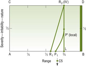
Figure A3.1 Exact sagittal posteroanterior movement, thumbs contacting each of C5's bifid spinous processes
2. When the sagittal posteroanterior movement is emphasized onto the right bifid process the diagram changes in its pain response and is closer to being ‘comparable’ than in (1) above (Figure A3.2).
3. When the contact point is changed to the lateral side of the left bifid process and directed 10° towards the right, a quite different response results (Figure A3.3). Obviously this test movement is insignificant compared with the preceding two tests.
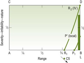
Figure A3.3 Sagittal posteroanterior movement, contact point on lateral side of left bifid spinous process of C5 and directed 10° to the right
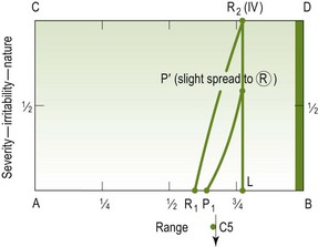
4. If the examination has been carried out in the sequence represented here, the thought may be: ‘Well, pushing on the right bifid process is the most limited movement so far, and the pain response does produce some spread of pain to the supraspinous fossa. I wonder what the pain response will be if I move my contact point to the lateral side of the right bifid process and incline the PA say 20° towards the left? (Figure A3.4). This pain response is much more comparable with his symptoms, and the movement is both stiffer and has a more similar behaviour to that of the pain than have any of the preceding movements.
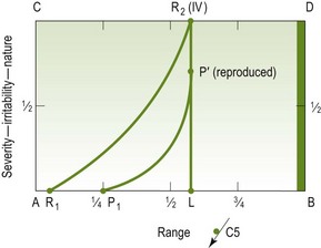
Figure A3.4
5. ‘I wonder if this is sufficiently comparable to be used as the treatment technique? I think I’ll just try adding a bit of caudad inclination through the same contact point.' (Figure A3.5). This pain response, being such a clear ‘reproduced pain’, is very favourable. Another element indicating good comparability with the patient's symptoms is the similarity of the behaviour of the resistance element to the pain element.
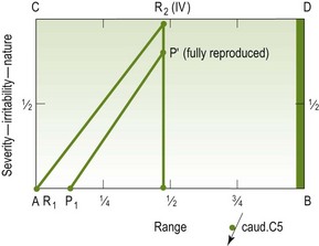
Figure A3.5
This discussion can be carried one stage further, but in a somewhat different direction. If the manipulative physiotherapist chooses to use her thumb palpation movement as her treatment technique, she has to choose between the following:
1. Avoiding the patient's pain and therefore using Figure A3.3 as the treatment technique.
2. Reproducing his symptoms and therefore using Figure A3.5.
3. Taking a reasonably safe pathway by using Figure A3.4 but doing it as a grade IV movement, or even grade IV, so that a lesser degree of pain is provoked.
Sagittal posteroanterior movements in combined positions
Tip
Posteroanterior movements in combined positions are valuable as a means of finding the movement which provokes the patient's symptoms. This can then be used as a treatment technique or progression of treatment.
The value of combined movements in examination and treatment has been emphasized in this edition. Imagine a patient who has left suprascapular symptoms that are provoked by compressing type movements, such as extension, lateral flexion left, rotation left, and central posteroanterior movements on the left articular pillar of C5:
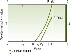
1. If the central posteroanterior movements are performed with the patient's head straight, the movement diagram may be as in Figure A3.6.
2. If the same sagittal posteroanterior movement is performed with the head rotated to the left, the diagram will be different, as shown in Figure A3.7.
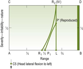
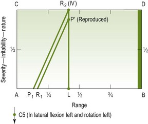
Figure A3.7 The same movements as in Figure A3.6, with head in lateral flexion to the left and rotation to the left
3. Sagittal posteroanterior movements performed with the head in lateral flexion to the left may have the movement diagram shown in Figure A3.7.
4. If the patient's head is first laterally flexed to the left and then while in this position is rotated to the left, posteroanterior movements in this combination might be as shown in Figure A3.8.
Because the computations are endless, the manipulative physiotherapist should be aware of the possibilities available to her and be capable of exploiting them if progress is not up to the expectations.
Diagrams of different movements on a patient with one disorder
Tip
To draw diagrams for different movement directions in a patient with one disorder will help to determine which of these directions is likely to be more effective as a treatment technique. Furthermore, reassessment will determine the relationship between the patient's signs and symptoms and the movement diagram.
When examining a patient's movements, there may be three main movements that provoke his (say) left mid-cervical pain. Assume that the movements are cervical rotation to the left, extension, and posteroanterior unilateral vertebral pressure on the left side of C3. The movement diagrams of each movement might be as in Figure A3.9.
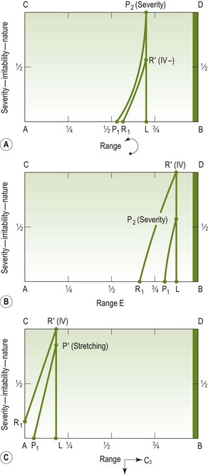
Figure A3.9 Movements provoking left mid-cervical pain. (A) Cervical rotation to the left. (B) Extension. (C) Posteroanterior unilateral vertebral pressure on left side of C3 (4 mm)
The three movement diagrams are different from each other, and seeing that they are different helps in determining which will be used (if any of them are) as a treatment technique. Also, if one is chosen, and it is successful, it would be hoped that all three diagrams would show the same kind of improvement. If, however, two of them did improve and the third did not, and also if the patient did not feel he was getting better, then perhaps the unchanged movement diagram would then be used as the treatment technique.
There is one other important aspect to bear in mind. As well as the three diagrams depicted, cervical rotation to the right might prove a useful diagram, and be useful as a treatment technique (Figure A3.10).
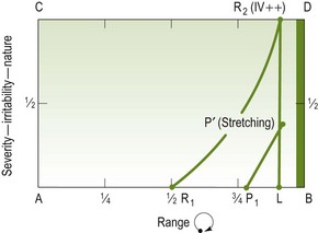
Figure A3.10 Cervical rotation to the right in the same patient as in Figure A3.9
Figures A3.9 and A3.10 are related to the standard physiological and accessory movements. It becomes more complicated when combined movements are introduced. However, when combined movements are used as part of the examination, diagrams can be used for them in the same way as described earlier in this appendix.