Biomechanical Basis of Extraction Space Closure
Madhur Upadhyay, Sumit Yadav, Ravindra Nanda
Tooth movement to close space is one of the most desired goals of orthodontic treatment. For years, orthodontists have searched for an efficient force system that can work quickly, accurately, and effectively to close extraction spaces. Orthodontic tooth movement is the result of the controlled application of mechanical forces to the teeth and periodontium. The stimulus provided by activated orthodontic appliances provides the necessary mechanical force to elicit a biological response. This perturbation temporarily disrupts the physiological equilibrium of the dentofacial complex and causes tooth movement in the direction of the net force, resulting in the closure of space.
To carry out such movements, orthodontic tools should be chosen on the basis of the biological responses of the periodontium surrounding the teeth (not yet an exact science) and their biomechanical properties as well as the appliances being used to move them (a much more exact science), rather than on the basis of anecdotal reports of success (since failures are rarely described). Therefore in this chapter we refrain from showing many clinical cases (which many orthodontists have in plenty) and instead describe the science behind orthodontic space closure.
Fundamentals of Space Closure
Before embarking on the details of the mechanics involved in space closure it is important to comprehensively analyze the basic tenets of the approach to this orthodontic problem.
The Basics
In space closure the objective is simple: to bring together opposing teeth or segments of teeth by applying a force between them. This force is usually applied on the bracket attached to the crown of the teeth (Fig. 6-1) and is occlusal and buccal to the center of resistance (CRES) of the units experiencing the force. This generates moments (moment due to force, or MF), which cause tipping and rotation of the teeth in the direction of the applied force. The clinical observation of the amount of tipping and rotation will depend on the amount of space closure. A greater amount of space closure will yield greater degrees of side effects. The amount of space requiring correction can vary depending on the severity. Less than 2-mm of spacing can be categorized as minor, greater than 2-mm but less than 4-mm is moderate, while anything greater than 4-mm is severe. Large spaces need good anchorage control over the desired tooth movement (i.e., effectively managing the unwanted moments [causing tipping and rotation] created during space closure).
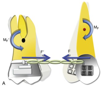
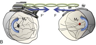
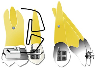
Figure 6-1 Basic dynamics of space closure. A, The magnitude of force for both teeth is equal (F = F′) but the moment due to force (MF) is not necessarily equal (MF ≠ MF′). For the definition of MF, see Chapter 4. B, Occlusal perspective of the same. Tipping will occur in all planes of space.
With efficient mechanical appliances and sound application of the fundamentals learned in Chapter 4, almost any desired tooth movement can be obtained. In a nutshell, the nature of tooth movement can be controlled by applying a counteracting moment (MC) to the MF. In Figure 6-1, the tipping showed can be controlled by this MC. The easiest way to generate this MC is to place a straight wire in the tipped brackets (Fig. 6-2). This ratio of moment to force (MC/F ratio) at the orthodontic bracket can bring about various types of tooth movement. However, the type of tooth movement seen during space closure also depends on the tooth and the objectives of the overall treatment. For example, canines and molars usually need to be translated while the anterior teeth or incisors can do well with simple tipping. Root movement is frequently required for final alignment of the roots, especially during finishing. All these movements require different MC/F ratios as we will see in the next section.
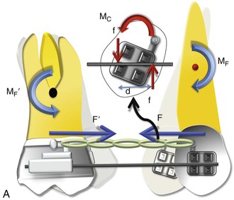
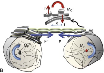
Figure 6-2 Mechanics of uprighting a tipped tooth. A, A simple way to generate a counteracting moment (MC) is to place a straight wire in tipped brackets. The interaction of the MC and moment due to force (MF), or the moment to force (M/F) ratio, dictates the nature of tooth movement. Note that MF = F × distance from the center of resistance (CRES), while MC = F × d (distance between the two couple forces). B, Occlusal perspective of the same. Uprighting will occur due to the wire-bracket interaction. Thus the quality of tooth movement is an interplay of moment due to a couple (in red) and the force (in blue).
Moment to Force (M/F) Ratio
The M/F ratio is a good way to describe or predict the quality of tooth movement. In the literature it has been stated that an M/F ratio of 5 : 1 is required for tipping, of 7 : 1 is required for controlled tipping, of 10 : 1 is required for translation, and of 12 : 1 is required for root correction. However, these ratios cannot be applied universally for all teeth and in all situations. For example, for translation the ratio of 10 : 1 applies for a single rooted tooth where the distance of the bracket or the point of force application is 10-mm from the CRES of the tooth and the amount of force applied is 100 g. A more general way of defining M/F ratio for tooth movement should follow a qualitative approach, not a quantitative approach. High, moderate, and low M/F ratios can do this aptly.
As seen in Chapter 4 and in Figure 6-1, a single force applied at the bracket of a tooth will produce uncontrolled tipping with the center of rotation (CROT) slightly apical to the CRES. Now if a counterbalancing moment (MC) is applied and is high enough, it can perhaps negate the MF. (Note: In Figure 6-2, the MC is generated when the opposite ends and corners of the bracket contact the wire placed in the slot.) This will result in translation. A further increase will cause root movement into the space. At these relatively high M/F ratios, stresses reportedly distribute more evenly through the entire root with minimal changes in the mechanical properties during activation; this reduces injuries to teeth and surrounding tissues. A moderate MC will only partially oppose the MF, leading to controlled tipping with the apex remaining stationary. It is apparent from this discussion that regulating the MC/F (or MC/MF) ratio is key in producing different types of tooth movement for space closure.
However, it is important to mention that the nature of tooth movement can also be regulated by varying the point of force application (see Chapter 4 for a detailed discussion on this).
Anchorage
As discussed, space closure involves the gradual closure of space between two teeth or two segments of teeth when one or both move toward each other. Depending on the needs of the patient, one set of teeth or one tooth can be classified as the active unit while the other is classified as the passive or reactive unit. These two units have completely different roles during tooth movement. The active unit undergoes the majority of the movement while the passive unit resists any kind of movement and provides the resistance necessary to facilitate the movement of the active unit, thereby serving as an anchorage. Therefore anchorage can be defined as the resistance offered by the passive unit toward any type of unwanted movement when the active unit is undergoing the desired movement. The set of teeth that offers this anchorage or resistance is also called the “anchorage unit.” The anchorage setup for different situations can be broadly classified into four types (Fig. 6-3):
1. If all movement is seen in the active unit and absolutely no movement is seen in the passive unit, it is called absolute anchorage. Clinically, it is very difficult to obtain absolute anchorage. However, with the development of skeletal based anchorage systems in recent years, significant strides have been made towards achieving absolute anchorage.
2. If the active unit undergoes the majority of the movement and there is minimal movement of the passive unit, it is called Group A anchorage. This is also known as maximum or high anchorage.
3. If the movement is shared equally among the active and passive units, it is called Group B anchorage. This is also known as moderate or medium anchorage.
4. If the majority of movement is seen in the passive unit, it is called Group C anchorage. This is also known as low or minimal anchorage. Needless to say, when there is Group C anchorage for a particular set of teeth, it means there is Group A anchorage for the other set. Thus in many ways the term Group C anchorage is redundant.
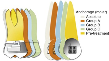
Figure 6-3 Classification of anchorage (for an approximate space of 8 mm). Each increment represents 2 mm. To calculate the movement of a particular shaded tooth, add all increments preceding it. For example, for the green color the molar has move forward by 2 (orange) + 2 (blue) + 2 (green) = 6 mm, while the canine has moved forward only 2 mm. Therefore this represents a group C situation for the canine and a group A situation for the molar.
One of the easiest ways to generate Group A anchorage is by creating a high M/F ratio. In rare situations anchorage might even go beyond absolute anchorage and you might notice a net “anchorage gain.” For example, during en masse retraction of the anterior teeth, the incisors and the molar both can move distally. This sometimes occurs when skeletal anchorage is used to reinforce anchorage.
Methods of Space Closure
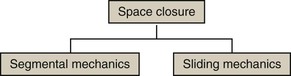
Space closure can be accomplished by adopting friction-based mechanics, often called “sliding mechanics,” or without friction, also known as “segmental mechanics” (Fig. 6-4).
Segmental Mechanics
The basic premise of this concept is that all teeth in the upper or lower arch are not connected to each other by a continuous wire but are divided into discrete groups or segments. This segmentation is done on the basis of the role the teeth serve in space closure (i.e., which group of teeth is supposed to move and which is not). The groups are consolidated into segments: active and passive (for anchorage). Force is then applied between these segments to close the extraction space. Since the segments are not connected by a straight wire (i.e., the teeth are not moving on a wire), this is also referred to as “frictionless mechanics.” Closure of space is usually done by loops (potential energy–loaded springs) constructed from regular orthodontic archwires. All closing loops have specific mechanical properties (i.e., response to mechanical forces). Clinicians need to know these properties in order to use them optimally to move teeth or groups of teeth in predetermined directions. In the next section we will elaborate on these properties.
The main mechanical loop properties are the M/F ratio, load and deflection ratios, and the vertical force created. Among these, the M/F ratio can be considered the most significant because it is related to the type of tooth movement.
Concept of Differential Moments
Typically, for severe space closure scenarios a high M/F ratio loop is desirable, while minor spaces can be dealt with loops expressing a low M/F ratio. This is because with more space, teeth have a tendency to show more tipping. Therefore a high M/F ratio will ensure that they remain upright through the space closure.
For example, during incisor retraction the high M/F ratio for the posterior teeth will encourage anchorage preservation as it resists any tipping into the extraction space. In fact, a large posterior moment can cause distal crown movement, thereby opening up more extraction space. On the other hand, the low M/F ratio for the incisors encourages tipping. Simply described, methods using differential M/F ratios may be represented mathematically by the inequality MCp/F ≠ MCa/F and MCp/F ≫ MCa/F (here, a indicates anterior and p indicates posterior).
The application of such unequal moments must also comply with the laws of equilibrium discussed in Chapter 4. Because the moments created at each end of the loop or spring are unequal, the total force system must have additional effects. Vertical forces (intrusive and extrusive) are therefore also acting on the two segments. The magnitude of the vertical force depends on the difference between the two moments and the distance between the two segments.
In contemporary orthodontics, many closing loop shapes are being used, such as vertical or teardrop loops, T-loops, L-loops, Gjessing springs, and others.1–6 These loop types can be further modified by adding a coil, altering the height, tipping the vertical legs (to increase the MC), and so on.
Optimizing Loops for Space Closure: How Loop Design Affects the M/F Ratios
Researchers and clinicians have tried to design and refine loop geometry to obtain the highest M/F ratios possible, with the primary objective of reinforcing anchorage. Mechanical properties of closing loops depend on many factors, such as loop height, width, shape, and position; wire material; cross-sectional dimensions; and so on.4,5,7–9 Let's look into some of these factors in detail.
Loop Height
Loop height, in particular, affects the M/F ratio considerably. As the loop height increases, the M/F ratio increases. Unfortunately, no loop can reach a M/F ratio greater than its height. Burstone and Koenig7 reported that a 6-mm-high vertical loop had a M/F ratio of approximately 2 whereas a 10-mm-high vertical loop had a M/F ratio of about 4 for a 7-mm horizontal loop length. For a T-loop, as the gingival horizontal length increases, the M/F ratio increases as well to an upper limit and then levels off. Loop length and coil (helix) have only minor effects on the M/F ratio. There is a limit to which the height of a loop can be extended as it starts creating both bending difficulties and inconvenience to the patient when inserted in the mouth.
Loop Shape
The shape of a loop is another important factor to adjust the mechanical properties. The M/F ratio generated by T-loops is higher than that of vertical loops with the same loop height.7,9 A so-called Opus loop introduced by Siatkowski4,5 has an L shape with a helix in the apical portion of the L to increase the M/F ratio. Siatkowski reported that the Opus 70 loop, with the vertical legs tipped 70 degrees backward, had a M/F ratio as high as 8.7 mm, which is much higher than can be obtained by vertical loops or T-loops with similar dimensions. However, L-loops with similar dimensions as the Opus loop have given the highest M/F ratios to date (Fig. 6-5).10
Loop Placement
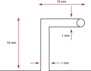
The final position of a loop between the active and passive units can significantly modify the M/F ratio.8,11,12 In fact, this is the primary mechanism by which differential moments are created for space closure. This is known as “off-centered positioning of the loop.” Higher moment is produced at the bracket closer to the loop. This principle is directly borrowed from the V-bend principles discussed in Chapter 4. Off-centered V-bends produce a greater moment on the closest tooth. As the loop is activated by horizontal activation (discussed below), the two legs of the loop form an angle with each other (Fig. 6-6). This angle can be further accentuated by placing bends in the loop, thereby increasing the differences in the M/F ratios between the two segments of teeth.
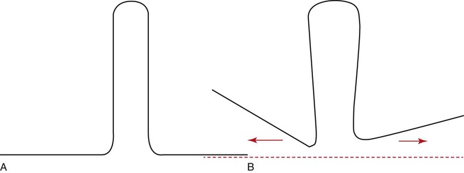
Figure 6-6 A, A typical vertical loop. B, After horizontal activation the two legs are at an angle to each other. This angulation creates a moment opposite in direction to that created by the moment due to a force (MF).
Let us now examine how loop placement and the preactivation bends are clinically used to control space closure. Two clinical situations are presented: canine retraction and incisors retraction.
Segmental Mechanics for Space Closure
Canine Retraction
Canine retraction is the movement of the canine in a distal direction from a position close to the lateral incisors to a position next to the premolar along the gentle curvature of the arch.
Setup.
Let us consider that there is an anteroposterior space of approximately 8-mm to be closed distal to the canine. Before space closure can be initiated with a loop, it is important to ensure that the teeth or segments of teeth to be incorporated for tooth movement or anchorage are adequately aligned so that a 0.021-inch × 0.025-inch stainless steel wire (in a 0.022-inch slot bracket) can be used to hold them as separate units. The only link between the two units should be the loop.
Preactivation of the Loop (Figs. 6-7 and 6-8).
Before the loop can be inserted into the extraction space, certain “preactivation bends” must be placed so that the loop gives a V- or U-shaped outline overall. Remember from Chapter 4 that the mechanics of a loop can be worked out by understanding the geometries described. The preactivation bends are also known as the alpha bend (anterior curvature) and beta bend (posterior curvature). The bends are necessary to create the moment (MC) that will counteract the moment generated by the force (MF). The greater the degree of bend, the higher the MC generated. Also, higher moment is created on the tooth closer to the loop (see discussion of off-centered “V” bends in Chapter 4).

Activation of the Loop.
The final activation of the loop is done only when it is placed in the bracket slots. The wire is pulled distally through the posterior tube and cinched. The amount of distal pull is guided by the amount of space to be closed. For an 8-mm extraction space, ideally 8-mm of activation is good. This activation step is necessary to generate the required force and MF for space closure.
Once the loop has been activated and placed at the desired location, tooth movement is initiated by “deactivation” of the loop. Space closure with loops progresses via three distinct phases, which can be delineated comprehensively at both the theoretical and the clinical level. The quality and nature of tooth movement is primarily determined by the interaction of the MF and MC generated as the teeth move toward each other.
Phase I (Tipping).
In the initial phases of retraction the spring is fully activated and therefore the force is high, resulting in a high moment (MF = F × d, where d is the distance between the point of application of force and the CRES of the canine). This condition results in a MC/MF ratio <1, placing the CROT of the canine close to the apex. The canine therefore shows considerable crown movement with minimal root movement (Fig. 6-9, A). This phase represents a classical example of “differential moments,” described earlier in the chapter. Due to the nature of movement of the canine versus the molar (crown tipping of canine versus root tipping of molar) the anchorage demand on the molars is minimal, or in other words the chance of “anchor loss” is minimal. Hence, the anchorage demand from the molar is less. It is important to remember that if the operator does not place enough preactivation bends on the loop, this phase might show uncontrolled tipping of the canine with rapid dumping of the canine.
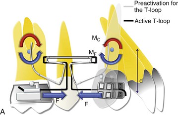
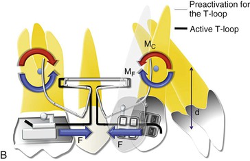
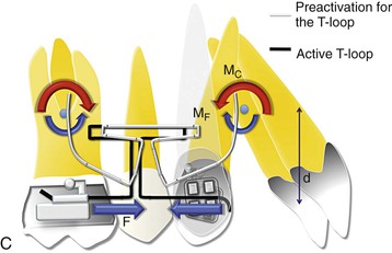
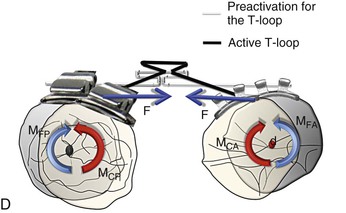
Figure 6-9 Space closure with loops. A, Phase I of loop deactivation (simple tipping). As MF ≫> MC, there is minimal root movement with more crown movement. MF = F × d. Note: The stabilizing wires for the passive segments are not shown. B, Phase II of loop deactivation (translation). As MF = MC, there is equal crown and root movement. Therefore the canine is undergoing bodily movement. (Remember that such a situation rarely exists where the moments are perfectly balanced.) C, Phase III of loop deactivation (root movement). As MC ≫> MF, there is minimal crown movement and more root movement. D, Occlusal perspective of the same. The V-bend placed in the T-loop will generate the counteracting moment or moment due to a couple (MC) to oppose the rotation of the molar and canine. To have no rotation during retraction, MF = MC.
Phase II (Translation).
As the canine is distalized and the distance between the two attachments decreases, the force levels drop. This causes a reduction in the MF as well. At some point, MC = MF (MC/MF = 1). Such a situation will place the CROT at infinity. At this stage the canine is translating as the moments are cancelled out (Fig. 6-9, B). Here, both the molar and the canine tend to translate. However, it is important to remember that this will not happen at the same time for the two teeth as the MF values are different for the canine and molar. Also, the probability of anchor loss in this phase is high, because there is no net moment on the molar to reinforce anchorage and there is greater anchorage demand on the molar due to canine translation.
Phase III (Root Movement).
The force levels continue to drop and so does the MF but the MC drop is not that significant (as it depends on the elasticity of the wire). Therefore, at this stage the MC/MF ratio is >1, thereby reversing the net moment (Fig. 6-9, C). This results in more root movement than crown movement, paving the way for root correction (as in phase I the canine had tipped). The canine therefore is undergoing root tipping or root uprighting while the molar shows predominantly crown tipping. Therefore this phase is vulnerable to showing some molar mesial movement (anchor loss). Anchorage reinforcement may be needed.
Note that for ease of understanding, the vertical forces generated due to the unequal moments have not been shown in Figure 6-9. Also, all phases will be similar to the one described above from an occlusal perspective as well (Fig. 6-9, D).
It is important to remember that the MC/MF ratio is responsible for optimizing the quality of canine movement while the force is responsible for the actual distal movement. Once the canine has undergone all of these phases of movement, complete deactivation of the loop has occurred. It now needs to be reactivated and then the canine will undergo the same kind of movement described above. Depending on the initial position of the canine a clinician might not want the canine to go through all three phases of distalization. For example, in crowded arches the canine is often mesially tipped and a simple uprighting of the canine is more than enough to close the extraction space (Fig. 6-10). Therefore, the spring can be removed once it has completed phase I.
Incisor Retraction
Retraction of incisors will proceed in a similar way as that described above. However, from an anchorage perspective it places less demand on the posterior teeth or the anchor units. This can be largely attributed to the nature of movement desired for the incisors. Usually the incisors have to undergo only tipping for extraction space closure, with minimal translation and in only rare circumstances root uprighting. In terms of mechanics it means placing a high moment (MC) on the posterior/anchor unit while considerably less moment is needed for the incisors. Therefore phase I is generally more than sufficient to complete the space closure process when incisors are being retracted. In terms of loop mechanics, more moment (MC) must be created for the posterior unit (MCp ≫> MCa). This can easily be done by using any of the techniques described previously but the most common and easiest approach is the offset placement of the loop (Figs. 6-11 and 6-12). In this case the offset will be closer to the posterior segment. The moments and the forces created will follow the same rules as the V-bends discussed in Chapter 4.

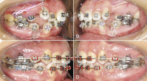
Figure 6-11 A mushroom loop for en masse retraction of the incisor and canine. Note the offset placement of the loop to preserve anchorage of the posterior segment. A–C, At the beginning of retraction. D–F, After space closure.
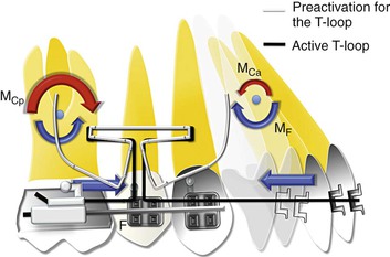
Figure 6-12 Mechanics of incisor retraction (simple tipping). As MF ≫> MC , there is minimal root movement and more crown movement. Note that the loop is placed toward the posterior segment to create a greater moment (MCp ≫> MCa) on it than on the anterior teeth.
From a theoretical standpoint segmental mechanics is arguably the most efficient way to move teeth. However, due to its overreliance on the operator's skills in terms of loop fabrication, positioning, preactivation bends, activation, etc., segmental mechanics is highly technique sensitive. The clinician should be extremely careful in using this technique. On the other hand, sliding mechanics is less sensitive to technique but follows the same principles described above for space closure.
Sliding Mechanics
Ever since the Andrews straight-wire appliance13 was introduced there has been a gradual but paradigm shift from closing loop mechanics to sliding mechanics. The objective is simple: to create a force system that can work efficiently and shorten the orthodontic treatment period. Sliding mechanics contributes to achieving more control during space closure (i.e., fewer side effects such as tipping and rotation), improving patient comfort, and preventing excessive force application.
By definition, in sliding mechanics force is applied between two teeth or segments of teeth such that they move or slide on a straight wire inserted in the respective brackets of the two segments so that a significant amount of friction is generated between the wire and the bracket surfaces. With the closing loop mechanics, activated loop create force only at the bracket level, and control is created by generating moments (via preactivation bends) whereas in sliding mechanics, retraction forces can be transferred to any height level on a power arm to move the teeth in a preprogrammed direction (e.g., controlled tipping, translation).
Two methods have been used for extraction space closure. The first method is two-step retraction, which involves canine retraction followed by incisor retraction. The second method is “en masse” retraction of the six anterior teeth.
Canine Retraction
A continuous archwire engages the brackets affixed to the facial surfaces of the teeth. In particular, the wire within the bracket attached to the canine crown and supported at neighboring posterior and perhaps anterior dental sites is intended to guide the tooth during its distal displacement.
To begin, let us assume that the teeth have been leveled and aligned to a degree that the archwire chosen for retraction sits passively through the bracket slots. Typically, for canine retraction the method used to provide the distal force (F) is a spring or an elastomeric element (module, chain, O-ring, or tied thread). Orthodontic tooth movement occurs as a result of mechanical force exerted on the crown and maintained there over some finite period of time. It is important to mention that this distal driving force will typically decrease with time if an elastomeric element is involved.
For the ease of understanding the details involved in this seemingly continuous and smooth process, we have divided it into four distinct phases as we did for segmental mechanics in the previous section. The beginning and end of each phase are defined by four instantaneous views of the mechanics involved. Each phase represents a characteristic movement pattern distinct from the other three. Each part of Figure 6-13 represents an instant of time during the retraction process. The force system shown is exerted on (not by) the canine; accordingly, the symbols for the delivered force and the couple partially represent their displacement potentials.
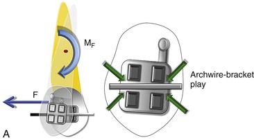
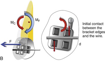
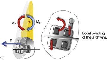
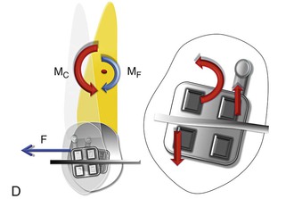
Figure 6-13 Mechanics of canine retraction with sliding mechanics. A, Phase I (the unsteady state/uncontrolled tipping). The archwire-bracket play allows for uncontrolled tipping of the canine. Note: Due to the play, no MC is generated. B, Phase II (the controlled state/controlled tipping). The archwire-bracket play no longer exists. There are signs of initial contact between the archwire and the bracket edges giving rise to MC. Here, MF ≫> MC. C, Phase III (the steady state/translation). The contact between the archwire and the bracket edges has increased, leading to an increase in the MC. Simultaneously there can be a decrease in the force levels, causing a decrease in MF. Here MF = MC. D, Phase IV (the restorative state/translation). There is a pronounced decrease in the force levels, causing a decrease in MF. Here, MF ≪ MC.
Phase I.
This is the initiation of canine retraction. A single force (F) is applied on the canine bracket in a distal direction (Fig. 6-13, A). This force produces a moment (MF) acting at the CRES of the canine, causing it to tip as it is being distalized. Since there is some degree of play between the archwire and the bracket slot, the tooth is free to tip in the mesiodistal direction in an uncontrolled manner, creating a CROT slightly apical to the CRES (from Chapter 4). This can also be referred to as the “unsteady state” of canine retraction, as it is undergoing uncontrolled tipping.
Phase II.
The canine is now tipped to the extent that the aforementioned clearance (or play) between the bracket slot and the wire has been eliminated (Fig. 6-13, B). The sketch in Figure 6-13, B depicts the canine somewhat later in time relative to Figure 6-13, A. Archwire–bracket slot contact now exists. This two-point contact by the archwire exerts a pair of parallel, equal in magnitude, noncollinear forces to form the MC. (The two forces will be of the same magnitude if the wire, because of its occluso-apical location and that of the bracket, generates no net potential to extrude or intrude the tooth.)
This MC opposes the MF, resulting in less tipping of the canine when compared to phase I. As the wire further deflects, MC continues to increase and the CROT moves to the apex of the canine, creating controlled tipping of the canine. This can also be called the “controlled state” of canine retraction. With a preangulated bracket slot the initial clearance can be zero with some local second-order rotation required to engage the wire in the slot. If this is the case, MC exists from the start of the retraction process. Also note that, as MC appears, some frictional resistance to these sliding mechanics arises but is assumed to be small. The magnitude of MC is, principally, directly related to the local bending of the guiding archwire at the canine bracket site and therefore is intricately associated with the wire properties, such as stiffness and resiliency. The size of MC also, to a much lesser extent, is associated with the location of the canine bracket relative to support sites mesial and distal to it.
Phase III.
As distal crown tipping continues, the magnitude of MC increases directly with the local wire bending deformation. (Presumably the archwire maintains its elasticity throughout the retraction process.) With the accompanying distal displacement of the crown and relaxation of the driving component (elastomeric) of the appliance, F decreases in magnitude. The possibility then arises that the couple to force (MC/F) ratio may be reduced to nearly equal the distance between the crown center (where the bracket is placed) and the CRES of the canine. In other words, here MC = MF. Therefore the net moment acting on the canine has decreased to zero, signifying that the CROT has migrated apically and the tipping displacement has potentially transformed into bodily movement. This mechanical configuration is shown in Figure 6-13, C. This situation can be attained either by a reduction in MF or by an increase in MC. It is important to remember that the relative values matter more than the absolute values. If this delicate balance of forces and moments is maintained, the canine will continue translating. This phase is also called the “steady state.” However, this phase is at best only a theoretical possibility and for all practical reasons is impossible to attain.
Phase IV.
For the canine distalization to enter this phase it must be assumed that the distal driving force is undergoing a constant decay through the retraction process. As discussed, the bodily displacement format may exist only momentarily. As the F decreases, so does the MF; however, because of the angulated bracket and the local bending of the archwire, the MC does not decrease as readily as the MF. Therefore in this phase MC ≫ MF and the MC/F ratio is greater than in the previous phase (Fig. 6-13, D). This results in restoration of the axial inclination of the canine (uprighting or root correction). This can be called the “restorative state” of canine retraction and can be clinically referred to as the second-order torquing of the canine. A tremendous amount of frictional force is generated at the wire-bracket interface, resulting in the relocation of the CROT gingival to the CRES anywhere between the bracket and the CRES. Remember that if the distal force does not show decay, this phase is never reached; instead, the canine might be relegated to just the first two phases (i.e., tipping only).
In a similar evaluation form, the occlusal view, the bracket is labial to the CRES and hence a distal force will again create a MF that will rotate the canine distally inward. This will be phase I (the unsteady state). Until the point play exists between the wire and the bracket from an occlusal view, the canine is free to rotate. During phase II (the controlled state) the archwire begins to deflect as the diagonally opposite ends of the bracket contact the archwire. A MC is generated, which minimizes the MF. In phase III (the steady state) the moments are equally balanced and there is no change in the position of the canine from an occlusal perspective. In phase IV (the restorative state) the rotated canine starts derotating because MC exceeds MF in magnitude.
Force Transmitted to the Anchor Teeth
The setup for canine retraction described above is a “friction-based” system in which the canine, through the application of a force, is made to slide distally guided by a continuous archwire that connects the incisors to the molars. The canine is the link between the posterior teeth (premolars and molars) and anterior teeth (incisors). Therefore it is not difficult to imagine that any change in its position might have a direct effect on the incisors and the molars. Let us consider carefully what those side effects might be.
Effect of Canine Retraction on the Incisors.
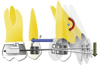
An implicit advantage of canine retraction on a continuous arch system lies in limiting the possibility of unpredicted canine movement (e.g., flaring or rotation). Despite the advantages of sliding mechanics, canine retraction does present its own set of problems. When pure forces generated from springs or elastics are induced at the canine, especially when an archwire with a low load-deflection rate is being used or the force levels are too high, the wire tends to deform with undesirable side effects on other teeth (Fig. 6-14). Due to the tipping of the canine described in phases I to III, a constant stress is created on the wire, resulting in its elastic deflection. This deflection of the wire creates an extrusive force on the incisors and a moment that tends to cause lingual tipping. This tendency for archwire deflection can be reduced by using higher stiffness archwires and/or lighter forces for retraction. Auxiliary archwires, such as an overlay intrusion arch or cantilever springs, can also help to minimize the assumed deflection of the archwire.
Effect of Canine Retraction on the Molars.
According to Newton's Third Law of Motion, the retraction force on the canine should exert the same force on the molar. This force will create a moment on the molar, causing it to tip mesially. The molar will then undergo all four phases of mesialization as described for the canine. However, the degree of movement may vary depending on the surrounding bone, tooth characteristics, number of additional teeth ligated to the molar, etc. An important side effect seen quite often clinically, especially when heavier forces are used, is the presence of a lateral open bite due to simultaneous tipping of the canine and molar crowns with no root correction. This can largely be attributed to the increased levels of retraction forces preventing the tooth from entering into phase III or phase IV of sliding movement.
Incisor Retraction
During space closure the incisors also follow the same phases of retraction as the canine. The dominant phases in incisor retraction are phases I and II (i.e., tipping).
Although clinically incisor retraction is similar to canine retraction, at the mechanical level there are a few differences. When tipped back, the bracket of a canine undergoes a second-order interaction with the archwire; in contrast, due to its position an incisor bracket has a third-order interaction. This third-order interaction lends itself to a greater degree of play compared to the second-order interaction of the canine. Therefore the dominant phases in incisor retraction are phases I and II (i.e., tipping), as the greater degree of play allows for more tipping. The questions that arise in such a situation are: What if we do not want this tipping? Or what if we are looking for more control on incisor retraction from the initiation of retraction? To achieve these goals we want to introduce an MC in the first phase of retraction.
Some common ways of doing this are:
1. Bending the wire (V-bend, as discussed in Chapter 4)
2. Placing a curve in the main archwire
Another method of minimizing the tipping movement of the incisors and canine is by decreasing the MF produced without compromising the magnitude of force. This can be achieved by changing the point of force application relative to the CRES of the teeth. This can be easily achieved by using a “power arm” (Fig. 6-15). The effects of such mechanics on the incisor tooth are described in detail in Chapter 4.
Mini-Implant–Driven Mechanics of Tooth Movement
Why Do We Need Mini-Implants for Space Closure?
The extraction of premolars and anterior teeth retraction is generally indicated when there is obvious protrusion of teeth and there is a strong esthetic need. While retracting anterior teeth in a full cusp Class II malocclusion or in a Class I bialveolar dental protrusion case, anchorage control assumes profound importance because maintaining the posterior segment in place becomes very critical. A loss in molar anchorage can not only compromise correction of the anteroposterior discrepancy, but also affect the overall vertical dimension of the face. The application of mini-implant–supported anchorage can circumvent the anchorage issues in such situations, maintaining a Class II molar relationship while establishing a Class I canine relationship for esthetics and functional guidance.
Where to Use Mini-Implants
Mini-implants (MIs) serve as anchorage units in situations where there is a need for absolute anchorage.14–18 They are used to generate a constant and predictable force system, so that accurate and precise movement of the active units can be achieved without the concern about the possibility of anchor loss. In other words, MIs help in eliminating the element of unpredictability that is associated with the traditional anchorage units (usually the posterior teeth), thereby making the orthodontist completely in charge of the tooth movement desired.
Basic Principles of Mini-Implant Use
To maximize the potential of MIs, it is crucial to understand the underlying mechanics behind the force application from an MI to the active unit or teeth. This section details the fundamental biomechanical principles involved in the usage of such devices and their practical applications.
Here is a simple example to elucidate the need to understand the mechanics involved with MIs. When using conventional mechanics, force application is usually parallel to the occlusal plane and hence we are required to deal with the force only in one plane. However, because MIs are usually placed apical to the occlusal plane into the bone between the roots of teeth, force applied is always at an angle (Fig. 6-16). (Note: The preferred location for MI placement is between the roots of the second premolars and first molars close to the mucogingival junction. Care should be taken that the MIs are not inserted too far apically in the movable mucosa, since this can lead to implant failure due to persistent inflammation around the MI site.) This angulated force lends itself to be broken into two components (by the law of vector resolution, discussed in Chapter 4): a horizontal retractive force (r) and a vertical intrusive force (i). The force applied with MIs in such a setup is also closer to the CRES of the anterior unit. Therefore, the MF with MIs is significantly less than with conventional mechanics. Clinically it means there is less tendency for the teeth to tip.

Figure 6-16 The vector of force varies between conventional mechanics (FO) and implant-based mechanics (FI) for space closure. Biomechanical design of the force system involved during en masse retraction of the anterior teeth with implants. Here, F ≫ r > i, where F is total force, i is intrusive component, and r is retractive component. Also, the moment created by the implant is significantly less than that created by conventional mechanics. (Force application with implants is closer to the CRES and M = F × distance to the CRES.)
In addition, with conventional mechanics the molars or posterior segments usually serve as the anchor unit, with the rest of the arch serving as the active unit. The force system is therefore differentially expressed in the active unit and the anchorage or passive unit within the same arch. In contrast, when MIs are incorporated as the third counterpart, selective movement of the anterior and posterior segments is possible. Precise planning for the amount of the desired tooth movement is thus a prerequisite before active treatment can be initiated.
Mechanics of Space Closure with Mini-Implants
According to Figure 6-16 (a pictorial description of the initial force system for en masse retraction), the force (F) exerted by the nickel-titanium (Ni-Ti) coil springs (bilaterally) has two distinct components: a larger and predominantly retractive force (r) and a smaller intrusive force (i), causing en masse retraction and some intrusion of the anterior teeth. Additionally, there is a clockwise moment (M) on the anterior segment as the total force passes below the estimated CRES of the anterior teeth. This moment causes the anterior teeth to tip. The degree of tipping will be regulated by the thickness and stiffness of the archwire. For example, a 0.017-inch × 0.025-inch stainless steel archwire has approximately 12 to 14 degrees of play in a 0.022-inch slot, assuming that the wire is completely passive when retraction starts, while a 0.016-inch × 0.022-inch stainless steel archwire has 16 to 18 degrees of play (Fig. 6-17). Therefore the latter will show greater amounts of tipping and a prolonged phase I and phase II of retraction compared to the former. A clinician should judiciously select the archwire for space closure.
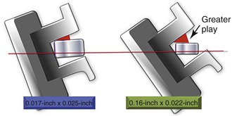
Figure 6-17 The amount of play between the bracket and archwire depends on the size of the archwire.
For example, if the anterior teeth are flared at the beginning, more tipping is required; hence a thicker wire will be of limited use, as the effective play will be less. If instead the teeth are upright and there is a need for more control on the incisors, a thicker wire should be the choice (Fig. 6-18). As discussed, another method of obtaining control over the incisors during space closure is the use of power arms. This can be employed with implants as well (Fig. 6-19). For a complete list of approximate play for different archwire sizes, refer to Table 6-1.
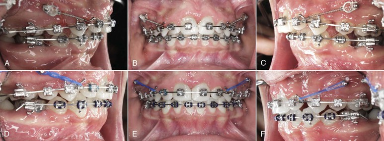
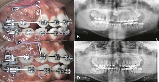
Figure 6-18 En masse space closure with mini-implant–supported anchorage. A–C, The incisors were upright at the beginning of space closure, so a 0.019-inch × 0.025-inch stainless steel archwire was used. D–F, After space closure. The axial inclination of the incisors was maintained to a large extent.
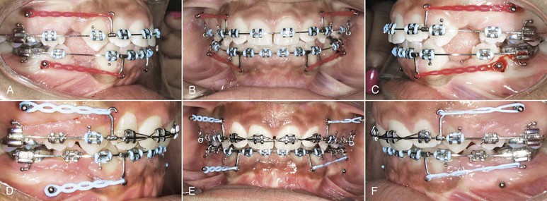
TABLE 6-1
Amount of Wire Bracket Play in the Third Order for Different Archwire Sizes
| Archwire Size (inches) (for stainless steel) | Amount of Play (degrees) |
| 0.016 × 0.022 | 16–18 |
| 0.017 × 0.025 | 13–14 |
| 0.019 × 0.025 | 6–8 |
| 0.021 × 0.025 | 2–3 |
Once the anterior teeth have tipped by the amount of play available between the bracket slot and the wire (clearance), no further tipping occurs, as the brackets lock onto the wire in that position and a counteracting MC is generated, as discussed earlier. A bodily movement of the anterior teeth can be expected if the retractive force is continued but biological limitations can also play a decisive role.
After the extraction spaces are closed, contact between the canine and the second premolar is established. From this point on, further continuation of the retraction results in transmission of the total force to the posterior segments through the interdental contacts, producing a distal and intrusive force on the posterior teeth and a moment (M) on the entire arch (Fig. 6-20). These mechanics has often been employed to correct Class II molar relationships without extractions.
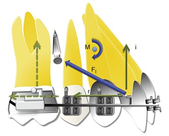
Figure 6-20 Biomechanical design for the force system involved after space closure. Retraction of the upper anterior teeth is still in progress. Note the increase in the angulation of the total force relative to the occlusal plane. (Here, FI ≫ r ≈ i.) Such a mechanical configuration has important implications for vertical control and Class II correction.
The biomechanics involved during en masse retraction with MI-assisted anchorage has other advantages that are quite distinct from other conventional methods, especially in high-angle patients. One such advantage, which is quite obvious, is the fact that there is no possibility of molar mesialization or anchorage loss in such a setup, since no retractive force is being applied from the molars. Therefore it is an effective way of compensating for a Class II malocclusion with large overjet.
Summary
Space closure is the most critical aspect of orthodontics, especially in cases undergoing extraction. This chapter covers only the essential fundamentals of space closure, providing a stepping stone for further advanced reading in this area. A more detailed description involving the role of friction and archwire properties is beyond the scope of this book. Nonetheless, understanding the forces and moments involved during this procedure and their customized application for individual cases and situations can significantly enhance the outcome of treated cases.
References
1. Gjessing P. A universal retraction spring. J Clin Orthod. 1994;28:222–242.
2. Hoenigl KD, Freudenthaler J, Marcotte MR, Bantleon HP. The centered T-loop: a new way of preactivation. Am J Orthod Dentofacial Orthop. 1995;108:149–153.
3. Martins RP, Buschang PH, Gandini LG Jr. Group A T-loop for differential moment mechanics: an implant study. Am J Orthod Dentofacial Orthop. 2009;135:182–189.
4. Siatkowski RE. Continuous arch wire closing loop design, optimization, and verification: part I. Am J Orthod Dentofacial Orthop. 1997;112:393–402.
5. Siatkowski RE. Continuous arch wire closing loop design, optimization, and verification: part II. Am J Orthod Dentofacial Orthop. 1997;112:487–495.
6. Coimbra ME, Penedo ND, de Gouvea JP, Elias CN, de Souza Araujo MT, Coelho PG. Mechanical testing and finite element analysis of orthodontic teardrop loop. Am J Orthod Dentofacial Orthop. 2008;133 [188.e9–e13] .
7. Burstone CJ, Koenig HA. Optimizing anterior and canine retraction. Am J Orthod. 1976;70:1–19.
8. Faulkner MG, Fuchshuber P, Haberstock D, Mioduchowski A. A parametric study of the force/moment systems produced by T-loop retraction springs. J Biomech. 1989;22:637–647.
9. Safavi MR, Geramy A, Khezri AK. M/F ratios of four different closing loops: 3D analysis using the finite element method (FEM). Aust Orthod J. 2006;22:121–126.
10. Techalertpaisarn P, Versluis A. Mechanical properties of Opus closing loops, L-loops, and T-loops investigated with finite element analysis. Am J Orthod Dentofacial Orthop. 2013;143:675–683.
11. Kuhlberg AJ, Burstone CJ. T-loop position and anchorage control. Am J Orthod Dentofacial Orthop. 1997;112:12–18.
12. Firouz T, Kuhlberg AJ, Nanda R. Efficacy of extraction space closure by precalibrated T-springs. Inf Ortho Kiefer. 1998;30:663–674.
13. Andrews LF. Straight Wire: The Concept and Appliance. L.A. Wells Company: San Diego, CA; 1989.
14. Upadhyay M, Yadav S, Nagaraj K, Uribe F, Nanda R. Mini-implants vs fixed functional appliances for treatment of young adult Class II female patients: a prospective clinical trial. Angle Orthod. 2012;82(2):294–303.
15. Upadhyay M, Yadav S, Nanda R. Vertical dimension control during en masse retraction with mini-implant anchorage. Am J Orthod Dentofacial Orthop. 2010;138:96–108.
16. Upadhyay M, Yadav S, Nagaraj K, Patil S. Treatment effects of mini-implant for “en masse” retraction of anterior teeth in bialveolar dental protrusion cases: a randomized controlled trial. Am J Orthod Dentofacial Orthop. 2008;134:18–29.
17. Upadhyay M, Yadav S, Nagaraj K, Nanda R. Dentoskeletal and soft tissue effects of mini-implants in Class II Div 1 patients. Angle Orthod. 2009;79:240–247.
18. Upadhyay M, Yadav S, Patil S. Mini-implant anchorage for en masse retraction of maxillary anterior teeth: a clinical-cephalometric study. Am J Orthod Dentofacial Orthop. 2008;134:803–810.