Biomechanics in Orthodontics
Madhur Upadhyay, Ravindra Nanda
The physical concepts that form the foundation of orthodontic mechanics are the key to understanding how orthodontic appliances work and are critical in designing treatment methodologies and appliances. These physical concepts are not unique to orthodontics but are the elementary laws of mechanics in general. In this chapter we outline the ground rules and fundamentals that guide orthodontic tooth movement. All appliance systems reported in the past and all systems that will be reported in the future will use these principles of mechanics. However, let us start from the beginning: What does the word “mechanics” mean?
Mechanics can be defined as a branch of physics concerned with the mechanical aspects of any system. This can be divided into two categories: statics, the study of factors associated with nonmoving (rigid) systems, and dynamics, the study of factors associated with systems in motion, such as a moving car or a plane. When the knowledge and methods of mechanics are applied to the structure and function of living systems (biology)—for example, a tooth and its surrounding oral architecture—it is called biomechanics. It is our belief that the study of biomechanics of tooth movement can help researchers and clinicians to optimize their force systems applied on teeth to get better responses at the clinical, tissue, cellular, or molecular level of tooth movement.
Approaches to Studying Tooth Movement
Two approaches are used to study the biological and mechanical aspects of tooth movement: a quantitative approach and a qualitative approach. The quantitative approach involves describing movement of teeth or the associated skeletal structures in numerical terms. We all are familiar with terms such as 3-mm of canine retraction or 15 degrees of incisor flaring. Merely describing tooth movement quantitatively does not describe the complete nature of the movement. It is also important to understand the type or nature of tooth movement that has occurred. A qualitative approach describes movement in nonnumerical terms (i.e., without measuring or counting any parts of the performance). This approach is often followed at the clinical level or inferred from x-rays and/or stone models such as tipping and translation.
Both qualitative and quantitative analyses provide valuable information about a performance. However, a qualitative assessment is the predominant method used by orthodontists to analyze tooth movement. The impressions gained from a qualitative analysis may be substantiated with quantitative data and many hypotheses for research projects are formulated in such a manner.
Basic Mechanical Concepts
System and Frame of Reference
The concepts related to the movement of teeth to a large degree rest firmly on some fundamental principles of physical mechanics, which deals with analyzing the action of forces on bodies. A first step in examining any type of movement is to first identify the system. A system is a body or group of bodies or objects whose motion is to be examined; it might be a ball, a car, or a tooth. We also need to identify a frame of reference within which a system's movement takes place. This can be either the stationary environment or something that is also moving. Using a stationary frame of reference is least complicated. For example, the movement of teeth can be described in relation to the stable skeletal structures of the head and face, as is done quite routinely with cephalometric superimpositions. On the other hand, moving reference frames can also be used. An example would be intrusion of incisors (Fig. 4-1). Here, careful attention should be given to choosing the reference frame for measuring intrusion. Do you want to measure the movement of teeth relative to each other, to some other structure in the craniofacial complex, or to an outside external reference frame?
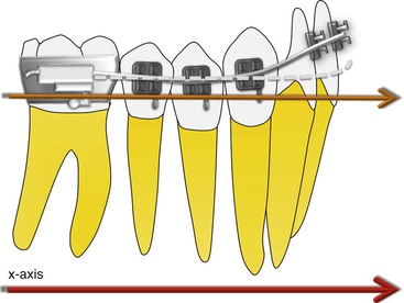
Figure 4-1 The amount of intrusion of the incisors can be measured using two different methods. Method 1: The reference frame chosen is the posterior teeth, indicated by the orange axis. During intrusion of the incisor the posterior teeth will not remain stationary and will show some movement (i.e., the reference frame itself will move). Therefore any measurement made on the incisor will provide information relative to the posterior teeth, not the “absolute” movement of incisors. Method 2: A reference frame outside the system is chosen, indicated by the red axis. This reference frame is not included in the system and is therefore free of any type of movement.
Establishing a Frame of Reference
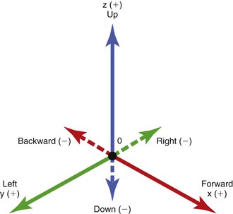
The simplest and the most intuitive way of identifying direction of tooth movement is to create planes or axes of measurement according to the relationship of teeth to the ground. The axes or planes of measurement are then identified as spatial. Any plane or axis that is parallel to the ground is identified as a horizontal plane or axis. Any plane or axis that is perpendicular to the ground is identified as a vertical plane or axis. The two axes that are perpendicular to each other but parallel to the ground are designated as the x and y axes. The x axis is parallel to the ground and directed forward and backward relative to the object of measurement. Forward is designated as positive (+) and backward is designated as negative (–). The y axis is directed left and right relative to the object of measurement. The left direction is designated as positive and the right direction is designated as negative. The third axis, which is perpendicular to the other two, is vertical and is designated as the z axis. The upward direction is positive and the downward direction is negative. These three axes (x, y, and z) are used to describe the location of a tooth or a system under study and the direction of movement. The spatial axes do not change with the body or object changing orientations in space. They are fixed relative to the ground and the observer (Fig. 4-2).
Force
The role of force in everyday life is a familiar one. Indeed it seems almost superfluous to try to define such a self-evident concept as force. To put it in a simple way, force can be thought of as a measure of the push or pull on an object. However, from our perspective, such a simplistic definition is not good enough. The study of the mechanics of tooth movement demands a precise definition of force. So, what is force? A force is something that causes or tends to cause a change in motion or shape of an object or body. In other words, force causes an object to accelerate or decelerate. It is measured in Newtons (N) but in orthodontics force is nearly always measured in grams (g).
Force has four unique properties, as shown in the graphic representation of a force acting at an angle to a central incisor in Figure 4-3:
• Magnitude: The “amount” of force being applied (e.g., 1 N, 2 N, 5N).
• Direction: The way the force is being applied or its orientation to the object (e.g., forward, upward, backward).
• Point of application: Where the force is applied on the body or system receiving it (e.g., in the center, at the bottom, at the top).
• Line of action of force: This is a straight line constructed in the same plane and in the direction of force extending through the point of application.
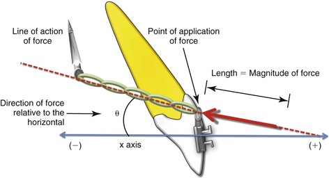
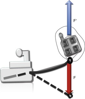
Figure 4-3 The four properties of an external force applied to a tooth illustrated by an elastic chain applying a retraction (distalizing) force on a maxillary incisor to a mini-implant.
Force Diagrams and Vectors
Physical properties (such as distance, weight, temperature, and force) are treated mathematically as either scalars or vectors. Scalars, including temperature and weight, do not have a direction and are completely described by their magnitude. Vectors, on the other hand, have both magnitude and direction. Forces may be represented by vectors.
To move a tooth predictably, a force must be applied with an optimal magnitude, in the desired direction, and at the correct point on the tooth. Changing any of the four properties, discussed above, will affect the quality of tooth displacement. A force may be represented on paper by an arrow. Each of its four properties may be represented by the arrow whose length is drawn to a scale selected to represent the magnitude of the force—for example, 1-cm = 1 N or 2-cm = 2 N (Fig. 4-4). The arrow is drawn to point in the direction in which the force is applied and the tail of the arrow is placed at the point of force application. The line of action of the force may be imagined as continuing indefinitely in both directions (head and tail ends), although the actual arrow, if drawn to scale, must remain a given length. A graphic representation of a force of 1 N acting at an angle of 30 degrees to a central incisor is shown in Figure 4-3.
Principle of Transmissibility
The principle of transmissibility is very important in vector mechanics, especially in understanding equilibrium and equivalent force systems, as we will see later. It implies that a force acting on a rigid body results in the same behavior regardless of the point of application of the force vector as long as the force is applied along the same line of action.
The Effect of Two or More Forces on a System: Vector Addition
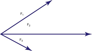
Teeth are often acted upon by more than one force. The net effect or the resultant of multiple forces acting on a system, in this case teeth, can be determined by combining all of the force vectors. This process of combining all of the forces may be found by a geometric rule called vector addition, or vector composition. We place the vectors head to tail, maintaining their magnitudes and directions, and the resultant is the vector drawn from the tail of the first vector to the head of the final vector. Vector addition can be accomplished graphically by drawing diagrams to scale and measuring or by using trigonometry.
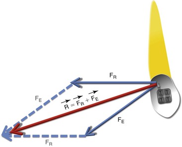
Figure 4-5 shows how the two forces are visualized as two sides of a parallelogram and how the opposite sides are then drawn to form the whole parallelogram. The resultant force, R, is represented by the diagonal that is drawn from the corner of the parallelogram formed by the tails of the two force vectors.
The Directional Effects of Force: Vector Resolution
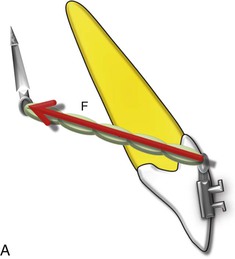
Often an occasion arises in which the observed movement of a system or a single force acting on a system will be analyzed in terms of identifying its component directions. In such cases the single vector quantity given is divided into two components: a horizontal component and a vertical component. The directions of these components are relative to some reference frame, such as the occlusal plane or the Frankfort horizontal (FH) plane, or to some axis in the system itself. The horizontal and vertical components are usually perpendicular to each other. Such a process may be thought of as the reverse of the process of vector composition. The operation is called vector resolution and is the method used to determine two component vectors that form the one vector given initially.
For example, a mini-implant as shown in Figure 4-6, A is being used for retraction of anterior teeth. It may be useful to resolve this force into the components that are parallel and perpendicular to the occlusal plane, in order to determine the magnitude of force in each of these directions. Resolution consists of three steps (see Fig. 4-6, B and C): (1) draw the vector given initially to a selected scale, (2) from the tail of the vector, draw lines representing the desired directions of the two perpendicular components, and (3) from the head of the vector, draw lines parallel to each of the two direction lines so that a rectangle is formed. Note that the new parallel lines constructed have the same magnitude and direction as the corresponding lines on the opposite side of the rectangle.
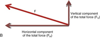
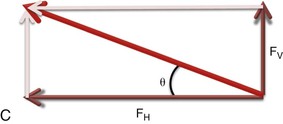
It is important to note that if it is desirable to estimate the magnitude of the components, simple trigonometric rules can be invoked to do so. In particular, the sine and cosine are very useful in finding the horizontal and vertical components of the force vector. In this case if, for example, the horizontal component of magnitude (FH) makes an angle (θ) with the force (F), we can derive the components using the definitions of sine and cosine:


With a little practice, it is easy to get the component directly as a product, skipping the step involving the proportion. Think of sin θ and cos θ as fractions that are used to calculate the sides of a right triangle when the hypotenuse is known. The side is always less than the hypotenuse and the sine and cosine are always less than 1. To get the side opposite the angle, simply multiply the hypotenuse by the sine of the angle. To get the side adjacent to the angle, multiply the hypotenuse by the cosine of the angle.
Center of Resistance, Center of Gravity, and Center of Mass
Once a force is applied to a body, its nature of motion is regulated to a large extent by its center of mass. The center of mass of a body may be thought of as that point at which all of the body's mass seems to be concentrated (i.e., if a force is applied through this point, the system or body will move in a straight line). On similar lines recall that the earth exerts a force on each segment of a system in direct proportion to each segment's mass. The total effect of the force of gravity on a whole body, or system, is as if the force of gravity were concentrated at a single point called the center of gravity. Again, if a force is applied through this point, it will cause the body to move in a straight line without any rotation. The difference between the center of mass and the center of gravity is that the system in question in the latter is a “restrained system” (restrained by the force of gravity).
Teeth are part of a restrained system. Besides gravity they are more dominantly restrained by periodontal structures that are not uniform (involving the root but not the crown) around the tooth. Therefore the center of mass or the center of gravity will not yield a straight line motion if a force is applied through it because the surrounding structures and their composition alter this point. A new point analogous to the center of gravity is required to yield a straight line motion; this is called the center of resistance (CRES) of the tooth (Fig. 4-7).
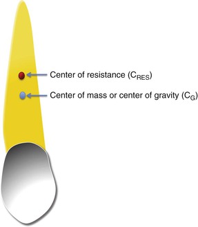
Figure 4-7 The CRES of a tooth is usually located slightly apical to the CG. The periodontal structures surrounding the tooth root cause this apical migration of the CRES.
The center of resistance can also be defined by its relationship to the force: a force for which the line of action passes through the center of resistance producing a movement of pure translation. It must be noted that, for a given tooth, this movement may be mesiodistal or vestibulolingual, intrusive or extrusive. The position of the center of resistance is directly dependent on what may be called the “clinical root” of the tooth. This concept takes into account the root volume, including the periodontal bone (i.e., the distance between the alveolar crest and the apex), incrementing this value with the thickness (i.e., the surface) of the root.1
Thus the position of the center of resistance is also a function of the nature of the periodontal structures and the density of the alveolar bone and the elasticity of the desmodontal structures, which are strongly related to the patient's age.2–4 These considerations implore us to speak of the “center of resistance associated with the tooth” rather than “the center of resistance of the tooth.”
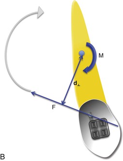
Moment (Torque)
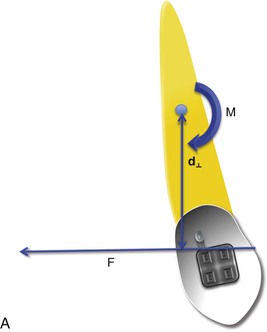
When an external force acts on a body at its center of gravity (CG) it causes that body to move in a linear path. This type of force, with its line of action through the CG or CRES, is called a centric force. On similar lines eccentric forces (off-center forces) act away from the CRES of a body. What kind of effect will these forces have? Besides causing the body to move in a linear path, the eccentric force will have a turning effect on the body called torque; in other words, the force will also impart a “moment” on the body. The off-axis distance of the force's line of action is called the force arm (or sometimes the moment arm, lever arm, or torque arm). The greater this distance, the greater the torque produced by the force. The specifications of the force arm are critical. The force arm is the shortest distance from the axis of rotation to the line of action of force. Invariably the shortest distance is always the length of the line that is perpendicular (90 degrees) to the force's line of action (d⊥). The symbol ⊥ designates perpendicular. Force arm is critical in determining the amount of moment acting on the system.
The amount of moment (M) acting to rotate a system is found by multiplying the magnitude of the applied force (F) by the force arm distance (d⊥):
Therefore the unit for moment used in orthodontics is Newton millimeter (Nmm). As mentioned, often for measuring force Newton is replaced with gram (g); therefore the unit for moment becomes gram-millimeter (g-mm). The larger the force and/or the longer the force arm, the larger the moment. Due to this intrinsic relationship of the moment and the associated force, it is also known as “moment of the force” (MF).
If forces are indicated by straight arrows, moments can be symbolized by curved arrows. With two-dimensional diagrams, clockwise moments will be arbitrarily defined as positive and counterclockwise moments as negative, or vice versa. Values can then be added together to determine the net moment on a tooth relative to a particular point, such as the center of resistance. Point of application and line of action are not needed, nor are graphic methods of addition. The direction of a moment can be determined by continuing the line of action of the force around the center of resistance, as shown in Figure 4-8, B.
Couple (A Type of Moment)
A couple is a form of moment. It is created by a pair of forces that have equal magnitudes but opposite sense (direction) to one another with noncoincidental line of action (parallel forces). Because the forces have the same magnitude but are oppositely directed, the net potential of this special force system to translate the body upon which it acts is nil and there is only rotation.
A typical couple is shown in Figure 4-9. Although the couple's vector representation is shown midway between the two forces, the vector has no particular line-of-action location and may be drawn through any point of the plane of the couple. Therefore a couple is also known as a “free vector.” This freedom associated with the couple vector has far-reaching implications in clinical orthodontics and to certain force analysis procedures. As an example, no matter where a bracket is placed on a tooth, a couple applied at that bracket can only cause the tooth to feel a tendency to rotate around its center of resistance. This is also referred to as the moment of the couple (MC).
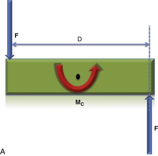
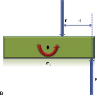
Figure 4-9 A, The moment created by a couple is always around the CRES or CG (MC = F × D). B, No matter where the pair of forces is applied, the couple created will always act around the CRES or CG. As the distance between the two forces decreases (d < D), the overall magnitude of the couple decreases (mc < MC).
The magnitude of the couple (MC) is dependent on both force magnitude and distance between the two forces. The moment created by a couple is actually the sum of the moments created by each of the two forces. If the two forces of the couple act on opposite sides of the center of resistance, their effect to create a moment is additive. If they act on the same side of the center of resistance, they are subtractive (Fig. 4-10). Either way, no net force is felt by the tooth, only a tendency to undergo pure rotation.
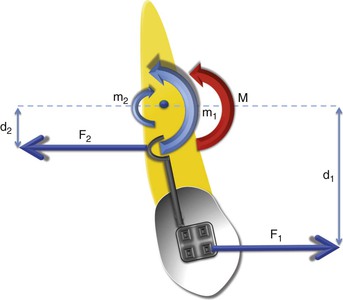
Figure 4-10 A couple created by two equal and opposite forces acting on a tooth. The total moment (M) is the vector addition of the two moments (m1, m2) generated by the two forces (F1, F2). Here, m1 = F1 × d1, m2 = F2 × d2. Because the two moments are in the opposite direction, one of the moments will be assigned a negative sign and the other a positive sign. The net moment (M) will be obtained by adding the two: M = m1 + (–m2).
Equilibrium and Newton's Laws
No object is ever acted on by a single force. The essential factor causing acceleration is the net force, which is the resultant force or unbalanced force. For instance, if two equal and opposite forces act on a body, there is no net force to cause acceleration and the body's velocity remains constant. This condition of constant velocity or no velocity (rest) is called equilibrium. For example, the teeth in the mouth are at rest; they are not moving at all or rather they are at equilibrium (i.e., the sum of all forces acting on the teeth is zero). This brings us to a very important law in mechanics: Newton's First Law of Motion, often called the law of inertia. According to this law, a body or object remains at rest or, if in motion, remains in uniform motion with constant speed, unless it is acted on by a net unbalanced external force. This First Law is, of course, merely a statement of the quantitative definition of force we have already given and recognizes an essential property of matter. In practical use the First Law fully justifies the inherent rest position of a tooth or the inertia of the tooth, which is “rest.”
To extend the laws of motion, we naturally seek a law describing what happens when a net force is applied to a body. And this brings us to Newton's Second Law of Motion, which states that if an object is subjected to an unbalanced system of forces, the object will be accelerated in the direction of the net force exerted. In its simplified version this can be written as:
We can immediately see that the First Law is simply a special case of the Second Law (i.e., if the net force acting on a body is zero, then the acceleration is automatically zero).
Newton's Third Law of Motion (Action and Reaction) is directly related to what is done in day-to-day orthodontics. According to this law, forces always occur in pairs. Any time a wire puts a force on a bracket, the bracket puts the same force on the wire (Fig. 4-11). When swimming, a person interacts with the water, pushing the water backward while the water simultaneously pushes the person forward; both the person and the water push against each other. Facts such as these can be summarized as follows: Whenever one body exerts a force on a second body, the second body exerts a force on the first body; these forces are equal in magnitude and oppositely directed. Newton called these paired forces action and reaction. It is essential to understand that the two forces act on different bodies and hence cannot add up to zero.
Concept of Equilibrium
The word equilibrium has several different meanings but in statics it is basically defined as a state of rest; in particular, it means that an object or system is not experiencing any acceleration. Therefore statics is that branch of physics that deals with the mechanics of nonaccelerating objects or, for our convenience and understanding, “nonmoving” objects. Such a system is said to be in equilibrium. To achieve equilibrium, we must see to it that no unbalanced force is applied to the body in question or, in other words, that any force acting on a system is balanced by contrary forces. Therefore the sum of all forces should be zero (ΣF = 0). (According to Newton's Second Law of Motion, if a system is not accelerating, then a = 0, so ΣF = ma or ΣF = m(0) or ΣF = 0. That is, there is no net force acting on the system.)
A vector can be zero only if each of its perpendicular components is zero; thus the single vector equation ΣF = 0 is equivalent to three component equations: ΣFx = 0, ΣFy = 0, and ΣFz = 0 (x, y, and z are the three spatial axes discussed previously). On similar lines the net moment in all three planes also should be equal to zero (i.e., ΣMx = 0, ΣMy = 0, and ΣMz = 0).
Equilibrium in Orthodontics (The Quasi-Static System)
Equilibrium applies only to static systems (nonaccelerating systems). However, in orthodontics we move teeth. They move, stop, tip, and upright (i.e., they are not static systems). So how can teeth be governed by the laws of statics? To answer this question, we need to redefine the state of the teeth subjected to orthodontic forces by introducing the concept of quasi-static systems (or quasi-static thermodynamic processes). This concept can be defined as a system or process that goes through a sequence of states that are infinitesimally close to equilibrium (i.e., the process happens very slowly and goes through a sequence of states that are close to equilibrium at any time). When orthodontic appliances are activated and inserted, the tooth displacement that occurs is very small and takes place over a relatively long period of time. At any point in time, if you look in the patient's mouth you do not see any movement; however, after waiting for a sufficient period the movement can be appreciated. Therefore at any instant a force analysis may be carried out by invoking the laws of equilibrium without erring appreciably. In other words, the inertia of any appliance element or a tooth is negligibly smaller and may be neglected. For this reason, the physical laws of statics are considered adequate to describe the instantaneous force systems produced by orthodontic appliances. However, these laws cannot be used to describe how the force systems will change as the teeth move and an appliance deactivates and alters its configuration.
The solutions to problems in statics involving forces and moments call for ingenuity and common sense. There are no simple rules of procedure. The most common source of error is failure to identify the object whose equilibrium is being considered. You must learn to consider all forces acting on the body. Of course, Newton's Second and Third Laws of Motion are of great help in this regard. By using the Third Law, it is easy to figure out that if an appliance is exerting a force on a tooth, the tooth is exerting the same force on the appliance (see Fig. 4-11), and the same principle applies to all other teeth to which the appliance is connected. Because the appliance is not moving (static), the sum of all forces and moments produced by the appliance should be zero.
Principle of Equivalent Force Systems
The principle of equivalent force systems is an elegant way of redefining the forces and moments acting on a body. It helps to visualize not only the translatory movement of a tooth but also the rotation, tip, and torque experienced. An equivalent force system is a system of forces and/or moments that can be replaced with a different set of forces and/or moments and still achieve the same basic translational and rotational behavior. To understand the practical implication of this principle, let us discuss relocating a force system on a molar.
Application of Equivalent Force Systems: Moving the Force System to a Different Location
Figure 4-12 shows a force acting on the tooth at point A (FA). Now suppose that you want to compute the effects of this force system at a different location, such as point B, which in this case is the CRES of the molar (remember that the CRES of the molar has been chosen arbitrarily; point B can be any other point on the molar). To determine the required translational effect, introduce two equal but opposite forces (+FA′ and –FA′) at point B. We can easily do this because such an introduction of forces will not affect the system in any way, as these forces are equal and opposite and therefore the resultant of these newly added forces is FA′ + (–FA′) = 0, or zero net translational effect. Make sure that the magnitude of these new forces is equal to FA acting at point A. Now, by applying the law of vector addition the original force FA plus the new negative force –FA′ will cancel each other out. With this in mind, you can see that the only force that now remains on the molar is the newly relocated force FA′, which is now acting at point B. Congratulations! You have relocated the force.
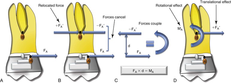
Figure 4-12 Creating equivalent force systems. The net effect of the force system depicted in A and D is the same. B and C show how to transform A to B.
Now that you have relocated the force, examine the two other forces on the molar: FA acting at point A and –FA′ acting at point B. These two forces are parallel, acting in opposite directions and separated by a distance (d). This setup is the very definition of a moment (couple), previously discussed. Remember that moments and couples cause rotation of a body; therefore the added rotational effect of this couple is what you must include when you move a force. Also, a couple is a free vector; therefore it applies the same rotational behavior regardless of where on the body it is acting. As a result, you can freely move the moment of the couple to point B on the molar as long as the magnitude and sense of the moment vector remain unchanged. The magnitude of this moment can be calculated by multiplying the force FA or –FA′ by d (MA = FA × d). The point of application of a moment or couple doesn't matter when creating an equivalent force system. If you want to move a moment, just move it.
In summary, to relocate a force system you simply need to take the original force and apply it to the new location, plus compute the newly applied moment (which is the product of the force and the distance between the two points) and apply that at the new location maintaining its sense and direction.
There are two simple rules that allow the calculation of equivalent force systems. Two force systems are equivalent if (1) the sums of the forces in all three planes of space (x, y, and z) are equal and (2) the sums of moments about any point are identical.
Center of Rotation
Center of rotation is a fixed point around which a two-dimensional figure appears to be rotated as determined from its initial and final positions. (Note that a two-dimensional figure always rotates around a point while a three-dimensional figure rotates around an axis; that is, a two-dimensional object has a center of rotation while a three-dimensional object has an axis of rotation.) In other words, in rotation the only point that does not move is called the center of rotation (CROT) (Fig. 4-13). The rest of the plane rotates around this one fixed point.
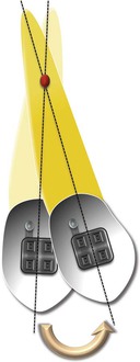
Figure 4-13 Center of rotation (red dot) of a tooth. Note that the center of rotation is the only point that has remained stationary.
Although a single center of rotation can be constructed for any starting and ending positions of a tooth, it does not follow that the single point actually acted as the center of rotation for the entire movement. The tooth might have arrived at its final position by following an irregular path, tipping first one way and then another. As a tooth moves, the forces on it continuously undergo slight changes, so that a changing center of rotation is the rule rather than the exception. In determining the relationship between a force system and the center of rotation of the resulting movement, all that can really be determined is an “instantaneous” center of rotation.5
Estimating the Center of Rotation
The CROT can be estimated easily as shown in Figure 4-14. Take any two points on the tooth and connect the before and after positions of each point with a line. The intersection of the perpendicular bisectors of these lines is the center of rotation.6

Figure 4-14 A and A′ represent the cusp tip before and after movement. A line has been drawn connecting these points. At the midpoint of this line a perpendicular has been constructed. The point at which this perpendicular intersects any other perpendicular constructed in a similar manner (here, the apex has been selected as the other point) is the center of rotation (red dot).
Types of Tooth Movement (Fig. 4-15)
As discussed in the preceding section, the center of rotation is the key to defining the nature of tooth movement. Controlling the CROT automatically gives precise control over the type (extent) of tooth movement. When a single force is applied on a tooth, the tooth will move in the direction of the force applied. Additionally, depending on the distance of the force from the CRES the tooth will experience a moment (MF) around the CRES. This combination of a force and a moment will cause the tooth to rotate as it moves, placing its CROT slightly apical to the CRES.1,5,7 This type of tooth movement is called simple tipping or uncontrolled tipping. It is easy to visualize here that the crown and the root will move in opposite directions. Tipping can happen in many different ways depending on where the CROT is along the tooth. However, for ease of classification they can be categorized into two groups:
• Controlled tipping: During such movement the CROT is located at the root apex. The tooth moves similar to the pendulum on a clock, with its apex fixed at a particular point and the crown moving from one side to the other.
• Root movement: Here, the CROT is located at the crown tip while the root is free to move in the direction of the force. Traditionally, in the orthodontic literature, this is not characterized as a tipping movement but mechanically the movement is similar to controlled tipping.
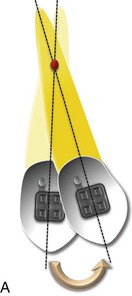
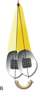
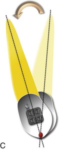
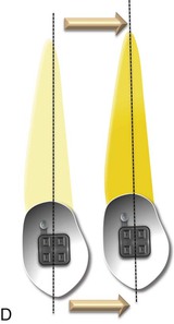
Figure 4-15 Types of tooth movement. A, Uncontrolled tipping. B, Controlled tipping. C, Root movement (torquing). D, Translation or bodily movement. The CROT in every case is depicted by a red dot. Note that during translation (D) the CROT is at infinity or, in other words, does not exist.
Almost the entire universe of tooth movement consists of tipping the crown, the root (rare), or a combination (most common). However, there is one tooth movement that is extremely rare and very difficult to achieve in its strictest sense: translation, sometimes known as bodily movement. Here, both the crown and the root move in equal amounts and in the same direction with no rotation. In this case the CROT is nonexistent or, in mathematical terms, approaches infinity.
Moment-to-Force (M/F) Ratios
Tipping (uncontrolled) is the most common tooth movement in everyday orthodontics but not always the preferred one. To modify this pattern of tooth movement and create a new one, the force system acting on the tooth needs to be altered. There are primarily two ways to accomplish this based on the mechanics involved:
1. Altering the point of force application (Fig. 4-16): A simple way of accomplishing this is to apply a force closer to the CRES of the tooth. A rigid attachment, often called a power arm, can be attached to the bracket on the crown of the tooth. Then the force can be applied to this power arm. In this way the line of force can be moved to a different location, thereby altering its distance from the CRES. This also causes a change in the moment of the force. For example, if the power arm can be made long and rigid to extend to the CRES of the tooth, the moment arm (MF) can be eliminated entirely, as the applied force will now pass through the CRES. This method works beautifully when altering the tipping movement of the crown; however, for movements requiring higher levels of control, such as translation and root movement, this method poses certain problems. The “long” arms can be a source of irritation to the patient, by extending into the vestibule and/or impinging on the gingiva and cheeks. Additionally, the arms are sometimes not rigid enough and can undergo some degree of flexion under the applied force. (A clinical case showing translation with power arms has been described in Chapter 6.)
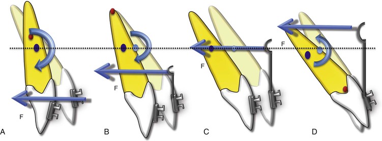
Figure 4-16 The application of a power arm to create different types of tooth movement. Note that the force has been kept constant through A to D. A, Uncontrolled tipping, no power arm. B, Controlled tipping produced by a power arm below the CRES of the tooth. C, Translation, as the force is now being applied through the CRES made possible by increasing the length of the power arm. D, Root movement with minimal crown movement; here, the power arm extends beyond the CRES. (The red dot is the CROT and the blue dot is the CRES.) Note how the MF increases or decreases with an increase or decrease in the distance of force application from the CRES.
2. Altering the moment-to-force ratio (Fig. 4-17): An alternative method to alter the tooth movement is to play with the rotational component of the applied force (i.e., the MF). This is done by adding a counterbalancing moment (i.e., a moment in the opposite direction to that of the MF) to the system. This new moment can be created in two ways. The first approach is the traditional way of applying a force (this would be a different force than the one generating the MF). However, with a bracket fixed on the tooth it is usually difficult to apply a force at some other point. Therefore this approach is usually not practical or efficient. The second approach involves creating a couple in the bracket. A rectangular archwire fitting into a rectangular bracket slot on the tooth is the most widely used method. This new moment (MC) together with the applied force determines the nature of tooth movement. This combination is popularly known as the moment-to-force (MC/F) ratio. By varying this M/F ratio the quality of tooth movement can be changed among tipping, translation, and root movement (i.e., different centers of rotation along the long axis of the tooth are created by changing the magnitude of the couple and the applied force). In terms of the direction, the moment of the couple (MC) is almost always going to be in the direction opposite the moment of the force (MF) about the CRES.
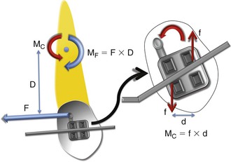
Figure 4-17 A schematic diagram depicting the generation of a moment due to a couple (MC). It is the ratio of the MC to the force applied (F) that determines the nature of tooth movement (M/F ratio). The higher the ratio, the greater will be the control over the tooth movement.
Note that in orthodontics moments are measured in gram-millimeters and forces are measured in grams, so that a ratio of the two has units of millimeters. This ratio is also indicative of the distance away from the bracket at which a single force will produce the same effect (i.e., through a power arm, as discussed above).
Orthodontic Force Systems: Applying the Laws of Mechanics
From our discussion in the previous sections it is clear that orthodontic tooth movement follows certain principles of classical or Newtonian mechanics that need to be understood to carry out a particular type of tooth movement. Once you have mastered these fundamental laws, the next task it to put them into action. It is important to remember that the physical laws or the brackets on the patient's teeth by themselves will not move teeth. They must work in conjunction with a set of wires to generate the required forces and moments for moving teeth. Placing bends in a wire at strategic locations between two or more brackets is one way of using these laws to move teeth in a predictable fashion. This is often done during the finishing stages of treatment. The other method is to offset the brackets in relation to each other to create the same forces and moments. This is what happens during the initial stages of treatment when teeth are not aligned and a straight wire is put in the brackets to align them. Let's discuss these situations in detail.
Bends placed on a wire between two attachments or brackets or a straight wire linking maligned brackets or attachments can essentially create two kinds of force systems depending on how the wire is engaged in the brackets:
One-Couple Force Systems
The orthodontic appliances capable of producing the most well-defined and dramatic tooth movements are often those that are the most simple biomechanically. These force systems are established between two attachments when a couple is created at one end of an attachment and a single force is created at the other. This usually involves a wire with a bend inserted in a bracket or tube while at the other end, instead of placing the wire in a bracket or tube slot, it is just tied to the attachment so that only one point of contact is created. This system therefore is also known as a one-bracket force system (Fig. 4-18). Due to the simple configuration of the action and reaction forces this system generates a statically determinate force system (i.e., all forces and moments created by such a system can be readily discerned, measured, and evaluated with remarkable precision). There are a number of clinical situations in which we make use of such a force system. Some of them have been discussed in Chapter 8.
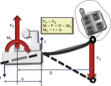
Figure 4-18 Schematic diagram illustrating a one-couple force system. The moment (M) generated by the system is the product of the force and the distance (D) separating the two forces, which causes the entire system to rotate. As with every rigid body system, this setup should be in equilibrium; in other words, the sum of all forces and moments should be zero. Therefore the two forces (FP and FA) should be equal. Also, the moment due to the couple (MC) in the tube should be equal to the moment of the system (M). The MC is generated by the wire contacting the edges of the tube generating the forces (f) shown in blue.
A cantilever spring design is the essential component of all appliances using the one-couple force system. Figure 4-18 illustrates the mechanics involved when using a cantilever spring for canine extrusion. The mechanics shown apply to all one-couple force systems. Note that the spring is simply tied to an attachment or bracket and not inserted in the bracket slot so that there is only a single point of contact between the wire and the attachment, creating a single force with no couple as opposed to the two-point contact in the other attachment (tube). Such a quasi-static system (neither the wire nor the attachments are moving at a particular instant of time) will abide with the laws of equilibrium, as this is a ”rigid system.” Therefore the moment at the tube (MC) should be opposed by another moment (M) in the opposite direction but one of equal magnitude. This M is produced by the equal and opposite forces (FA and FP) at the attachments. The forces again follow the law of equilibrium. (Note: The equal and opposite forces seen at the two attachments are not a consequence of Newton's Third Law of Motion.)
At the clinical level, the most consistent way to derive the force system produced by any orthodontic appliance is to remove the activated wire from its attachments and lay it passively over the attachment sites. The angle formed by the wire and the brackets will show the direction of the couple produced at the site of engagement, where the angle between the wire and bracket is largest.8–10
Two-Couple Force Systems
Two-couple force systems are established between two attachments when a wire is inserted in the bracket slots of two brackets or tubes. As the name suggests, these force systems involve forces and couples at both attachments when a straight wire is placed in a pair of nonaligned brackets or when a bend is placed between two aligned brackets. Therefore this force system is also known as a two-bracket force system. The dynamics of this two-bracket unit are fundamental in understanding the mechanical principles guiding the movement of teeth with sliding mechanics.
When compared to the force system described in the previous section (i.e., one-couple force systems) this constitutes a statically indeterminate force system (i.e., it is too complex to “precisely” determine all of the forces and moments involved at both attachments at a particular time). Inserting the wire into one attachment and using a force gauge to measure the force required to deflect the wire to the other bracket will not necessarily give an accurate assessment of the force produced by the wire. In this system, when the wire is placed over the slots of the two brackets where it will be inserted, the angle of entry of the wire at each bracket slot does show which bracket has the larger angle of entry and therefore the larger moment. This is important because, irrespective of the direction of the moment at the second bracket, the larger moment will dictate the direction of the associated net equilibrium of forces acting at each bracket.
As mentioned previously, the two-bracket force system can be described by two different approaches and has been described in detail in the orthodontic literature11–13: straight wire placed in angulated brackets (super-position method) and angulated (bent) wires in aligned brackets (subtraction method).
Straight Wire Placed in Angulated Brackets
This approach allows the orthodontist to use a straight wire in malaligned brackets. This triggers the activation of the force system. The force system can be accentuated by adding the proper bends whose force systems are summated to the straight-wire force system. This is known as the “superposition” method and is often used during the initial and leveling and aligning phases of orthodontic treatment or sometimes during finishing when bracket positions are changed for root correction.
The first step in understanding this method is to accurately define the system. Figure 4-19 shows the setup of such a system. The interbracket axis (D) connects the centers of the two attachments. This can also be called the “interbracket distance” or the x-x′ axis, as described in the beginning of this chapter. Both brackets make certain angles with this horizontal (x-x′) axis. The two attachment–wire segment can be fully defined if one knows θA, θB, and D. There are an infinite number of ways in which the brackets can be arranged relative to each other, in terms of both angulation and the distance. To make things easy, such a setup can be studies in six distinct geometries. Each geometry or arrangement of the brackets can be defined by the ratio of the bracket angulations relative to the x-x′ axis. Every geometry has its own unique set of force systems and is represented by a “class.” Let us examine each class separately.
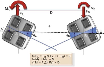
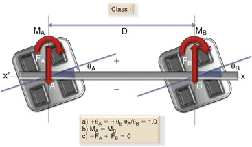
Figure 4-19 Wire-attachment geometry is defined by the interbracket distance (D) and the angles of the brackets at positions A and B relative to the horizontal reference frame (x-x′). The purple arrows show how the wire in the bracket creates the couples (MA or MB). Note: The equations mentioned in the box apply to all geometries (Classes I to VI) without exception.
The reader will observe a gradual change in θA while θB is kept constant as we go through the various classes. Since, by convention, θA is always either equal to or smaller than θB, the six classes can be used to describe any two-tooth segments, regardless of the teeth involved. A consistent sign convention is used to describe the angle of the brackets. The sign of the angle is the same sign as the moment required to place the wire into the bracket. At any point, if the axis of the bracket (blue line) goes below the x-x′ line, the sign convention for the angle created (for θA or θB) will be assigned a negative (–). All forces pointing downward and all moments in the counterclockwise direction are negative.
Class I: The two brackets here are angled the same amount and in the same direction with respect to the interbracket axis (D) (i.e., θA = θB and θA/θB = 1.0) (Fig. 4-20). The two moments are equal; the ratio MA/MB = 1. Although the magnitude of the moments may vary, depending on the amount of activation and the interbracket distance, the ratio of MA to MB always remains +1 in Class I. In addition to the moment, two vertical forces are also produced: a negative force at position A and a positive force at position B. Force A equals force B as dictated by the laws of equilibrium.
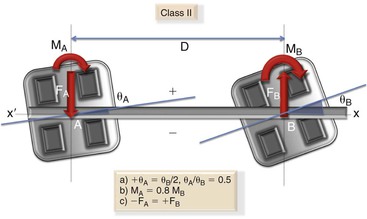
Class II: The Class II geometry is characterized by θA having a magnitude of one-half of θB (Fig. 4-21). Two positive moments are created at the wire at positions A and B. The magnitude of the moment at A is 0.8 times the moment at B. A positive force is found at A and a negative force is found at B.
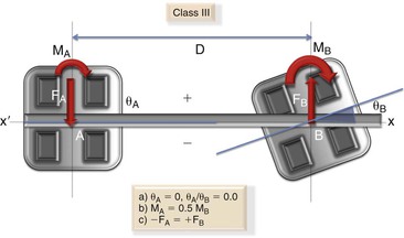
Class III: In Class III geometries the interbracket axis cuts across the two brackets; in other words, the angle made by bracket A with respect to the x-x′ axis or the wire is 0 degrees (Fig. 4-22). So, θA/θB is 0; thus a wire placed in the canine bracket (A) would cross the premolar bracket (B) at the center of the slot. Two positive moments are created at the wire at positions A and B. The magnitude of the moment at A is 0.5 times the moment at B. A positive force is found at A and a negative force is found at B.
Class IV: Here the bracket A is angled one-half of bracket B but in the opposite direction in relation to the x-x′ axis (i.e., θA = –0.5θB) (Fig. 4-23). The ratio between θA/θB is –0.5. In this geometry a positive moment is found at position B but no moment whatsoever is found at position A. Only a single force operates at position A, with an equal and opposite force at position B. Since no moment is acting in position A, the ratio of MA/MB is equal to 0. It is interesting to note that in this geometry the system almost behaves like a one-couple force system.
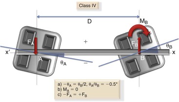
Figure 4-23 Class IV geometry. (*Negative sign indicates that bracket A is angled in the opposite direction to that of bracket B.) Note: There is no moment at bracket A.
Class V: Bracket A is angled three-fourths of bracket B but in the opposite direction in relation to the interbracket axis (x-x′ axis) (i.e., θA = –0.75θB) (Fig. 4-24). The ratio between θA/θB is –0.75. In this example the moment at A is negative and its magnitude is two-fifths of the positive moment at B. The ratio of MA/MB is –0.4. Equal and opposite vertical forces act at positions A and B.

Class VI: In this class the bracket A is angled the same amount as bracket B but in the opposite direction so that the ratio of the angle (θA/θB) is –1.0 (Fig. 4-25). The force system acting on the wire is composed of equal and opposite moments (negative at A and positive at B) (i.e., MA/MB is –1.0). No vertical forces are present.
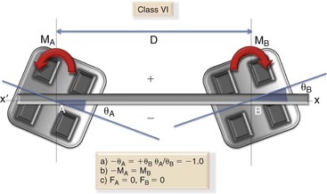
Figure 4-25 Class VI geometry. Note: The moments here are equal in magnitude but in the opposite direction. No vertical forces are created in this geometry.
The six clinical classes actually represent a continuum of possible force systems that can place a wire between two brackets into equilibrium. The important thing here is to know the relative force system rather than the exact magnitude. For example, note how the magnitude of the vertical forces decreases as we go from Class I to II and so on until Class VI, where there are no vertical forces at all. In other words, we can say that as the ratio of θA/θB decreases the force magnitudes decrease. This can be easily figured out from the equations in Figure 4-19:

Of more importance are the relative moments in each class and how the angulation of the brackets can change this. In a dynamic situation (i.e., at the clinical level), as the ratio of θA/θB changes from one class to the next, the force system on the wire, and hence on the teeth, will radically change.
Angulated (Bent) Wires in Aligned Brackets
Bending wires toward the end of orthodontic treatment is a common practice. It helps in giving final touches to a well-treated malocclusion. As with the superposition method, a gamut of possible locations and bend types can be placed. However, to understand the dynamics of such bends, they can be classified into the following categories based on the type of force system each can provide.
In this approach it is important to first contour the wire passively between two brackets and then add the proper “V” or step bends. In other words, this approach first eliminates the force system produced by a straight wire in malaligned brackets and then creates the desired force system by adding bends in the wire. Therefore it is referred to as the subtraction method.
Each of these bends is distinct from the others in terms of the forces and moments produced at both ends.12 It is important to remember that this method produces similar results to those of the superposition method described above and is also classified into various geometries. The various geometries can be categorized as follows:
I. Step bends. Step bends can replicate the Class I and II geometries described in the previous section. They require that two bends be placed on the wire anywhere along the interbracket distance.
Class I: A step in the wire between two brackets produces equal and opposite vertical forces and unidirectional couples whose moments are equal in magnitude (Fig. 4-26). Since the moments are in the same direction and of equal magnitude, the ratio is MA/MB = 1. This ratio defines the relative force system from a step in a wire that is identical to the Class I ratio found with a straight wire with parallel and stepped brackets (see Fig. 4-20). To create a Class I geometry with bends it is important to remember that the wire segments going into the bracket slots should be parallel to each other (shown by blue lines in Fig. 4-26); in other words, the bend angulations should be similar and in the same direction (i.e., θA = θB or θA/θB = 1).
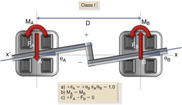
Figure 4-26 Step bends (bend angulations are made in such a way that the two blue lines are parallel to each other), Class I geometry. Note: It does not matter where the step bend is placed between the two brackets; the effect will be similar.
For all practical purposes the shifting of the step mesiodistally does not alter the absolute or relative force system. Furthermore, the ratio MA/MB = 1 is independent of the interbracket distance. It also does not change with smaller or larger step bends.
Class II: The following geometry can be created when bend angulations are not equal to each other (θA ≠ θB) and the wire segments going into the bracket slots if extended with imaginary lines intersect beyond the interbracket span (Fig. 4-27).
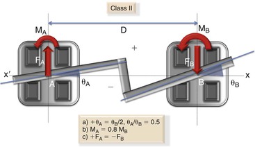
Figure 4-27 Step bends (bend angulations not at 90 degrees), Class II geometry. Note: The bends are placed in such a way that the two blue lines intersect beyond the interbracket distance.
II. Off-centered “V” bends. A “V” bend, as the name indicates, involves the placement of only one bend on the wire along the interbracket distance. Unlike a step bend, a “V” bend placed between two brackets radically alters the force system, depending on the mesiodistal placement of the bend. Therefore, based on the position of the bend, these bends can be arranged into the remaining geometries (Classes III to VI).
Class III: The “V” bend is placed very close to one of the brackets (Fig. 4-28). The bracket near the bend will have the bigger moment, while the moment at the other end will be much lower in magnitude but will have the same sense.
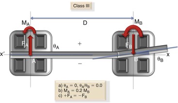
Figure 4-28 Off-centered “V” bend, Class III geometry. Note: The “V” bend is placed very close to one bracket.
Class IV: The “V” bend is placed at one third the interbracket distance. No moment is found at the bracket further away from the bend (Fig. 4-29).
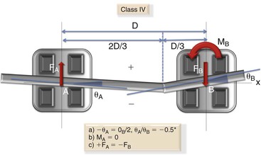
Figure 4-29 Off-centered “V” bend, Class IV geometry. (*Negative sign indicates that bracket A is angled in the opposite direction to bracket B.) Note: The bend is placed at one-third the interbracket distance. There is no moment at bracket A.
Class V: The bend is moved closer to the center of the interbracket distance (Fig. 4-30). From this point onward a moment is seen on the bracket further away from the bend but with an opposite sense.
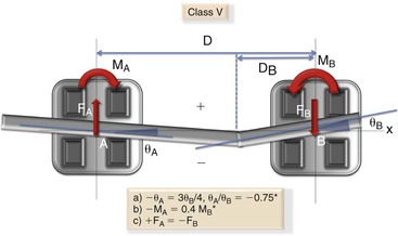
Figure 4-30 Off-centered “V” bend, Class V geometry. (*Negative sign indicates that bracket A is angled in the opposite direction to bracket B and the moment is in the clockwise direction.) Note: Here, the bend is placed in such a way that D/3 < DB < D/2. DB is the distance between the “V” bend and bracket B.
Class VI: When the “V” bend is centered, equal and opposite moments are produced and hence there are no vertical forces (Fig. 4-31).
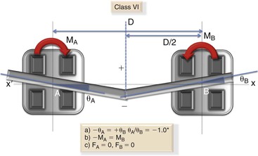
Figure 4-31 Centered “V” bend, Class VI geometry. (*Negative sign indicates that bracket A is angled in the opposite direction to bracket B and the moment is in the clockwise direction.) Note: Here, the bend is placed at half the interbracket distance. There are no vertical forces.
This analysis of the force systems leads to important clinical applications in the use of bends and bracket positioning and angulation in day-to-day orthodontics. It is important to emphasize again the need to appreciate the relative force system not the absolute force. In all of the bend geometries discussed, neither the height of the bend nor the interbracket distance changes the relative force system and obviously the absolute magnitude of the forces and moments will vary. This analysis also forms the basis for analyzing more intricate and complicated force systems that might be generated in an actual clinical situation.
Summary
In this chapter we placed a strong emphasis on the fundamentals of the mechanical principles involved in tooth movement. Later in this book, we will see the clinical applications of these principles. It is our belief that by unraveling the basic mechanics of tooth movement and integrating them with newer advances we can make tooth movement more efficient with minimal side effects. Clinicians who understand the principles of tooth movement will have better control of their treatment mechanics and greater efficiency in tooth movement.
References
1. Burstone CJ, Pryputniewicz RJ. Holographic determination of centers of rotation produced by orthodontic forces. Am J Orthod. 1980;77:396.
2. Davidian EJ. Use of a computer model to study the force distribution on the root of the maxillary central incisor. Am J Orthod. 1971;59:581–588.
3. Hay GE. The equilibrium of a thin compressible membrane. Can J Res. 1939;17:106–121.
4. Yettram AL, Wright KWJ, Houston WJB. Center of rotation of a maxillary central incisor under orthodontic loading. Br J Orthod. 1977;4:23–27.
5. Christiansen RL, Burstone CJ. Centers of rotation within the periodontal space. Am J Orthod. 1969;55:351–369.
6. Smith RJ, Burstone CJ. Mechanics of tooth movement. Am J Orthod. 1984;85(4):294–307.
7. Pryputniewicz RJ, Burstone CJ. The effect of time and force magnitude on orthodontic tooth movement. J Dent Res. 1979;58(8):1754–1764.
8. Mulligan TF. Common sense mechanics in everyday orthodontics. CSM Publishing: Phoenix, AZ; 1998.
9. Isaacson RJ, Lindauer SJ, Rubenstein LK. Activating a 2 × 4 appliance. Angle Orthod. 1993;63:17–24.
10. Demange C. Equilibrium situations in bend force systems. Am J Orthod Dentofacial Orthop. 1990;98:333–339.
11. Koenig HA, Burstone CJ. Force systems from an ideal arch. Am J Orthod. 1974;65:270–289.
12. Burstone CJ, Koenig HA. Force systems from an ideal arch: large deflection considerations. Angle Orthod. 1989;59(1):11–16.
13. Koenig HA, Burstone CJ. Creative wire bending: the force system from step and V bend. Am J Orthod Dentofacial Orthop. 1988;93(1):59–67.