Size Reduction
Size reduction or comminution is the process of reducing substances to small particles, an operation that has to be applied in greater or lesser degree to most drugs for the sake of easy administration and so that they present a large surface to the action of a solvent, thus aiding solution in the case of chemical substances and, in the case of crude drugs, allowing rapid penetration of the liquid used to extract their active constituents.
It is an important preliminary stage in the preparation of compressed tablets, where granular material has to be prepared for the tabletting process. Relatively few drugs can be compressed alone into satisfactory tablets; in general other ingredients have to be added—excipients, disintegrants, diluents and lubricants— and their particle size characteristics have a major influence on the properties of the finished tablets. Comminution is very relevant to the preparation of pharmaceutical dispersions, pastes and fluids, where properties such as consistency, tendency to sediment, appearance and general storage characteristics again depend on the particle size of the solid ingredients.
For sustained release preparations such as testosterone and oestrone, the drug must be within a particular size range if its effects are to be prolonged over a period and if it is not to be excreted too rapidly from the body.
Finally, the reduction of materials to a fine state of subdivision is an essential preliminary to the preparation of pharmaceutical capsules, insufflations (i.e. preparations inhaled directly into the lungs), suppositories, pessaries and ointments, where the requirement is that the solid constituents should be impalpable, i.e. less than about 60μm in diameter.
General Principles
The main object in most size reduction operations is to obtain a product smaller than a certain specified size. Drugs which are to be dispensed in some vehicle for oral or parenteral administration must be in the form of a very fine powder (usually less than 20μm). Where a coarse product is required, e.g. vegetable drugs in a form suitable for extraction, a minimum proportion of fine particles is usually required. The type of size reduction apparatus plays an important part in this respect.
Machinery used for size reduction may be divided into three classes, depending on the size of the product required. Coarse crushers usually accomplish breaking by the application of a continuous pressure, and they yield a product generally greater than 1000μm in diameter.
Intermediate machines employ blow or impact methods and produce powders in which the majority of particles are between about 100 and 1000μm in diameter.
Finally there are the machines which employ grinding or abrasion methods and which are used for preparing the finest powders down to 1μm diameter or below. No sharp dividing line can be drawn between the three classes of machines, but for pharmacists generally the intermediate and fine machines are of greater interest than the crushers.
Mechanism of Size Reduction
The mechanisms involved in size reduction are very complex (
Bickle, 1961) and, as they vary with the nature of the material, no comprehensive treatment is generally available. Theory is of limited use in the choice and operation of machines, and art and experience are still required in order to produce a desired result, since some drugs require individual treatment.
When a solid particle is struck, or is loaded with a force greater than its breaking strength, it generally breaks to form a few relatively large particles and a number of fine particles, but relatively few particles of intermediate size. Increasing the energy of the blow usually increases the number of both large and small particles and decreases the size of the former, but not of the latter. This indicates that the size and number of the large particles is determined by the energy and nature of the breaking process, but that of the smaller particles by the internal structure, nature and presence of fissures in the material concerned.
The energy supplied during comminution is distributed in elastic and plastic deformation of particles, in lattice rearrangements within crystals, and in the increased energy of the material associated with the new surfaces that have been formed. These are produced by fractures which occur along lines of weakness in the material and which open up under pressure or impact, but a very large proportion of the energy supplied is dissipated in the form of heat without achieving any useful result. It has been estimated that in most machines less than 2 per cent of the energy actually supplied is used for producing new surfaces, the rest going in overcoming friction and inertia of the machine parts, in friction between particles and deformation of particles without breaking them.
Many attempts have been made to develop equations for the useful work required to effect a given size reduction (
Dobie, 1952;
Carey & Stairmand, 1952). Rittinger’s law assumes that the energy consumed is proportional to the fresh surface produced. Kick’s law assumes that the energy required for the subdivision of a definite amount of material is the same for the same fractional reduction in size of the individual particles. Thus, if 1.5
kW is required to crush a given weight of a substance from 2–1
cm pieces, the energy required will be the same for crushing 1–0.5
cm or 0.5–0.25
cm pieces. For crushing large particles this appears to give better results than Rittinger’s law, which can be applied more satisfactorily to fine grinding.
A law combining both the above is due to Bond and can be expressed by:
where L1 is the initial diameter of the material in microns L2 is the final diameter of the material in microns, and Ei is the so-called work index, i.e. the amount of energy required to reduce unit mass of the material from a very large size down to a size of 100μm. Work indices for many drugs and excipients are now available.
Size Distribution During Comminution
At all stages during a comminution process there will be a size distribution of particles; no machine can produce a completely uniformly sized product though some, which combine comminution with classification, very nearly do so.
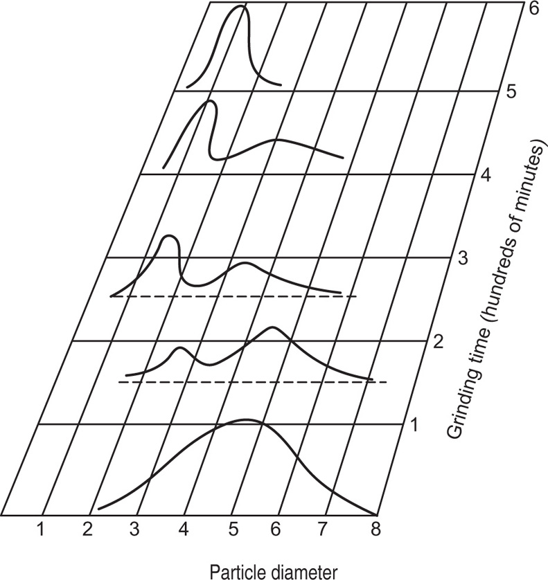
Fig. 19.1 shows schematically the change in particles size distribution which occurs as comminution proceeds (
Herdan et al., 1960).
At the start, when particles of many sizes are present, the distribution curve is rather flat and bell shaped, but in a short while a secondary peak develops and gradually moves to the left. At the same time its height rises indicating increasing production of small sized particles. The height of the secondary peak continues to rise at the expense of the primary, while its width decreases. The final stage is represented by the topmost curve.
By taking samples from a machine after different periods of comminution, and plotting the histograms, it is possible to establish the most satisfactory and economical milling conditions.
Comminution Machinery
Five main types of equipment are in regular use for size reduction of drugs and other pharmaceutical materials and they may be summarized briefly as hand-operated or mechanical pestles and mortars, impact or hammer mills, pin mills, ball mills and vibration mills, and micronizers (
Cremer & Davies, 1957;
Neuman & Axon, 1961).
In addition there are the techniques of spray and freeze drying, crystallization and precipitation, which are being increasingly used for producing drugs in a fine state of division without grinding.
Mortar and Pestle Types
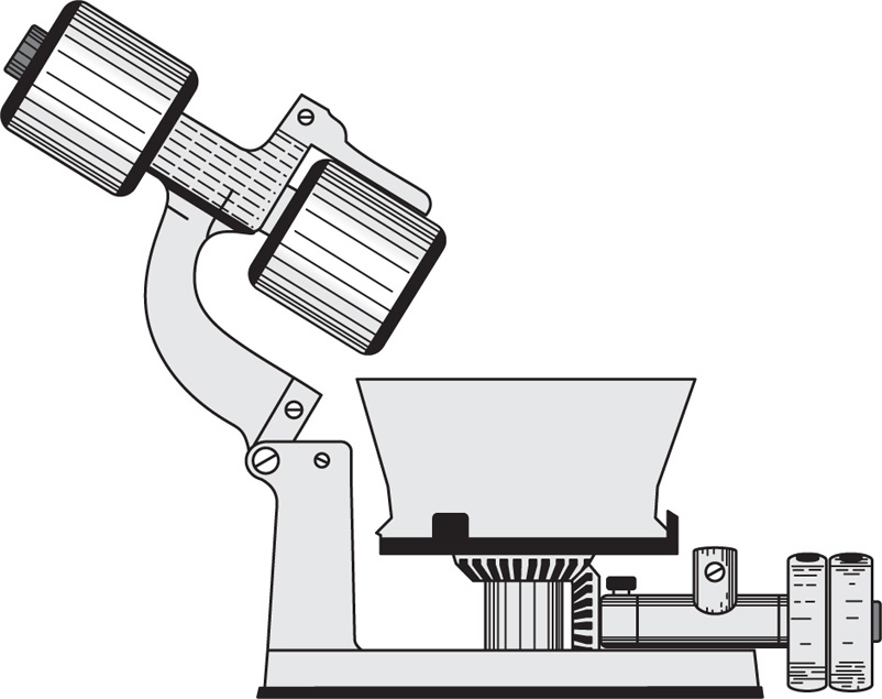
The hand mortar and pestle has for centuries been the standard equipment for achieving size reduction, and is still very widely used for small scale purposes. Its mechanical counterparts are the end runner mill (
Fig. 19.2) and the edge runner mill.
The end runner mill consists of a weighted pestle mounted eccentrically in a ceramic, granite or metal mortar, which is rotated by a motor. The pestle rotates by friction and is free to rise and fall in the mortar so that its grinding action involves both impact and shear, the material being crushed and rubbed between it and the rotating mortar. Spring loaded scrapers ensure that material is constantly returned to the grinding area and at the end of the operation the pestle can be swung clear of the mortar to facilitate emptying and cleaning.
The edge runner mill consists of one or two heavy steel or granite rollers mounted on a horizontal shaft and turned round a central vertical shaft on a bed of steel or granite. The stones may vary from 0.5 to 2.5m in diameter, the larger size weighing up to about 6 tonnes. The material to be ground is kept in the path of the runners by scrapers. The reduction is partly due to crushing: by the weight of the stones, but more to friction between the surfaces of contact between the runners and the bed stone. Although edge runner mills are gradually being replaced by more sophisticated machines they are still used, particularly for reducing extremely tough and fibrous materials—roots and barks—to the form of powder.
Impact and Hammer Mills
There are numerous commercially available types of impact mills, all working at high speed. The material is fed into the body of the machine and ground between rapidly rotating fixed or swinging blades and the corrugated mill casing. It passes out through screens round the circumference of the mill chamber. The Apex comminuting mill is an example of this type of machine. Basically it consists of a stainless steel grinding chamber (
Fig. 19.3) the lower part of which holds interchangeable screens. A rotor carrying a series of blades is fitted to a shaft passing through the chamber and like the screens, the blades are interchangeable. For pulverizing, a hammer blade is used, while for cutting or dicing, a blade with a concave edge is the most effective. The Type 1141 blade has a hammer face on one side and a cutting edge on the other. A number of other types of dual faced blades and hammers have been developed, each having a special usefulness for certain operations or products.
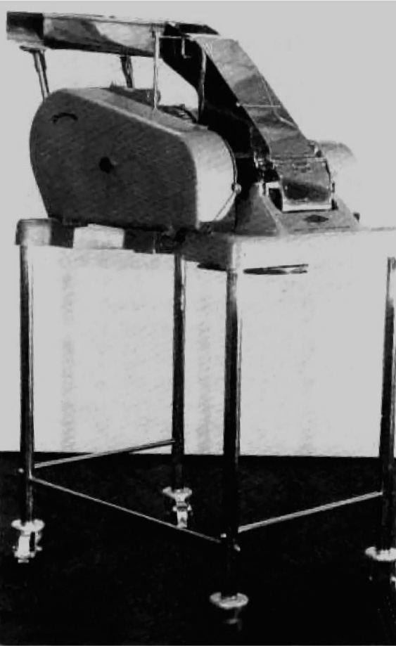
The material to be processed is led via a feed pan to a throat or chute, the design of which may be modified to suit the physical nature of the product concerned. Pulverized material falls through the screen and is collected in drums or other suitable receivers. The speed of the mill may be adjusted, usually between 1000 and 5000 rev per min, and when temperature control is important, as for example, when dealing with thermolabile drugs, the grinding chamber may be water jacketed. For aseptic processing, a model is available which can be dismantled easily for cleaning and sterilizing. The Apex mill and Fitzmill (
Fig. 19.4) are suitable for producing coarse to ultrafine powder (>1
μm diameter) from such varied materials as drugs, roots, herbs glands livers soaps, etc. They can also be listed for size enlargement or granulation of powders as a preliminary to tabletting (see
Chapter 21).
Pin Mills
These rely on the high speed rotation of a series of pins located on a plate which revolves against a similar plate leaving a small clearance for the passage of the drug being comminuted. Typical is the ‘Reddrop-Periflo’ mill.
The upper disc is fitted to the cover while the lower disc rotates, driven by a vertical spindle and gearing. The material is fed in through the centre of the upper disc and is thrown outwards by the centrifugal force of the rotating disc and broken down to fine power by the series of impacts as it passes outwards between the revolving and stationary pins. The maximum pulley speeds of the ‘Reddrop-Periflo’ mill are 1450 on the smaller and 1000 rev per min on the larger sizes. The top cover is removable for cleaning and for changing the discs, which can be supplied in different forms to suit different materials. Discharge is form the bottom of the casing which is connected to a bag, or by a sleeve to a box. Two or three filter sleeves allow the escape of air which is drawn in by the centrifugal action. These mills are adapted for the fine grinding of substances with low melting points, such as resin, soap, sugar, etc. The mill described is the smallest size and has an output of up to 100kg per hr, with a power consumption of 1.5kW. Larger sizes are made with outputs up to 6 tonnes per hr and power consumptions of 30kW.
Ball Mills
In ball mills the material is ground by the impact and friction of a large number of balls in a rotating vessel. Different models vary greatly in size and form. They produce fine powders; the fineness depending on a number of operating variables such
as the speed of the mill, the size, nature, path and load of the balls and the charge of material being handled. A great deal of work has been done on all these aspects over the last few years (
Hukki, 1959;
Riley, 1965). Steel balls are often the most efficient, but they may produce deterioration or contamination of certain acidic products and porcelain, flint, steel, nylon or rubber balls can be employed instead: mills can be of steel or porcelain or may be rubber-lined. There are considerable variations in the recommendations for ball load. With steel balls, a load of about 33 per cent of the mill volume is often used, but for porcelain or nylon balls it may be as high as 55 per cent. Overloading causes the mill to ‘choke’.
The mill speed should usually be between about 50 and 65 per cent of the critical centrifugal speed, i.e. the speed at which, the balls stick to the inner walls of the rotating vessel. This ensures that their motion is that of cascading, i.e. slipping smoothly over each other, rather than being thrown cataracting—or sliding en masse round the walls of the vessel. Generally, the balls should be as small as practicable, consistent with the size of the feed and the arrangements available for straining them from the product; commonly they are 12mm or less in diameter and spherical in shape, though for some purposes ‘cylpebs’ (cylindrical pebbles) are preferred. There appear to be no particular advantages in using balls of mixed sizes, though it has been claimed that they sometimes help to maintain the charge mobility in the mill.
A modification to the conventional ball mill is the Hardinge mill. This has a conical centre section and as the charge rotates, differential centrifugal forces cause the finer particles to move to the discharge end. In this way, the mill operates simultaneously for size reduction and classification. It may be connected also to an air classifier in which a stream of air is passed through the mill, the fines being transported upwards and recovered in a cyclone separator. The principle of closed circuit grinding, thus outlined, is widely used in the pharmaceutical industry, and has the advantages of accelerating the grinding process by continuously removing the fines which otherwise tend to cushion the larger particles, eliminating problems of dust and overheating, and producing a closely graded product free from oversized and undersized material.
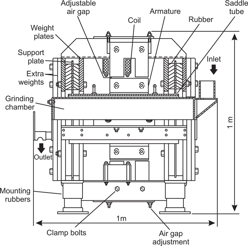
Vibration Mills
Vibration mills are similar to ball mills in that particles of the material are crushed between porcelain or metal balls and the mill body. Here, however, the energy is supplied by vibrating the mill body. The mill is supported on a spring base and is subjected to forced vibrations induced either by rotating out of balance weights or by electromagnetic means.
Laboratory models are usually restricted to one frequency and amplitude of vibration.
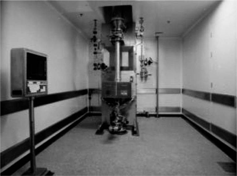
Fig. 19.5 shows details of the GEC VM25 electromagnetic vibration mill which has been successfully employed on a semiproduction scale. Drugs and excipients are readily ground to less than 5
mm diameter, the grinding time being considerably less than is required in normal ball milling. As a result the efficiency of the comminution process in vibration milling is a good deal greater than it is in ball milling (
Rose & Sullivan, 1961).
Micronizing
The process of micronizing or jet milling is now frequently employed in the pharmaceutical industry and involves grinding particles upon themselves (
Dotson, 1962).
Coarse particles are fed into a flat cylindrical grinding chamber of highly resistant stainless or alloy steel; air, or superheated steam at high pressure, is then injected through the jets spaced round the periphery of the chamber, causing the material to circulate at high speed. The violent impacts, which occur rupture the particles and, as a result of the centrifugal motion, classification takes place into different sizes. The larger particles move to the outer grinding zone and the finer ones towards the centre of the chamber, being eventually expelled in the exhaust gas, from which they are recovered with a cyclone collector, which may or may not be an integral part of the equipment.
Commercial micronizers range in size from about 5
cm to 1
m in diameter and have throughputs of up to 2000
kg per hr depending on their size, the characteristics of the product and the size range required. When operated at relatively low jet pressures, e.g. 20–40
lb per in
2 (1.4–2.8
kg/cm
2) their main action is in breaking up aggregates of particles without rupturing the individual crystals and at these pressures therefore, there is little change in the surface area of the powder as measured for example, by nitrogen adsorption. But at higher pressures, 60–80
lb per in
2 (4.2–5.6
kg/cm
2), the individual crystals are ruptured and there is a large increase in surface area. On the whole, micronized drugs are smoother and less irregular in shape than those which have been ground by other methods; particles become increasingly spherical in shape as the period of micronizing is increased.
The mills described in the above section are only a selection of the available types. All have their particular advantages and no one mill will do all that is required in pharmaceutical practice.
The art of milling requires much experience to be able to select the right kind and size of mill to give the required result. While flour milling has been reduced to a practically automatic process, drug milling cannot be done in this way, since each different material has its own distinctive properties and requires special treatment. A powdered drug produced in a ball mill differs from that produced in a micronizer even though both powders may be screened to the same fineness, the difference being due to the shape of the particles, their roughness and their internal pore structure. A fibrous material ground in an Apex mill will give a much more fluffy powder than the same material ground in a ball mill. Substances of a resinous or oily nature should not be subjected to heavy pressures or much heat, as a pasty mass may result; they are better treated in a micronizer or hammer mill, than in a heavy edge runner mill Much heat is produced in the grinding process and this is particularly noticeable in high speed mills, when a current of air passes through the mill, as in closed circuit grinding, the material often loses considerably in weight due to the evaporation of moisture. Powders that have lost weight in this way usually tend to regain it on storage.
In the British Pharmacopoeia, the degree of comminution of materials varies according to the purpose for which they are required, from crushed, e.g. gentian for the preparation of tincture, to very fine, e.g. calomel in injections of mercurous chloride.
Particle size characteristics, particularly in the case of sparingly soluble drugs, have a profound influence on their rate of absorption in the stomach or gastrointestinal tract, and hence on their efficiency when administered orally, Penicillin in a medium of aluminium monostearate plus arachis oil, appears to be most effective when 90 per cent of the particles are smaller than 5
μm. The relatively insoluble sulphonamides attain their maximum antibacterial activity at crystal sizes of about 1
μm or below (
Neuman & Axon, 1961). For insufflations the drug should usually be smaller than about 5
μm.
For the preparation of extracts of vegetable drugs, the grade varies from coarse to fine powder, the components of compound powders are all finely powdered and in the preparation of tinctures, bruised to moderately coarse powders are used. Powders used for extraction by percolation should not contain a large proportion of fines, as this would result in uneven extraction of the material. Coarse and moderately coarse powders, with a minimum of fine powder are most easily obtained by using a high speed impact mill. Materials such as cascara, liquorice, belladonna leaf and root, and ginger are all easily broken down in such mills. When fine powders are required, many drugs can still be broken down in high speed impact mills by fitting finer screens; the finer the screen the slower the process becomes, and with very tough materials the process is very slow.
Fine powders of tough or fibrous materials such as nux vomica or ipecacuanha are often produced in two stages, a preliminary treatment in an Apex mill and a final grinding to the required grade in a ball mill or edge runner mill. Substances which are hygroscopic such as potassium carbonate, or very poisonous such as triturations of the alkaloids, are most easily prepared in closed porcelain ball mills. The fineness of grinding of some drugs produces changes in their properties. For example, the viscosity of mucilage of tragacanth prepared from No. 60 powder will be greater than that prepared from No. 120 powder, both powders having been prepared from the same sample of gum. Tragacanth should therefore never be ground to a finer powder than is necessary. The industrial grades of acacia which sometimes tend to give ropy solutions are often improved by fine grinding. Powders used as absorbents have that property enhanced by fine grinding. Spontaneous combustion sometimes occurs in finely powdered resins and hard soap since the greatly increased surface area accelerates oxidation and produces heat. In the case of soap, it can generally be traced to the quality of the olive oil used in its manufacture, unrefined oil often being the cause.
The colour of powders is affected by the degree of comminution and also by the proportion of particles which are finer than the designated grade. As previously stated, there is a difference between powders of the same grade produced in different mills. Powders produced in ball mills and particularly in edge runner mills usually contain a high proportion of fines which tend to cause a ‘white’ powder to appear ‘whiter’ and affects the tint of a coloured powder.
Other Techniques for Producing Fine Particles
Mention will be made elsewhere in this book of certain other techniques for producing materials in the form of fine particles, but for completeness it will be convenient to give brief details of them here also, since they are widely employed in industry in the preparation and purification of drugs and other pharmaceutical powders.
Precipitation
Precipitation occurs when solutions of materials which react chemically are mixed to form a product which is but sparingly soluble in the liquid, and therefore deposits out. Precipitation is a convenient method for producing solids in a very fine state of subdivision down to 0.1
μm in diameter. It is also widely used as a method of purifying powders since the required product and its impurities will generally be soluble to different extents in the liquid medium that has been employed. Examples of pharmaceutical substances commonly prepared by precipitation are calcium and magnesium carbonates made by treating the respective chlorides with sodium carbonate solution, ammoniated mercury made by adding a solution of mercuric chloride to a solution of ammonia, and yellow mercuric oxide made by adding a warm solution of mercuric chloride to a solution of sodium hydroxide.
Hot, concentrated solutions usually produce heavy, coarse precipitates which can be fairly readily freed from contaminating salts by washing. But the precipitates from cold dilute solutions are usually much finer and it may be difficult to free them from impurities adsorbed on to their very large surface area. In many cases the order of mixing the solutions can influence the type of precipitate obtained. For example when a solution of an iron salt is poured into an excess of a solution of sodium carbonate, iron carbonate Fe2(CO3)3 is produced, but if the procedure is reversed the product will also contain basic salts such as Fe(HCO3)3, Fe(OH)(CO3)2, etc., which may be difficult to remove.
Crystallization
Crystallization differs from precipitation in that the product deposits from a supersaturated solution rather than from a liquid in which it is insoluble. The basic steps in crystallization are first to achieve a supersaturated solution, then to provide nuclei on to which the material can deposit in the form of microcrystals, a few hundredths or even thousandths of a micron in size and finally to allow these microcrystals to grow up to normal crystal dimensions so that they settle to the bottom of the containing vessel and can be separated from the supernatant liquid. Crystals will only grow if the solution is supersaturated and the rate of growth is proportional to the degree of supersaturation (
Dunning, 1961).
The shapes and sizes of the crystals formed are markedly dependent on the conditions under which the crystallization is carried out. For example, griseofulvin crystallized from acetone has a different form from the same drug crystallized from benzene or chloroform. A derivative of an organic acid used in an insufflation has large needle shaped crystals when precipitated from hot alcohol and cubic crystals when precipitated from acetone—alcohol mixtures. Crystallization, like precipitation, is also widely used as a method for removing impurities from pharmaceutical products before they are incorporated in capsule or tablet formulations. The need for lengthy grinding in machines can often be avoided by correctly choosing the conditions of the crystallization itself to produce the drug directly in the state of fineness that is required.
Crystallization equipment is most readily classified according to the method employed for producing the supersaturated solution. Supersaturation can be achieved by cooling, by evaporation of the solvent, by a combination of cooling and evaporation and by salting out, i.e. adding another solute to the solution to reduce the solubility of the substance in question. Equipment in commercial use includes tank crystallizers, agitated batch crystallizers, the Svenson Walker Crystallizer, the Krystal and other vacuum crystallizers and details of their design and operation will be found in textbooks of chemical engineering (
Badger & Banchero, 1955).
Sieving and sifting
A feature of the modern pharmaceutical industry is the increased use that is being made of materials in a fine state of subdivision. Numerous methods have been developed for sifting powders and determining their particle size. Of these sieving is undoubtedly the most common, being applicable to practically all powders from about 40μm upwards.
Sieving
In the UK, the British Standard Sieve is extensively used both for scientific work on powders and for separating them into fractions on a commercial scale. In Europe the German DIN (Deutsche Industrie Normen) is widely used. But different standards are used for German, American and other sieves. To state that a sieve has a certain mesh is meaningless unless the diameter of the wire constituting the mesh is also specified. This will determine the size of the opening. Clearly the opening will always be smaller than the measurement suggested in the ‘mesh designation’ (
Tables 19.1 and
19.2).
Table 19.1 Wire mesh sieves as per BP
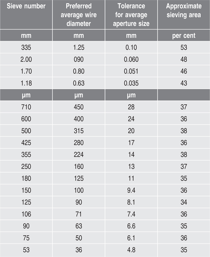
Table 19.2 Perforated plate test sieve
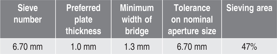
Sieves for pharmacopoeial testing are of wire cloth woven from brass, bronze, stainless steel or other suitable wire and are not coated or plated. The wires are of uniform circular cross section. There must be no reaction between the material of the sieves and the substance being sifted.
According to IP 2007, sieves conform to the specifications given in
Table 19.3.
Table 19.3 Specification of various sieves as per IP
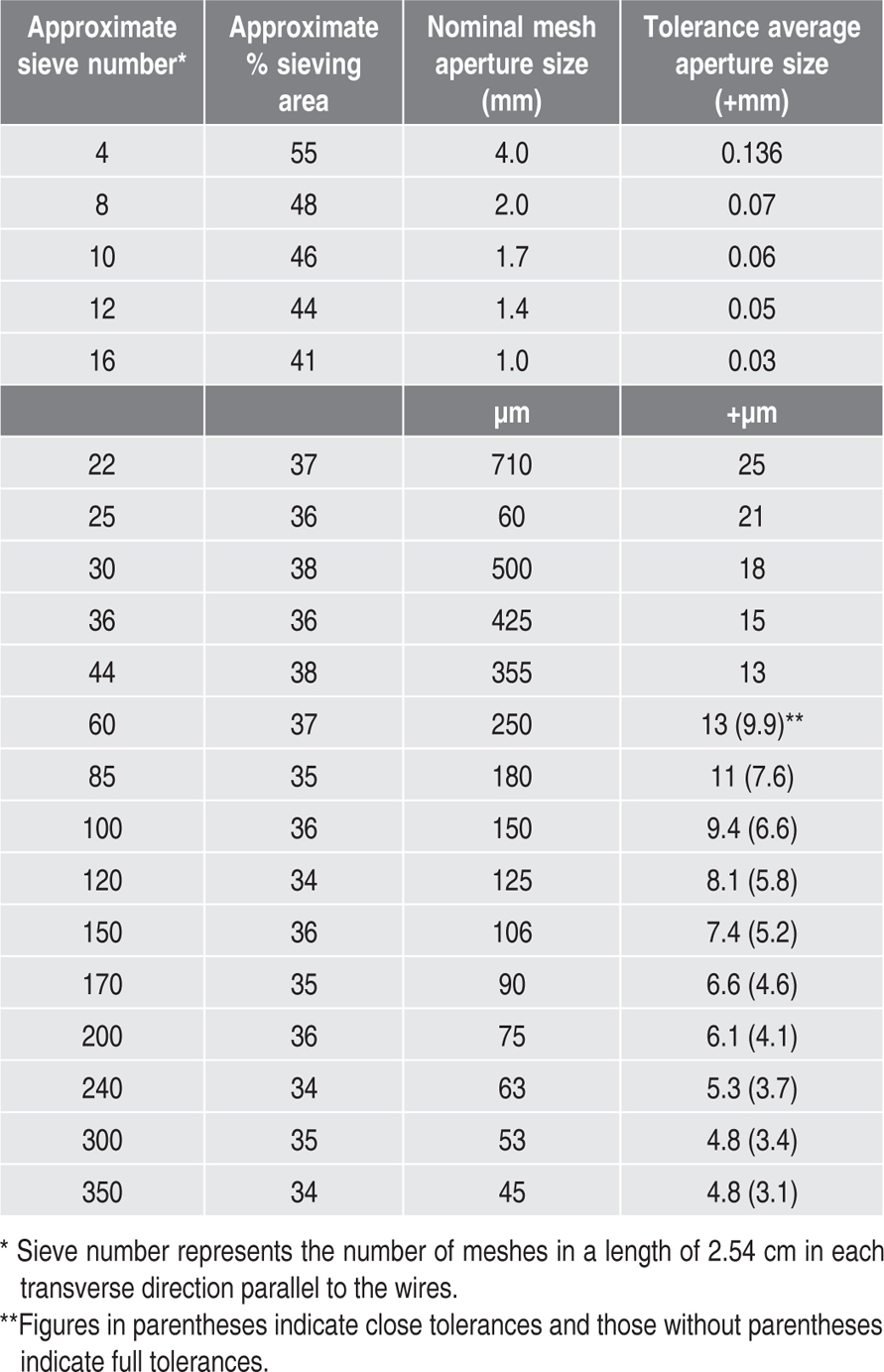
Sieve specifications according to BP and IP are similar in certain denominations like sieve number, tolerance for average aperture size and approximate sieving area except that in BP a sieve is also specified in terms of preferred average wire diameters whereas in IP nominal mesh aperture size is mentioned. Along with that, the measures of the sieve number in both BP and IP are different, as shown above in
Tables 19.1 and
19.3.
To obtain reproducible results in a particle size analysis it is necessary to adhere closely to the detailed procedure given in
British Standards 410 (1969). The powder under test is passed through a number of sieves of increasingly smaller mesh size and the weight remaining on each sieve is measured. The method of shaking the sieves is important; for rapid sieving it is usual to use a mechanical shaker that imparts gyratory and vibratory movement to spread the material over the whole of the mesh. Errors can arise if the sieves are overloaded or if insufficient time is allowed for the particles to pass through (
Heywood, 1963).
The Alpine Airjet Sieve
In recent years the Alpine Airjet Sieve has been developed to extend the range of conventional sieves which tend to block at particle sizes below about 80μm. The action of the sieve depends on a jet of air instead of mechanical vibration. Its purpose is to fluidize the powder, thereby preventing blocking of the mesh and at the same time cushioning the particles from impact with the mesh which, in the case of soft powders, artificially produces fines.
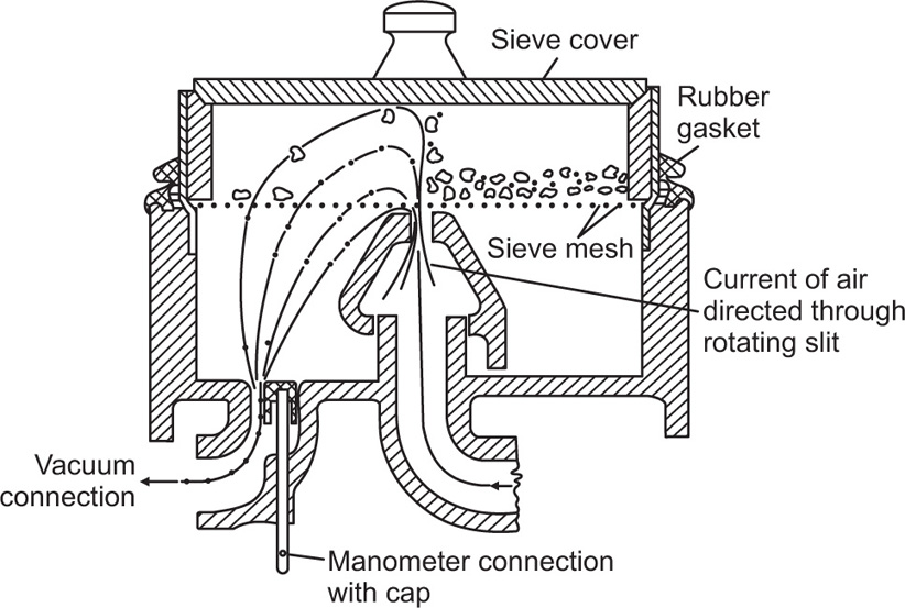
The apparatus shown in
Fig. 19.6 consists essentially of a metal housing into which the sieve mesh is fitted. Powder is placed on the mesh which is then covered by a close fitting lid and is fluidized by an upward jet of air directed on to its lower surface through a rotating slit. A vacuum is simultaneously created in the interior of the housing so that the undersized powder is sucked through the sieve into a paper filter from which it can be recovered if required.
Having checked that the upper edge of the rotating slit is level with the upper edge of the housing, the finest sieve is fitted into the machine and the plastic sealing ring drawn downwards until an airtight seal is obtained.
About 10g of the material under examination is carefully weighed and spread onto the sieve and the cover placed in position. The slit is set into rotation and the suction adjusted until the manometer reads 200mm. Sieving is continued for 2min, the residual powder is weighed, transferred to the next sized mesh with a fine brush and the process continued until the sieve analysis is complete.
Airjet sieving has a number of advantages over the more conventional method. It is rapid, produces closer and more reproducible size cuts, is not subject to the clogging which occurs in hand or vibration sieving at small sizes in particular, and probably gives a truer result since there is less tendency for fines to be formed as a result of the sieving itself. Against these advantages, however, must be set the fact that Airjet sieves have a relatively small capacity which makes them unsuitable for handling large quantities of powders. They are thus primarily used for determining the particle size range of a powder rather than for classifying it.
Classifiers and Sifters
Most commercial classifiers and sifters are based on the principle of sieving (
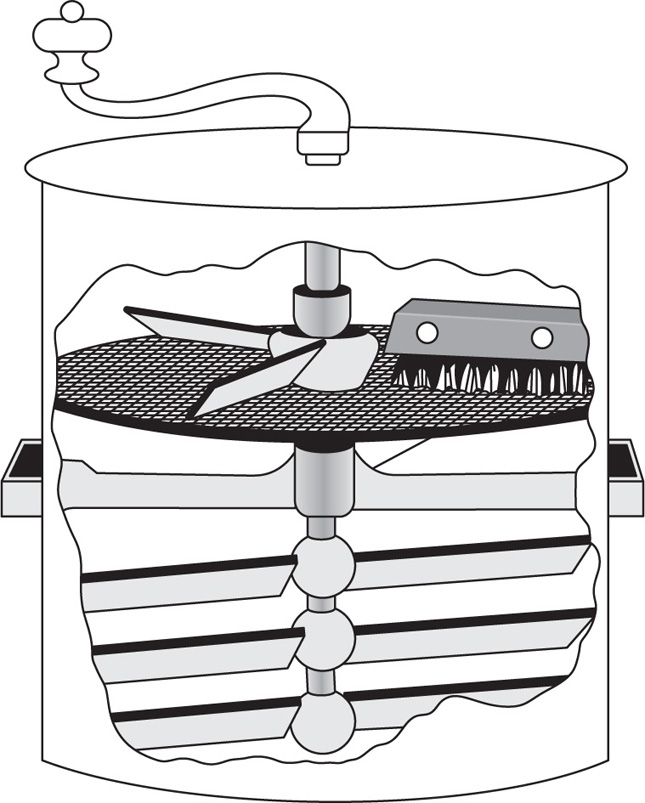
Cremer & Davies, 1957). Thus in the Pascal turbine sifter there is a cylindrical screen which is divided into two or three compartments, in each of which there is a turbine beater, which drives an air current through the screen and carries the fine powder with it. This is drawn off from the base of the machine, the air is recirculated and the coarse material is discharged from a spout at the side. Brush sifters employ brushes to separate the fine and coarse particles on the sieve mesh and are useful for greasy or sticky powder such as waxes and soaps. One design has three circular brushes mounted on a triangular structure. The sieves are mounted on a delivery funnel of stainless steel or enamel and the whole unit (
Fig. 19.7) is supported on a wheeled trolley for ease of movement.
In recent years there has been an increasing demand for pharmaceutical powders like griseofulvin, and aspirin in an extremely fine state of subdivision, i.e. less than 10
μm and this has necessitated the use of what are essentially centrifugal classifiers. One example is the Cutrock classifier (
Goodridge et al., 1962). It consists of three rotating discs mounted in a cylindrical chamber. The drug flows from a buffer along a vibrating feeder and is drawn into the classifier by a stream of air passing along an axial inlet. It then flows radically outwards between discs.
The rotation of the discs causes the air stream to spin with the result that the larger particles circulate in an annular gap between the edge of the discs and the casing of the chamber, while the smaller ones are expelled through the exit and can be collected in a bag. By appropriately choosing the speed of operation of the machine, it is possible to collect only the particles smaller than a particular size and return the rest for further grinding until they meet the specification that has been set.
For larger scale classification the Alpine Mikroplex and the Hosokawa types are useful. These again employ the centrifugal principle and have rotating blades which can be set at different angles to achieve separations ranging from 3 up to about 50μm diameter. Depending on the material being handled and the particle size of the fraction to be collected, the outputs from these machines are between about 50 and 5000kg per hr.
Determination of Particle Size
There are a number of methods available for measuring the sizes of particles in a powder (
Edmundson, 1967) and in principle all would yield the same result if the particles were uniform in size, spherical, smooth and nonporous and of equal density. In fact, however, real powders contain particles of a range of sizes, shapes, densities and porosities and the value obtained thus depends to a considerable extent on the method of measurement and on the conventions used for defining particle size. The particle size may be defined in terms of the dimensions and shape of the particle, e.g. a mean diameter based on direct observation, or one may refer to a mean diameter calculated from the volume of the particle or its surface area (
Heywood, 1963). Particles having similar shapes may be compared for size by microscopic examination or sieving; particles with similar hydrodynamic properties by sedimentation or elutriation and particles with similar porosities and surface characteristics by gas permeability or gas adsorption. The size ranges covered by some of these different methods are indicated in
Table 19.4.
Table 19.4 Size ranges covered by different methods for measuring particle size |
| Method |
Useful range (μm) |
| Sieving |
Above 33 |
| Optical microscopy |
0.2–100 |
| Electron microscopy |
0.005–1 |
| Sedimentation and elutriation |
2–50 |
| Gas permeability |
5–100 |
| Gas adsorption |
0.005–20 |
| Coulter counters |
1–100 |
Microscopy
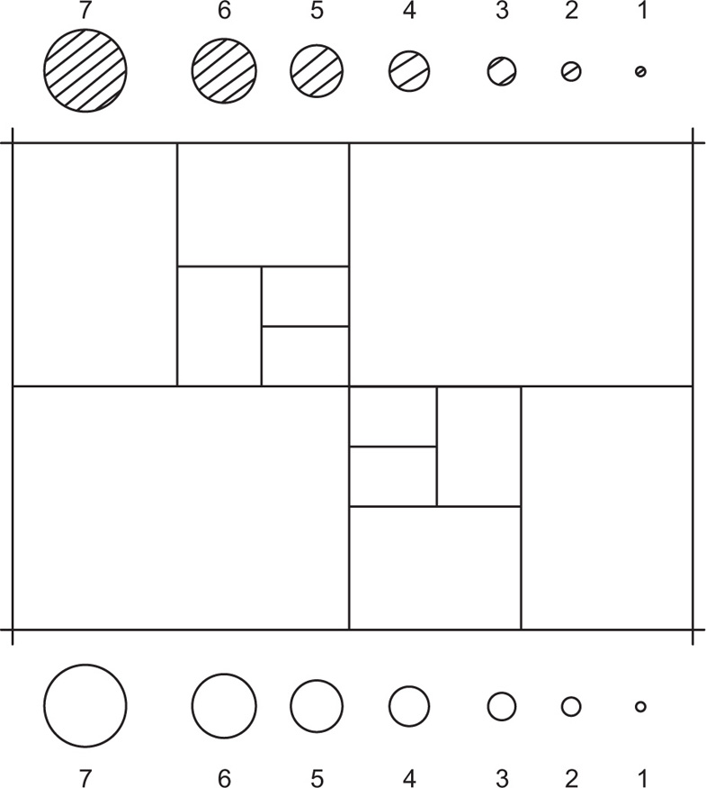
A representative portion of the powder is placed in a glass slide and viewed through a microscope. The images are compared with reference circles of known size inscribed on a graticule and in this way the relative number of particles of each size present in the sample may be determined. In most powders the frequency of occurrence of particles increases rapidly as their size diminishes and it is therefore necessary to measure large numbers of particles—200 to 300—to ensure a representative count. The actual procedure to be adopted has now been standardized and is described in British Standards, the standard graticule being illustrated in
Fig. 19.8.
The percentage by weight of particles in each size range, i.e. between consecutively numbered circles on the graticule, is denoted qr, thus:

where
Nr is the number of particles of this size per unit area of the graticule,
dr is their mean diameter and the symbol Σ denotes the summation of all the products of

.
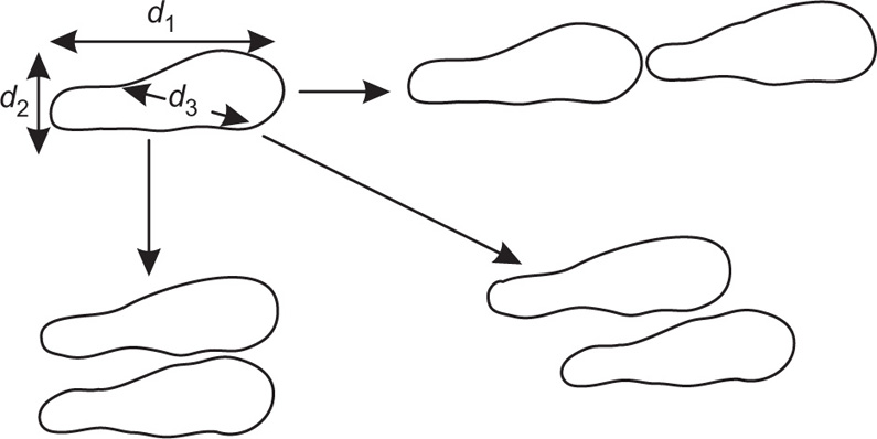
In cases where the powder contains particles of irregular, nonspherical shape, double image microscopy is useful. The microscope is fitted with a beam splitting device (
Timbrell, 1959), which is situated between the objective lens and the eyepiece. This forms two identical images of any particular particle which is in the field of view. The images are brought into edge to edge contact along different diameters, as illustrated in
Fig. 19.9 and the length of each diameter
d1,
d2 and
d3 is obtained in turn by reading off the shear that has been applied to the beam splitting device to get the two images into edge to edge contact.
Sedimentation Method
This is based on the measurement of the rate at which particles of the powder settle out from a liquid in which they have been dispersed. The technique is widely employed and can be extended down to sizes of about 0.5μm under special circumstances by using a centrifuge to accelerate the settlement.
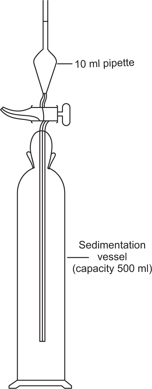
In the incremental method (
British Standards, 1963) the powder is suitably dispersed in the liquid contained in a tall vessel, as shown in
Fig. 19.10. Ten ml samples are withdrawn at predetermined times from a known depth below the surface and the weight of powder present in each sample is determined either by evaporating the liquid and weighing the residue, or by some suitable assay method.
In order to calculate the range of particle sizes present in each sample, use is made of Stokes’ law. This applies strictly only to dilute dispersions where the concentration of solid is less than 2 per cent (w/w).
This can be written as:
where
V is the velocity of fall of a particle,
h is the depth in cm below the surface from which the sample is withdrawn after
t s,
d is the diameter of the particle in cm,
ρ is the density of
the material in g per ml,
ρ′ is the density of the liquid in g per ml,
g is the gravitational constant 981
cm s
−2,
η is the viscosity of the liquid in poise.
Knowing all the terms in this equation, d, the diameter of the largest particles present at the depth h cm after t s can be calculated and this sets the upper limit of size in each 10-ml sample of liquid that has been withdrawn.
For the calculation it is convenient to write:
where η and t are now expressed in centipoise and minute, respectively.
The cumulative percentage W of material smaller than size d is given by:

where w is the weight of the solid in the withdrawn sample, V is the total volume of the sedimentation vessel (usually about 1 litre), Ws is the weight of the withdrawn sample (usually about 10g), Vρ is the volume of the pipette in ml, and is plotted against particle size to give a cumulative distribution curve in the usual way.
The cumulative method of sedimentation analysis is carried out with a sedimentation balance (
Stairmand, 1947).
As before, the powder is uniformly dispersed in a liquid but now a continuous record is kept of the weight that settles on a balance pan which is immersed in the liquid column. For the purpose of computation:

where w is the weight of particles that settle in time (seconds) and W is the fraction by weight of particles greater than a particular diameter in microns, which is calculated by Stokes’ law from a knowledge of the height of the suspension above the balance him, the density of the particles and the density and viscosity of the medium. For accurate results it is necessary to observe a number of precautions when using a sedimentation balance. These include ensuring its freedom from vibration, accurate temperature control to eliminate convection currents and the employment only of dilute suspensions less than about 2 per cent w/w.
Gas Permeability
The gas permeability of a powder provides a measure of its surface area and if it is assumed that the particles are all of equal size and spherical in shape, then their mean diameter can be evaluated.
In the Lea and Nurse method (
Orr & Dallavalle, 1959), dry air is forced at constant pressure through a bed of the powder under investigation. In the Rigden method, which has been adapted from it, air is allowed to escape from a reservoir through the powder bed and the time for the pressure to fall from one specified level to another is measured.
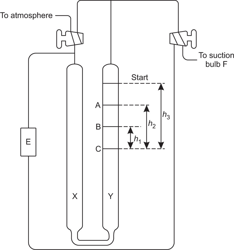
The Rigden apparatus is shown schematically in
Fig. 19.11. The two ends of the cell E containing the powder are connected to the two ends of a U tube containing a nonvolatile oil. The equilibrium level of the oil is at C. The oil is sucked into one arm Y of the manometer by means of the bulb F and as it returns to the equilibrium level, it forces air through the powder bed, The time taken for a given volume of oil to travel between the starting line to mark A or B on the manometer is measured and the specific surface is calculated from the Kozeny equation, This can be written:
where S is the specific surface in cm2g−l, ε is the porosity, A is the cross-sectional area of the powder bed, η is the gas viscosity in poise, L is the length of the powder bed, β is the atmospheric pressure in cm of liquid of density ρg cm−3, g is the gravitational constant in cm s−2, V is the volume of the reservoir, h2 is the final reservoir pressure in cm of liquid, h1 is the initial reservoir pressure in cm of liquid, d is the density of the powder sample in g cm−3, t is the time in s for the air pressure to fall from h1 to h2.
For a given apparatus and porosity the equation reduces to:

A convenient, semiautomatic piece of equipment employing the same principle, is the Fisher subsieve sizer in which air at a constant pressure is forced through the powder bed. The pressure drop is read off from a water manometer and by means of a calculator chart is converted into an average value of particle size.
Gas Adsorption
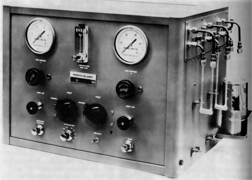
The amount of gas that will be adsorbed by a powder also provides a means of determining its total surface area, and this type of measurement is conveniently carried out with the Perkin–Elmer shell sorptometer (
Fig. 19.12). Basically the apparatus consists of two valves for controlling the flow of nitrogen and helium gas.
These flow through a cold trap then through the reference arm of a detector unit, then through an adsorption tube containing a known weight of the sample which has previously been freed from adsorbed gas by subjecting it to a high vacuum, and finally through the measuring arm of the detector. The amount of nitrogen adsorbed by the powder at a series of different partial pressures of nitrogen is obtained by continually measuring the thermal conductivity of the emergent gas stream, and the surface area per g of the sample, is then obtained from the BET equation.
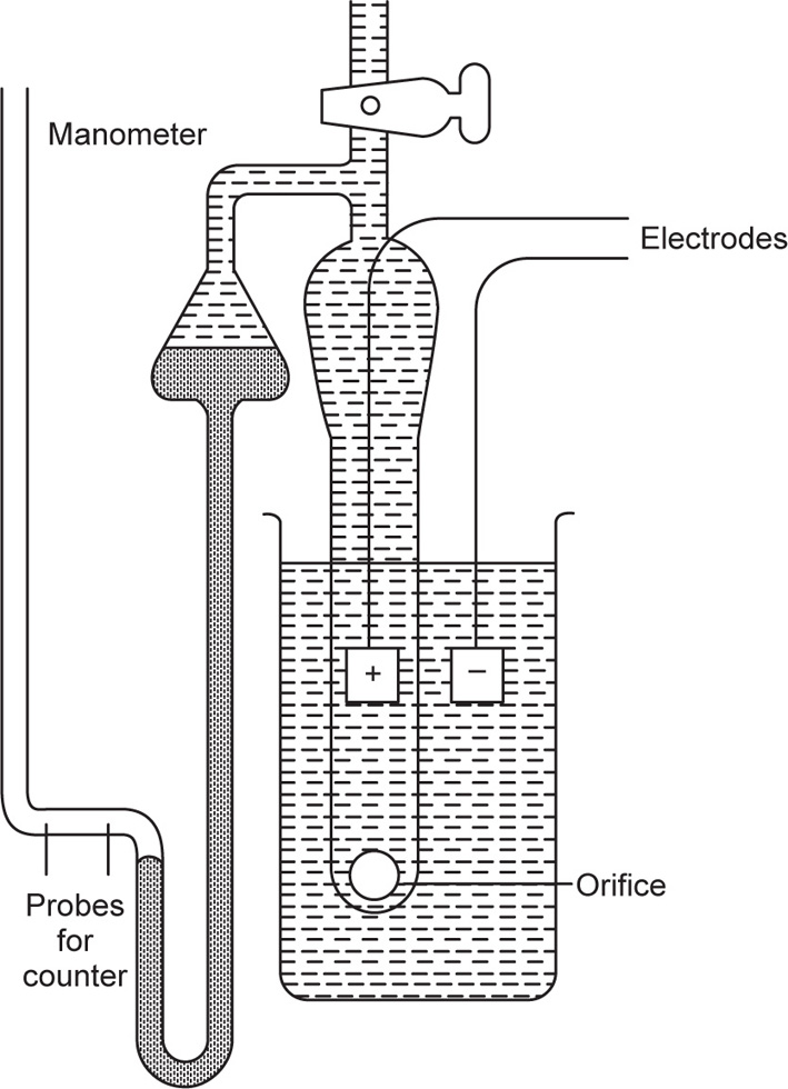
Coulter Counter
This apparatus is coming increasingly into use in pharmacy for determining the particle size of powders (
Edmundson, 1967) and depends on the ability to prepare a suspension of the sample free from floccules or aggregates. The suspension is made up in a suitable electrolyte solution, e.g. NaCl, and is then drawn through a small orifice, having an electrode on each side,
Fig. 19.13. As each particle passes through, it displaces its own volume of electrolyte within the orifice and momentarily increases its electrical resistance. The resulting voltage pulses are proportional to the particle volume; they are amplified, scaled and counted and yield a particle size distribution curve extending, under ideal circumstances, down to about 0.2
μm. On the whole the results agree fairly well with those obtained by sedimentation. But on occasions there can be considerable discrepancies with the microscopic results. This is probably due to the difficulty encounted in some cases in achieving complete dispersion of the particles.
Particle Shape
Even to describe a moderately irregularly shaped body in exact mathematical terms is a matter of great complexity and in practice it is more usual to simplify the procedure by assuming that all particles can be considered as ellipsoids, whose axes are
al >
a2 and
a3 such that
al >
a2 >
a3. The ratio
a1/
a2 is defined as the elongation ratio and
a2/
a3 as the flatness ratio. If
a1 is similar to
a2 and
a2  a3
a3, the elongation ratio is about unity, the flatness ratio is large and the particle is described as disc shaped. If
a1 a2 and
a2 is similar to
a3, the elongation ratio is large, the flatness ratio is about unity and the particle is described as acicular (needle-shaped). If
a1 a2 a3, then both the flatness and the elongation ratios are large and the particle is described as ribbon shaped (
Neumann, 1967).
A more refined way of defining shape (
Heywood, 1963) is to include in these ratios a term which also takes into account the geometrical form, e.g. a prism, ellipsoid, tetrahedron, to which the particle most closely approximates, but even this procedure breaks down in the case of complex shaped particles, for example, those containing bends, re-entrant angles or cavities.
In order to specify the ‘shape’ of a powder, it is necessary to examine a large and representative number of particles, usually under the microscope, and calculate an average value for the
elongation and flatness ratios. Alternatively, the shape may be defined simply as the ratio of the average particle diameter, as determined in some direct way, like sieving or microscopy, to the average particle diameter determined in an indirect way like sedimentation or gas permeability. Each pair of methods will give rise to a different shape factor.
The shape of particles is often affected by the method employed for preparing them. Spray dried products; for example, tend to be spherical in shape, as do micronized products. The angularity of products seems to increase with the type of mill used for reducing them to powder form in the order micronizer, ball mill, pin mill and hammer mill (
Rose, 1961).
As in the case of particle sizes, the shapes of particles have an important influence on certain of their properties which are relevant in pharmaceutical practice. In the dry state, irregular particles tend to be less free flowing than spherical particles, but may be able to pack together more closely giving a higher bulk density. The rheological properties of pharmaceutical suspensions are also affected by the shapes of the particles that they contain.
Handling Properties
Sliding and Flow
With the increasing employment of materials in powder form, not only in pharmacy, but also in many other branches of technology, it has become necessary to examine what, for a better term may be designated the handling properties of powders. This means the way in which powders slide in pipes or chutes, pack down when stored in silos, flow from hoppers and form into heaps when tipped or dumped. Pharmacists have long recognized that some powders are inherently more cohesive than others, that fine’ grade griseofulvin, for example, is less free flowing than spray dried lactose, so that it cannot be sieved through a 30μm sieve even when its individual particles, as measured by gas adsorption or sedimentation, may be as small as 5μm.
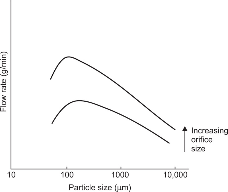
If one separates a powder or granular mass into its different sizes and then measures the rate at which these flow through a particular size of orifice, one finds that a graph can be plotted between flow rate and particle size, as shown schematically in
Fig. 19.14.
There are two regions where the orifice blocks, one where the particle diameter exceeds about one fifth of the diameter of the orifice, the other at the very small particle size, below about 100μm. Here they form into a dome over the orifice, rather like bricks over a doorway.
This sort of behaviour is characteristic of virtually all materials, though the position and height of the, maximum in the curve, and the position where blocking occurs, vary from one material to another, being dependent on such properties as the density, shape, roughness of the particles concerned.
It is convenient to label material that will pass through an orifice as free flowing, but material which will not, even though its particles are very much smaller than the orifice, as cohesive. A number of techniques are available for studying powders in both the free flowing and in the cohesive size range.
Methods for Free Flowing Powders and Granules
1 The angle of friction
α may be defined as the angle to which a particular surface must be elevated from the horizontal before the powder begins to slide upon it. It is measured conveniently by placing the material on a chute, which is pivoted at one end and raised at the other by means of a screw. Clearly the value obtained for a will depend on the roughness of the surface. But it also depends on the thickness of the powder bed. In general, the thicker the bed and the more it has been packed down during preparation the greater the value of
α (
Jones & Pilpel, 1966).
2 The so-called angle of repose of a powder,
θ, is the angle of elevation to the horizontal at which the powder commences to slide upon itself. Numerous methods have been devised for measuring it (
Pilpel, 1965;
Neumann, 1967). Thus the powder may be allowed to flow out of a funnel to form a conical heap and
θ calculated from the base radius
r and hypotenuse
h of the cone by substituting into the expression: cos
θ =
r/h.
Alternatively, the cone may be formed by placing an open-ended cylinder on a base of the same radius, filling it with powder and then raising it slowly to leave a conical heap behind. Both these methods yield a so-called three-dimensional angle of repose. The two-dimensional angle of repose can be obtained with similar equipment to that used for the angle of friction, but noting this time the angle of elevation when the surface layer of powder begins to slide on the rest of the bed. For this purpose it is clearly necessary to use a chute with a rough surface to prevent the whole powder bed sliding off it.
The angle of repose varies within about ± 2° depending on the experimental method employed; other factors affecting its value are the since of the particles in the powder, their shape and roughness. The angle decreases fairly regularly with particle size in the range 200–2000
μm and can be expressed by:
where A and B are constants for any particular material and DP is the particle size concerned.
The presence of fines, additives and moisture can produce considerable changes in the value of the angle of repose and for this reason its measurement is usefully employed as a means of monitoring the quality of powders being produced in batch or in continuous processes. For example, if one observes an increase in the angle of repose, the powder may have become damp or may now contain an increased proportion of fine sizes.
3 The most direct method for free flowing powders is simply to measure the rate at which they emerge through the orifice of a suitable container or hopper. A large number of investigations of this type have been reported (
Pilpel, 1965;
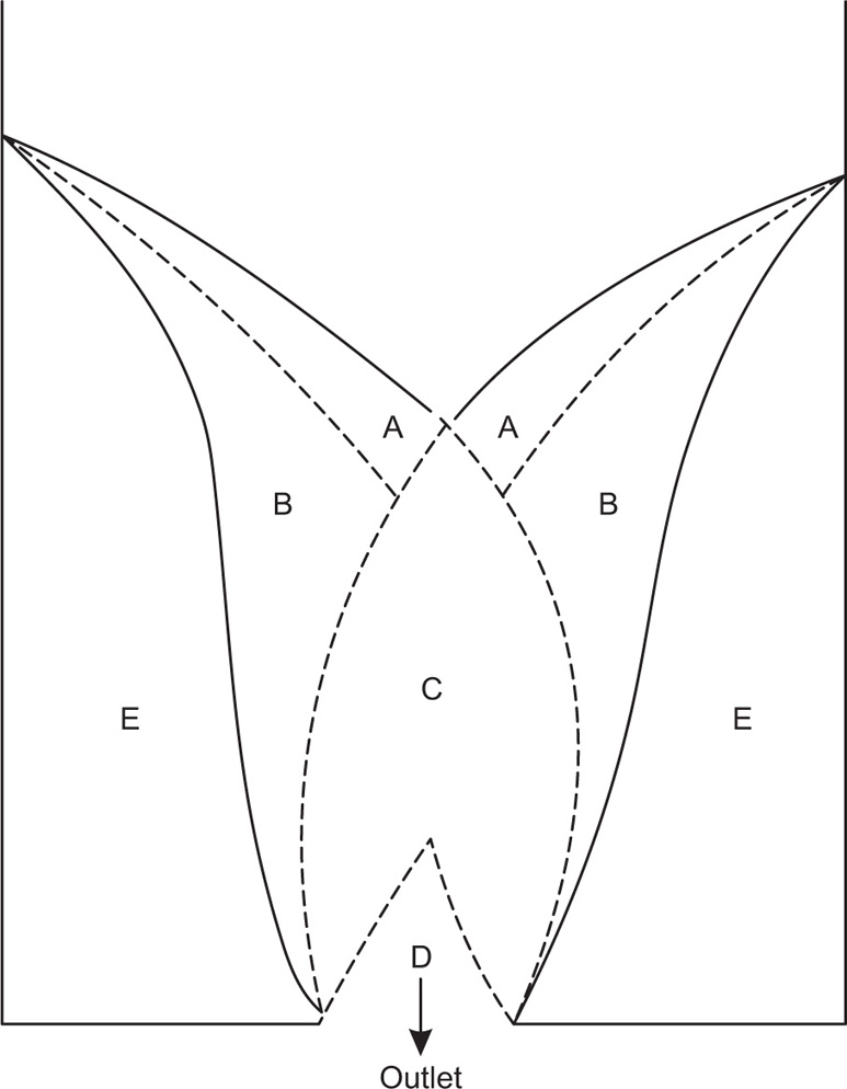
Neumann, 1967). One rather unexpected finding is that whereas the rate of flow of a liquid through an orifice is directly proportional to the head of liquid, in the case of a powder, the head height has practically no effect on the rate. This arises in part because of the complex movement of the powder in the immediate vicinity of the orifice, as shown in
Fig. 19.15.
Outside the trumpet-shaped region above the hole, denoted E, the powder is at rest. In region A the particles are sliding rapidly over region B, which in turn is sliding slowly over region E. Particles from A and B slide into C down slopes which are inclined to the horizontal at angles greater than the angle of repose and then move rapidly downwards and inwards into D. Once in D they accelerate and emerge in a stream which is noticeably narrower than the orifice. This phenomenon is referred to as the vena contracta.
The most important single factor controlling the rate at which a powder emerges from a circular horizontal orifice appears to be the orifice diameter Do and one can therefore write:

where W is the flow rate in g/s, Do is the orifice diameter in cm and n is a numerical term, which for many materials lies between 2.5 and 3.2. Other factors controlling the flow rate include the particle shape, size, density and roughness and the geometry of the containing vessel. The equation:
where
A and 1/
n are functions of these factors and
g is the acceleration due to gravity, has been successfully used for predicting the flow rate of different materials, not only when they have been sieved into close size cuts, but also when they contain a range of sizes in the free flowing region, In this case one employs a geometrical mean particle diameter for the purpose of evaluating the terms
A and 1/
n (
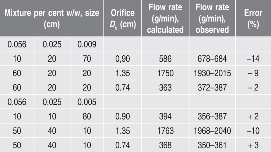
Jones & Pilpel, 1966). Some typical figures illustrating the agreement between flow rates as measured and those predicted from the equation are shown in
Table 19.5.
Table 19.5 Ternary mixtures of magnesia granules
Methods for Cohesive Powders
The problem of expressing in quantitative terms the handling properties of nonfree flowing materials is more difficult and has recently been reviewed in detail (
Pilpel, 1971). One earlier technique (
Hawksley, 1947) is to mix into the powder coarser particles of sand until the mixture just starts to flow through a particular size hole and use the amount of sand required as a measure of the cohesiveness of the powder but the method is not very sensitive.
The split plate method (
Dawes, 1952) involves dredging the powder to form a loose bed on a split, roughened flat surface, one half of which runs on ball bearings. On slowly tilting, the bed separates and if one knows the cross-sectional area of the bed A and the mass of it in the half that has separated, m, then the tensile strength is given by:
β being the angle of tilt that has caused the bed to separate.
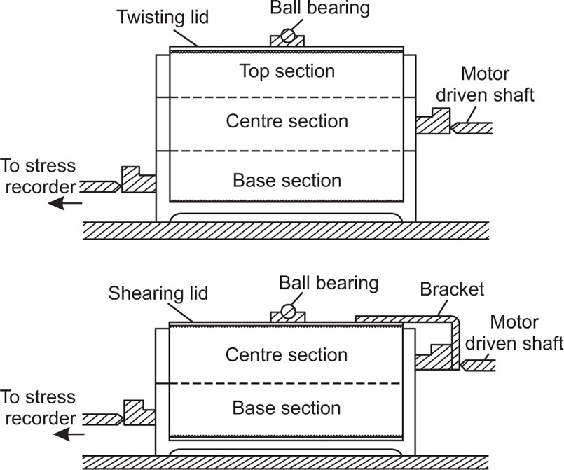
From both the theoretical and the practical point of view, probably the most satisfactory method for measuring the cohesiveness of fine pharmaceutical powders is the shear box method (
Jenike, 1961;
Ashton et al., 1965). The apparatus
Fig. 19.16 consists of a cylindrical brass cell which is divided horizontally into a base section, a centre section and a moulding ring, the three being aligned and held in position while filling with powder by means of three vertical pins.
The base section can be moved along steel rails by a motor-driven shaft at a constant speed of 1.25mm per min and this causes the centre section of the cell to bear against a device which records the shear stress.
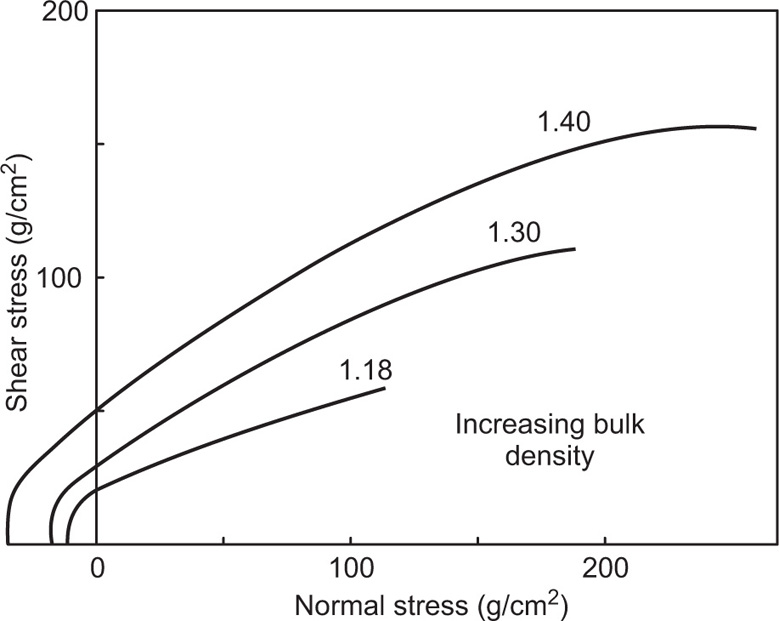
Having filled the cell with powder and established the number of twists that must be applied to the lid correctly to consolidate the specimen, the tests consist of applying various normal loads to the lid and measuring the shear stress needed to split the bed horizontally. The results are plotted as shown in
Fig. 19.17 to give a series of yield loci, each appropriate to the value of the bulk density achieved during the initial consolidation of the specimen. The slope of the yield locus is the internal angle of friction of the powder and its intercept on the ordinate is its cohesiveness.
Data of this type are useful for predicting the way in which pharmaceutical powders are likely to behave during manufacture and during such processing operations as transportation, sieving, granulation, storage and tabletting. A highly cohesive powder tends to compact on storage, flow with difficulty and thus cause blocking of pipes and orifices. It tends to be difficult to sieve in to fine fractions as it balls up on the sieve mesh. It may also prove difficult to mix in the dry state with excipients and other ingredients as the first stage in compressing into tablets or filling capsules.
Mixing of Powders and Particulate Solids
Because of its antiquity and apparent simplicity, it was for a long time assumed that the subject of mixing and blending powders did not require scientific study. But in the last few decades serious limitations in the empirical approach have become apparent as a result of the increased speed of industrial operations and the increased degree of automation in many pharmaceutical firms.
Mixing is one of the commonest pharmaceutical operations and occurs in the preparation of many types of formulations. The simplest examples are compounded powders administered as such, e.g. ipecacuanha and opium powder. These may contain natural drugs and medicinal chemicals in varying proportions according to their respective potencies. Mixing is also an intermediate stage in most tablet making processes.
The ease with which different substances will blend to a reasonably homogeneous whole varies considerably, being dependent on various physical properties of the individual components and on their relative proportions. Obviously it is easier to mix equal weights of two powders of similar fineness and density than to incorporate a small proportion of a fine powder in a large mass of a coarse, denser material. Apart from density and particle size, the stickiness of the additive is also important and it may require prolonged mixing effectively to distribute lubricants, wetting agents, etc., into tablet granules.
Mixing is sometimes achieved by feeding two or more materials simultaneously to a mill, if both require grinding. In other cases mixing is accomplished by kneading, and the equipment modified accordingly. In pharmaceutical operations, mixing is usually a batch wise process, although a batch may be as large as 1 tonne. Equipment for continuous mixing is available from the food and other industries, but has only recently been used in pharmacy.
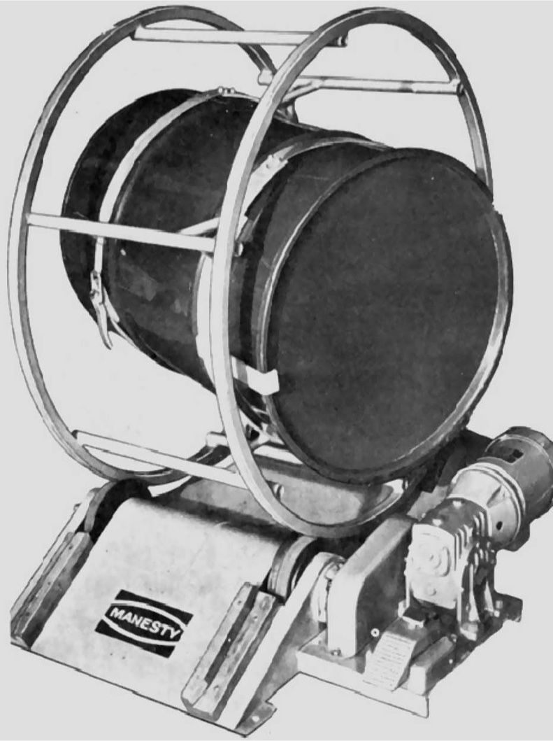
The simplest mixing machines are adapted from the old manual method of heaping materials on the ground and then repeatedly cutting and piling them. One method suitable for
materials the granular or crystalline structure of which might be damaged by more vigorous agitation is the tumbling barrel.
It comprises a box or drum in which the powders are mixed by slow rotation. A very simple method of mixing is to place the drum on rollers so that the ingredients within perpetually cascade over one another. Large bulks of mixed powders and powdered drugs, e.g. nux vomica, jalap, etc., which need to be sampled for assay and adjustment of strength, must be thoroughly mixed if the samples taken are to be representative. For quantities of powder of 500
kg or more mixing drums of the type illustrated in
Fig. 19.18 are used.
A more efficient design is that of the double cone blender, which is a shallow drum with conical ends which is rotated so that the powder flows from one cone to the other. A further advance on this design in the Y cone blender in which one end is conical, while the other consists of two cylindrical ‘legs’. As the blender rotates, the moving mass of powder is continually divided and recombined while entering and leaving the ‘legs’. Conical blenders are made in stainless steel or in transparent plastic, the smaller models take a charge of about 20kg and rotate at 35 rev per min and the larger ones a charge of about 1 tonne, rotating at about 15 rev per min.
For quite a range of pharmaceutical products, particularly those containing cohesive ingredients which tend to ball up into aggregates or ingredients which, as a result of their differing flow properties, tend to segregate or demix, agitation mixers are generally more satisfactory than tumbling mixers.
They consist essentially of a stationary shell with a horizontal or vertical agitator moving inside it. The agitator may take the form of blades, paddles or a screw.
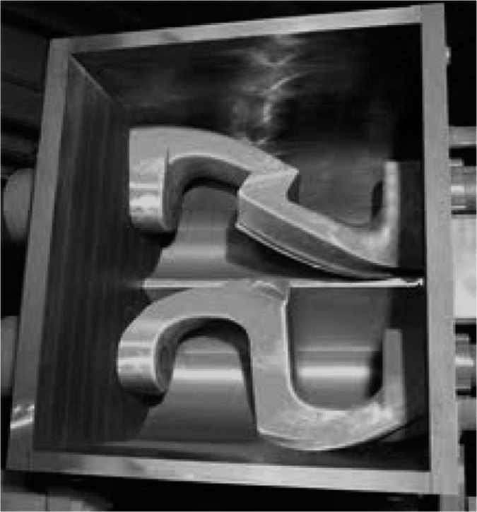
The preliminary mixing of stiff pastes, such as toothpastes requires slow speed mixers which must be very robust to overcome the friction due to the viscosity of the mixture. The mixer in
Fig. 19.19 is a typical example, where two ‘Z’ blades of polished steel revolve in opposite directions and at different speeds to each other resulting in efficient kneading of the paste.
A recent development in powder mixing is the employment of compressed air or fluidization. The substances to be mixed are introduced through a weight or volume dosimeter into a conical vessel, fitted at the bottom with a distributor, through which compressed air is introduced (
Anon, 1966). Air emerging from the distributor at a speed of several hundreds metre per second, causes the powder or granules to spiral upwards. Considerable turbulence occurs in the outer region of each spiral and this is responsible for the mixing action.
Air mixers are fabricated in capacities up to about 50m3 and achieve their action in a matter of a few minutes, in comparison with up to several hours in more conventional machines. On the other hand, such mixers are not very suitable for sticky or cohesive powders, for very dense substances or for mixtures which contain ingredients having substantially different densities, which cause them to segregate.
Ideally, perfect mixing could be said to have occurred when each particle of one material was lying as nearly adjacent as possible to a particle of another material. But in practice a convenient definition of the degree of mixing of a powder is its standard deviation σ. For a mixture of two components this can be defined by:

where
x and
y are the proportions of the minor and major constituents and
N is the number of particles in the sample taken. Mixing of pharmaceutical powders should be continued
until the amount of the active drug that is required in a dose is within ± 3 SD of that found by assay in a representative number of sample doses. To achieve this it is clearly necessary to make
N large by milling the ingredients to a sufficient degree of fineness (
Train, 1960).
Granulation of Powders
In pharmaceutical practice, two main methods are used for preparing tablets from powders which, in their original state, are neither free flowing nor compressible. These are slugging and wet granulation. Quite recently fluidized bed methods have also been described. (See also
Chapter 21.)
Slugging involves strongly compressing the powder between rollers and then breaking it up. The resulting granules are fed into a tabletting machine and because of the double compression to which they have been subjected, now produce satisfactory tablets.
Wet granulation can be done in several ways (
Rumpf, 1962). The drug, binder, excipients, etc., are mixed together with sufficient water to produce a dough and this is then pressed through a sieve mesh, either mechanically, or by hand. Alternatively, the dough may be extruded through a multiple spout extruder or ‘mincing’ machine. After drying, the granules are lightly shaken on a B.S. No. 22 sieve, to free them from adhering fine material that may still be present. The Apex and similar mills, e.g. the Fitzmill, which have already been described in connection with comminution of solids, can also be applied to the granulation of powders by feeding in the materials as a dough and using a slow operating speed and a coarse grade of mesh during the breaking process.
Another method of granulation by spray drying is to form the powder into a slurry with water and then spray it downwards against a rising current of hot air in the form of fine droplets. The water evaporates and one is left with rounded, light and porous granules which, when made in this way, generally flow freely. They have a minimal tendency to block the hopper or clog the dies of multipunch tablet making machines (Reff et al., 1961).
Recently a bowl method has been developed for granulating pharmaceutical powders which, though still in the development stage, has commercial potentialities. The materials to be granulated are placed in a large copper or stainless steel bowl, which is mounted on the shaft of a driving motor and tilted at an angle of about 30° to the horizontal. They are made to tumble by revolving the bowl at a speed of about 30 rev per min at the same time spraying in a fine mist of water, or a dilute solution of a suitable binder, such as polyvinyl pyrrolidone or gum. As the powder becomes moist, the particles start to agglomerate and by correctly choosing the speed of rotation, the amount of liquid, and the processing time, they can be made to grow up to any desired size. (In some cases, tumbling of the powder needs to be assisted by fitting shallow baffles in the interior of the bowl.) A stream of warm air is then directed into the bowl, which dries off the granules and the final drying is done by spreading them on flat trays in an oven and heating at about 80°.
Granules prepared by this method are generally smoother and more uniformly spherical than those obtained by the other methods that have already been described.
It is appropriate to conclude this chapter by referring briefly to one or two other aspects of powder science that are relevant in the practice of pharmacy, in the context of the handling properties of powders.
Transport
The transport of materials in bulk by pneumatic methods, employing air slides and pipelines, is coming into increasing use because of its obvious advantages over the conventional method of carrying in sacks, cartons or other containers. Losses due to spillages or torn containers are reduced, contamination and dust formation are minimized and savings can be achieved by reduced labour costs and the lower freight rates that apply to the transport of materials in bulk.
An air slide consists of a chute with a porous metal base through which air is passed at about 1lb/in2 (0.07kg/cm2) and 5ft (1.5m)/min. This partly fluidizes a fine powder, reducing its angle of friction very nearly to zero so that it can flow down the slide even when this is almost horizontal. In this way, the powder can be transported a long distance horizontally.
In a pneumatic pipeline system on the other hand, a high velocity stream of air is passed through the conveying line and the powdered materials are fed into it from storage hoppers or from mechanical conveyors, being delivered into the appropriate receptacles which are vented to the atmosphere through suitable dust filtration equipment.
For the design and satisfactory operation of pneumatic conveying systems, it is necessary to know a good deal about such properties of a powder as its density, particle size distribution, cohesiveness, angles of friction and repose, and fluidization characteristics. The same properties are clearly of relevance to the pharmacist in the formulation of powdered insufflations, where the patient has to inhale a fine powder directly into the lungs.
Dust Control
The control of dust is an important aspect of modern pharmaceutical practice, not only for the purpose of maintaining the sterility of products, but also for preventing the loss and widespread dissemination into the air of powdered drugs, which might have an adverse effect on the health of factory workers and other members of the community. Dust is a potential hazard as a source of explosions and fires and in reports from the Chief Inspector of Factories, starch and dextrin dusts, in particular, have been mentioned as dangerous in this respect.
The main methods used for controlling dust in the pharmaceutical industry are filtration, inertial separation and electrostatic precipitation (
Green & Lane, 1957;
Hammond, 1958).
In filtration, air which contains dust is sucked or blown through some suitable material whose pores are sufficiently
small to retain the particles of solid. Materials used for the purpose include paper, felt, wool, cotton wool and nylon. Filters often take the form of pads or panels fitted to the walls and windows of buildings. But there is also a large variety of filter bags, stockings and cabinets, etc., which can be attached to particular machines where dust is being produced, thereby preventing it from escaping into the atmosphere.
Inertial separators are exemplified by cyclones, in which air is caused to spiral through a coneshaped vessel. Due to centrifugal force, any particles of dust that it contains are thrown outwards to the walls of the cyclone and then slide down to a hopper from which they can be subsequently withdrawn.
Cyclones are particularly suitable for attaching to machines in which large amounts of dust are being produced; they form an integral part of the design of certain mills and mixers.
Finally, electrostatic precipitators consist of a number of earthed tubes between which are stretched fine metal wires charged to several thousands of volts d.c. The high potential difference between the tubes and the wires ionizes any particles of dust that are being carried by air streaming over the precipitator and the dust is deposited on metal plates from which it is collected periodically.