Chapter 21
Tablets
Advantages of Tablet Medication
Disadvantages of Tablet Medication
Types and Uses of Tablets
Granulation
The Tablet Compression Cycle
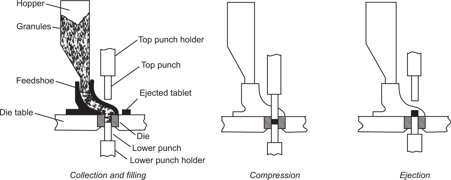
Fig. 21.1 The compression cycle for a single-punch tablet machine.
Essential Granule Properties
Granulation Processes
Moist Granulation
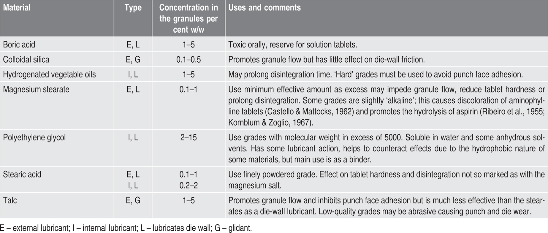
Table 21.1 Some diluents used in tabletting |
|
| Diluent | Uses and comments |
| Calcium Phosphate BPC | Absorbent diluent. Increases granule BPC density but some grades are abrasive. |
| Calcium Hydrogen Phosphate USP | Used for direct compression formulations. |
| Colloidal silica | Small proportion used as an absorbent diluent or to improve granule flow by glidant action. |
| Anhydrous Dextrose BP | Absorbs moisture at high relative humidity—see BPC. |
| Dextrose (spray dried) | Useful for direct compression formulations but absorbs moisture at high relative humidity. |
| Lactose BP | Inert, tasteless, odourless, inexpensive and gives granules by moist granulation which have good tabletting properties. Incompatible with primary amines (Duvall et al., 1965). |
| Lactose (spray dried) | Used for direct compression formulations but tablets may assume a brown tinge on storage (Brownley & Lachman, 1963). Is also incompatible with primary amines. |
| Lactose (anhydrous) | Used for direct compression formulations. Care should be taken to prevent moisture uptake. Is also incompatible with primary amines. |
| Mannitol BP | Dissolves readily and has a ‘cooling’ effect in the mouth. |
| Microcrystalline cellulose | Mainly used for direct compression formulations; has some lubricant and disintegrant effect and may improve the behaviour of granules made by other methods. |
| Sodium Chloride BP | Oral tablets containing this substance must be dissolved in water before administration to avoid gastric irritation—see BP. Usually reserved for the formulation of solution tablets. To avoid binding during compression, dry thoroughly and compress while still Warm. |
| Starch BP | Small proportion of dried starch may be used as an absorbent excipient but its main use is as a disintegrant. |
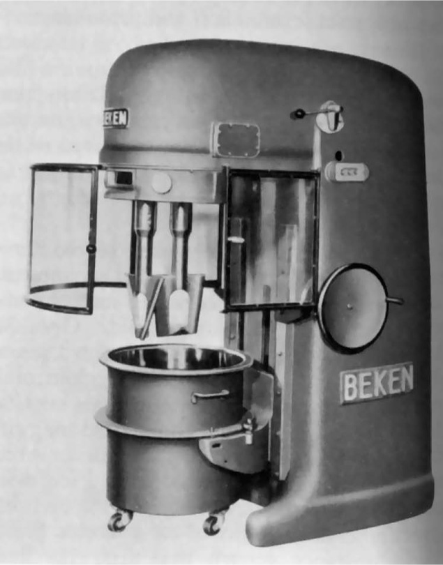
Fig. 21.2 The Beken change pan mixer with working capacity of about 0.1m3. The machine is shown with the pan lowered and the guard open (Beken Engineering Ltd.).
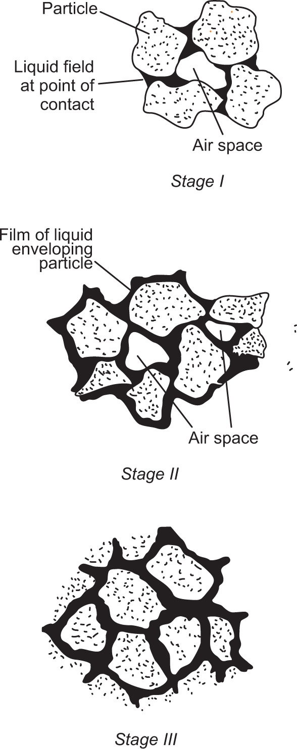
Fig. 21.3 Stages in the moistening of a powder.
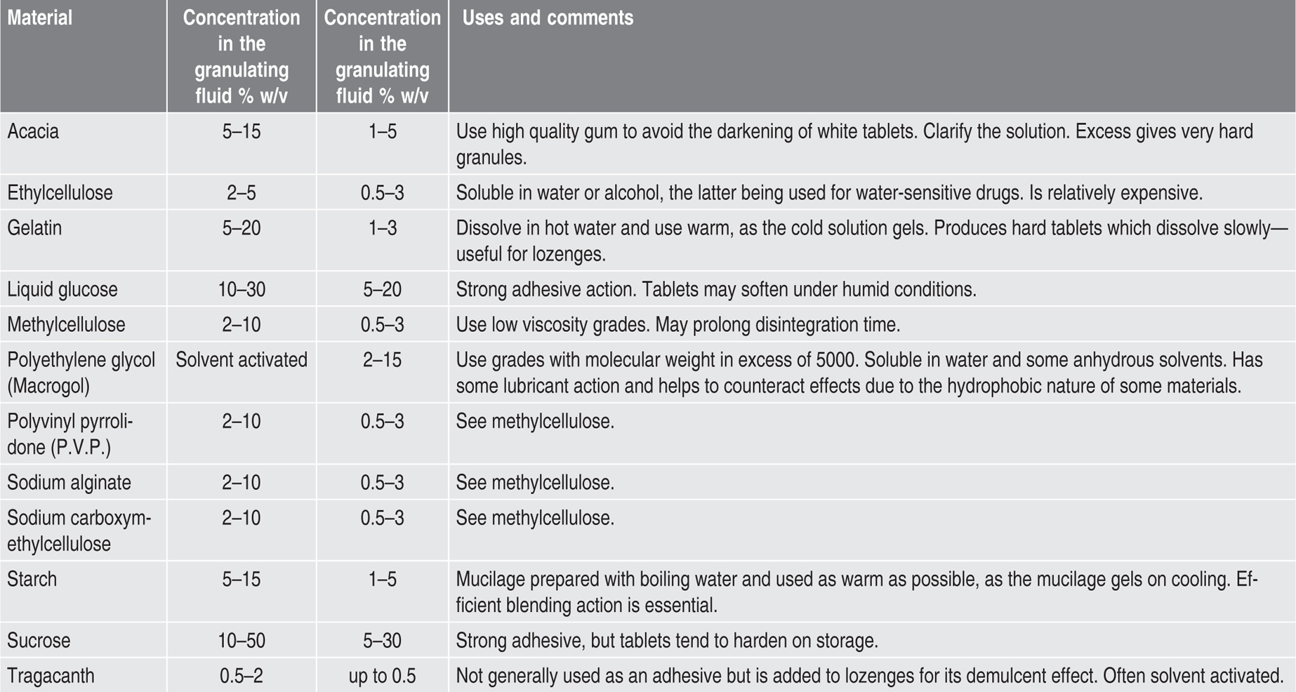
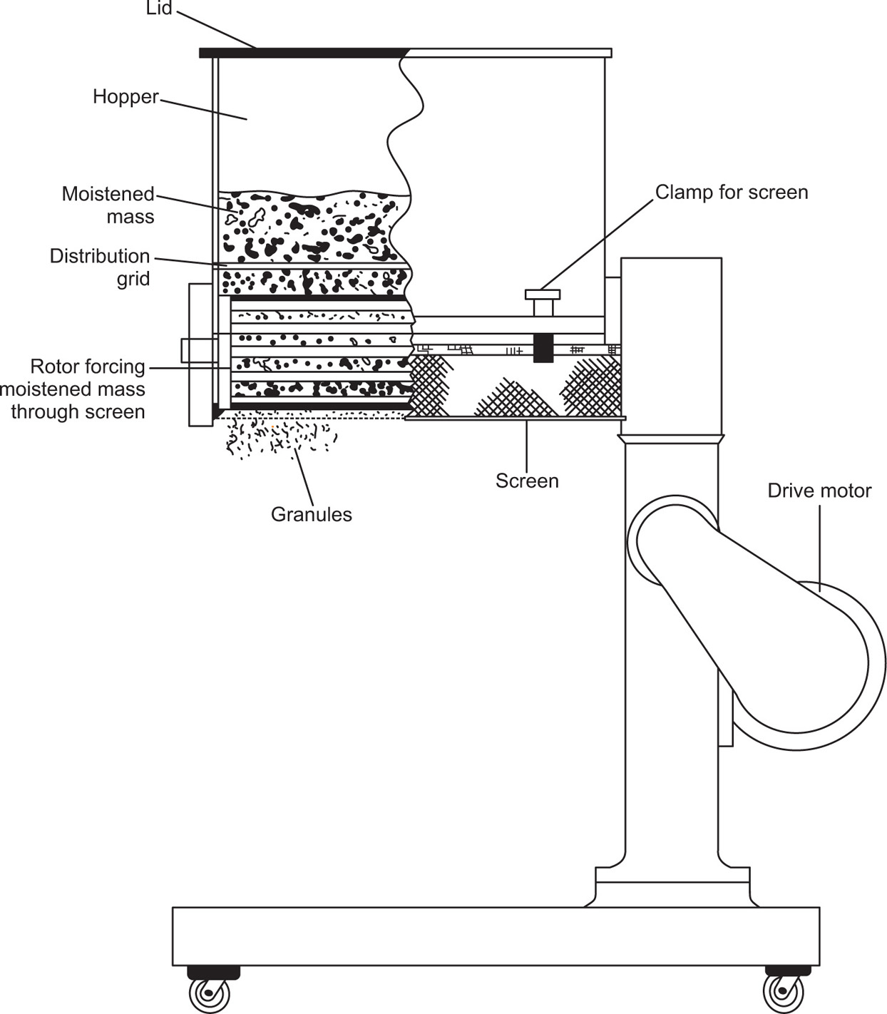
Fig. 21.4 The oscillating granulator.
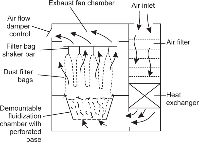
Fig. 21.5 The fluid-bed drier.
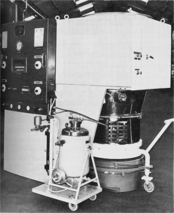
Fig. 21.6 The Calmic fluid-bed granulator. The programming panel may be seen top left. This controls application of granulating agent from the pressure vessel (centre bottom) to the material in the fluidizing chamber.
Preliminary Compression or Slugging
Dry Granulation
Flavours, Lubricants and Disintegrants
Flavours
Lubricants
Disintegrants
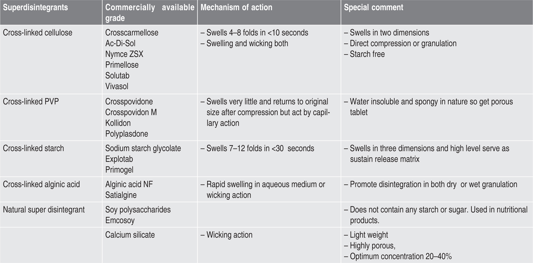
Table 21.5 Disintegrants used in tabletting |
||
| Material | Concentration in the granules per cent w/w | Uses and comments |
| Alginic acid | 2–10 | Burster which may prove better than starch for ‘difficult’ materials (Berry & Ridout, 1950). May be incorporated prior to moistening to improve disintegration. If added to the dry granules, avoid finely powdered grades as these form a coherent gel on the tablet surface and may prolong disintegration time. |
| Magnesium aluminium silicate | 1–10 | Burster. Veegum is one variety |
| Methylcellulose | 2–10 | Burster. Use medium viscosity grade in a not too fine powder |
| Microcrystalline cellulose | 1–10 | Has some lubricant properties, higher concentrations used as dry-binding diluent |
| Sodium lauryl sulphate | 0.1–0.5 | Wetting agent which improves penetration of the tablet pore system by aqueous liquids. Will counteract the water-repellent effect of, for example, phenothiazine and the stearate lubricants. May minimize the increase in disintegration time which often occurs as tablets age |
| Starch | 2–10 | Burster. Potato and maize starch are usually considered superior to the other varieties. Part may be incorporated prior to moistening |
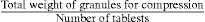
The Compressing Weight
Dry Granulation
| Codeine phosphate | 20.00mg |
| Stearic acid, in fine powder | 0.06mg |
| Potato starch | 0.60mg |
| Spray dried lactose | 39.34mg |
| Compressing weight | 60.00mg |
Preliminary Compression
| Per tablet (mg) | For 100,000 tablets (kg) | |
| Aspirin, in fine powder | 300 | 31.00 |
| Anhydrous citric Acid | 30 | 3.10 |
| Calcium carbonate | 100 | 10.33 |
| Saccharin sodium | 3 | 0.31 |
| Talc | 4 | 0.41 |
| Theoretical weight of ingredients | 437 | 45.15 |
| Weight of granules after slugging and rescreening | – | 44.30 |
| Weight of talc added prior to final compression | – | 0.80 |
| Total weight of granules for final compression | 45.10 |
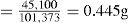
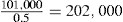
Moist Granulation
| Medicament | 101.0kg |
| Adhesive granulating fluid | 10.6kg |
| Theoretical weight of mass | 111.6kg |
| Actual weight of moist granules | 111.1kg |
| Weight of granules after drying | 104.6kg |
| Weight of granules after screening | 104.3kg |
| Screened granules | 104.3kg |
| Disintegrant | 8.0kg |
| Lubricant | 0.5kg |
| Weight of granules for tabletting | 112.8kg |
Production of Tablets
The Single Punch Tablet Machine
Assembly
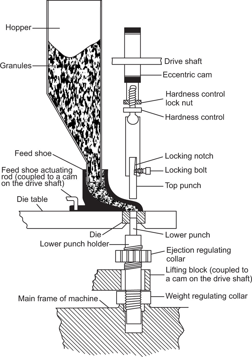
Fig. 21.7 Main operating parts of the single-punch tablet machine.
Adjustments
Operation
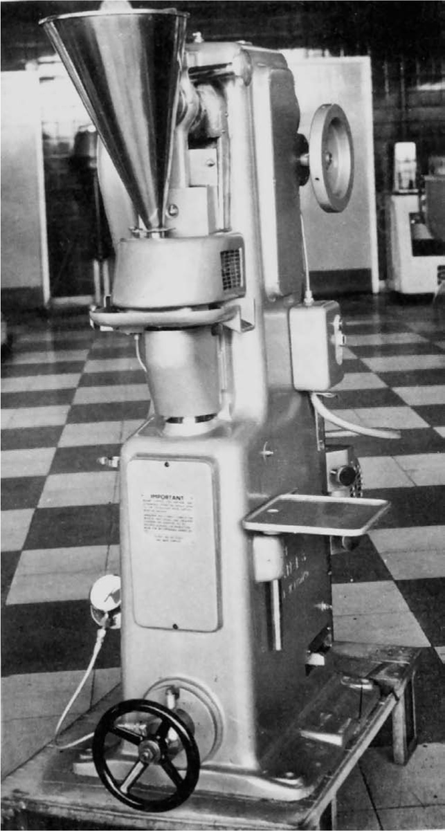
Fig. 21.8 Power-driven single-punch tablet machine. The top punch and the bottom punch holder are enclosed by a safety screen. The value at which overload occurs is indicated by the gauge bottom left.
The Rotary Tablet Machine
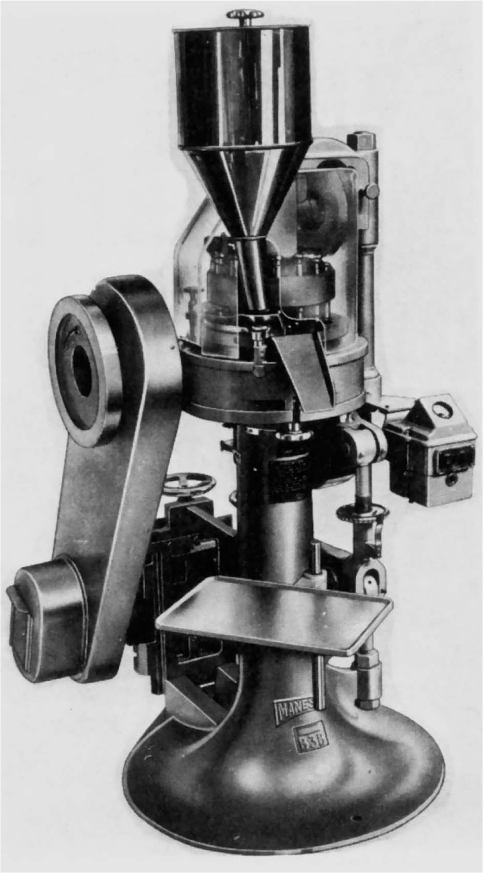
Fig. 21.9 Medium duty 16-station rotary tablet press. The upper turret and punches are visible beneath the plastic dust screen. Manesty Machines Ltd.
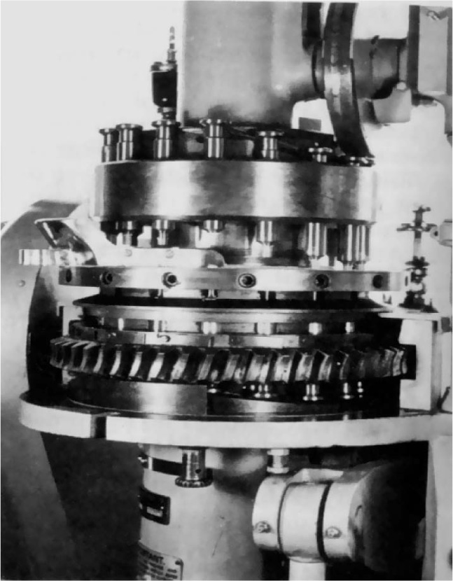
Fig. 21.10 16-station rotary tablet press. The perspex screens and hopper and lower guard have been removed to show the upper and lower turrets and die table. The upper and lower cam tracks and the upper pressure roller are also visible.
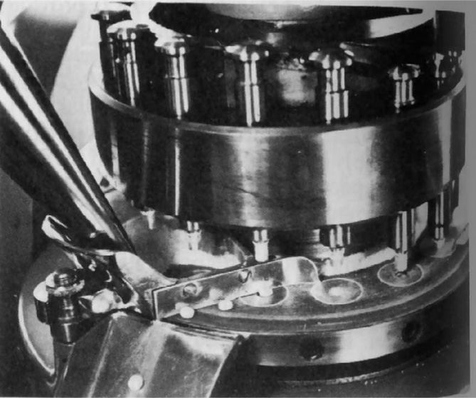
Fig. 21.11 Close-up view of rotary press. The outlet of the hopper may be seen (left) feeding granules into the feed frame. Ejected tablets are being directed towards the collection chute bolted to the end of the feed frame. The upper cam track for lifting the top punch clear of the feed frame is also visible.
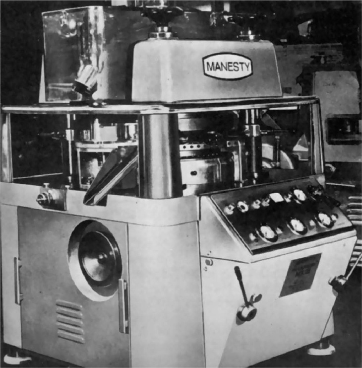
Fig. 21.12 69-station rotary tablet machine. Manesty Machines Ltd.
Developments in the Design of Rotary Tablet Machines
Granule Flow
Die Filling
Removal of Air
Multilayer Tablets
Punches and Dies
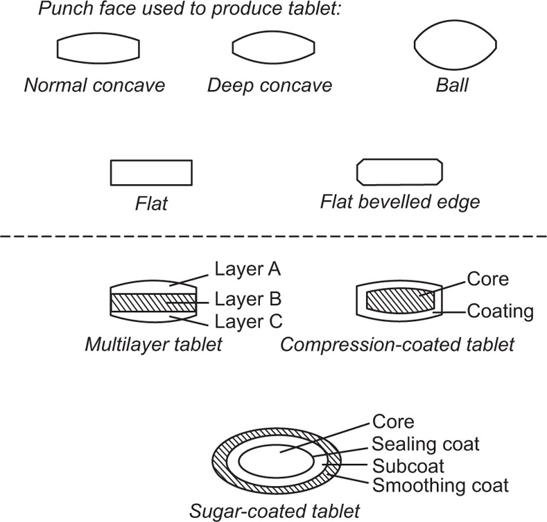
Fig. 21.13 Tablet profiles and structures.
Tabletting Problems
Binding in the Die
Picking and Sticking
Capping and Lamination
Excessive Weight Variation
Fissured or Pitted Surface
Soft Tablets
Protracted Disintegration
Mottled Tablets
Variation of Medicament Content
Drug Instability
Tablet Coating
Pan Coating
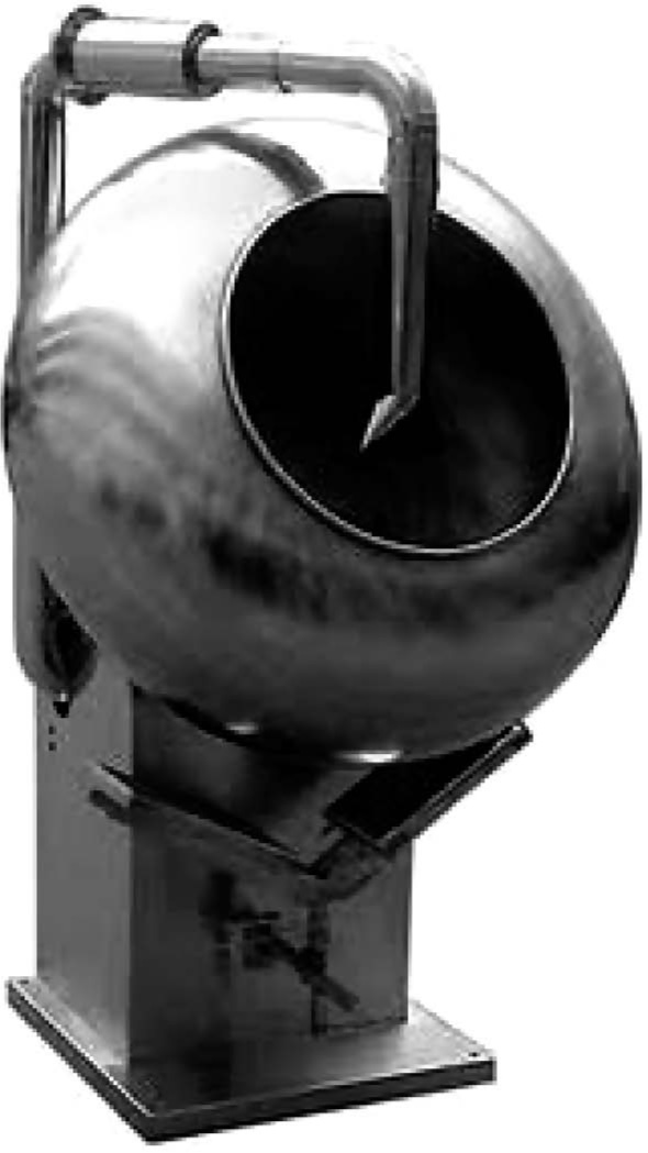
Fig. 21.14 Production model pan coating machine. The diameter of the bowl is about 1m. Courtesy: Vanguard Pharmaceutical Machinery
Sugar Coatings
Film Coating
Enteric Coating
Automated Pan Coating
Fluid-Bed Coating
Compression Coating
Compression Coating Machines
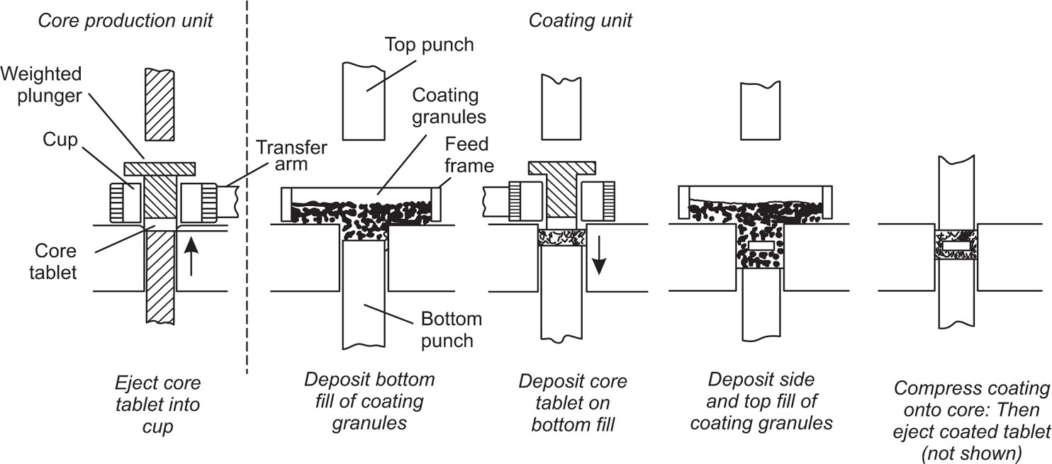
Fig. 21.15 The compression coating of tablets.
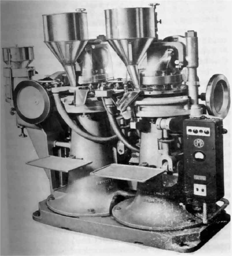
Fig. 21.16 Compression coating machine. The core tablet formed by the left hand unit is carried by the central transfer unit to the coating press or the right.
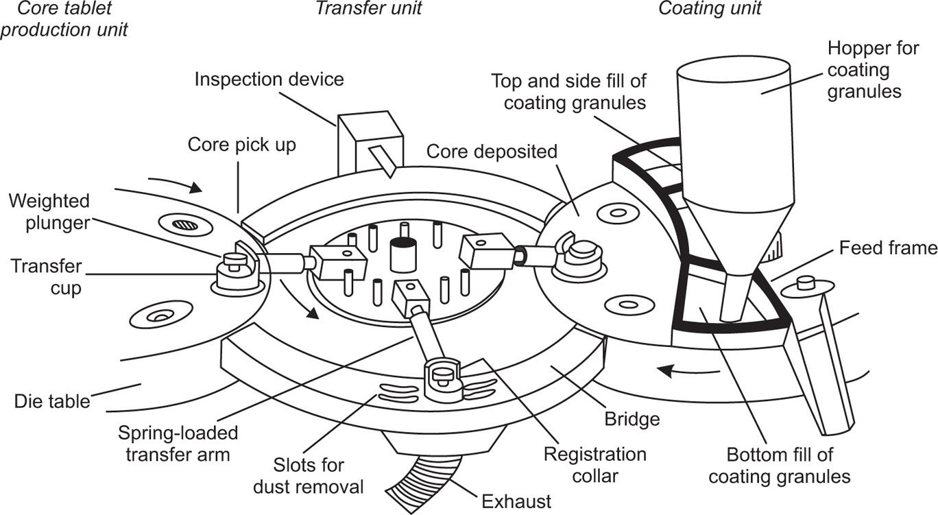
Fig. 21.17 Essential features of transfer mechanism of a compression coating machine (for clarity, only the die tables of the core and coating units and three transfer arms are shown).
Requirements for Core Tablets and Coating Granules
Performance
The Quality Control of Tablets
Uniformity of Diameter
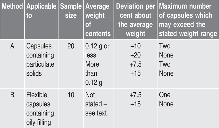
Tests for Uniformity of Weight and for Medicament Content
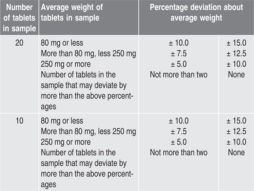
Test for Uniformity of Weight
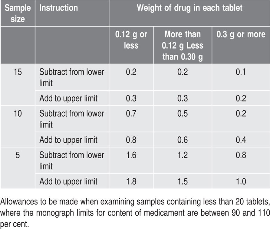
Content of Medicament
Test for Disintegration
Methods
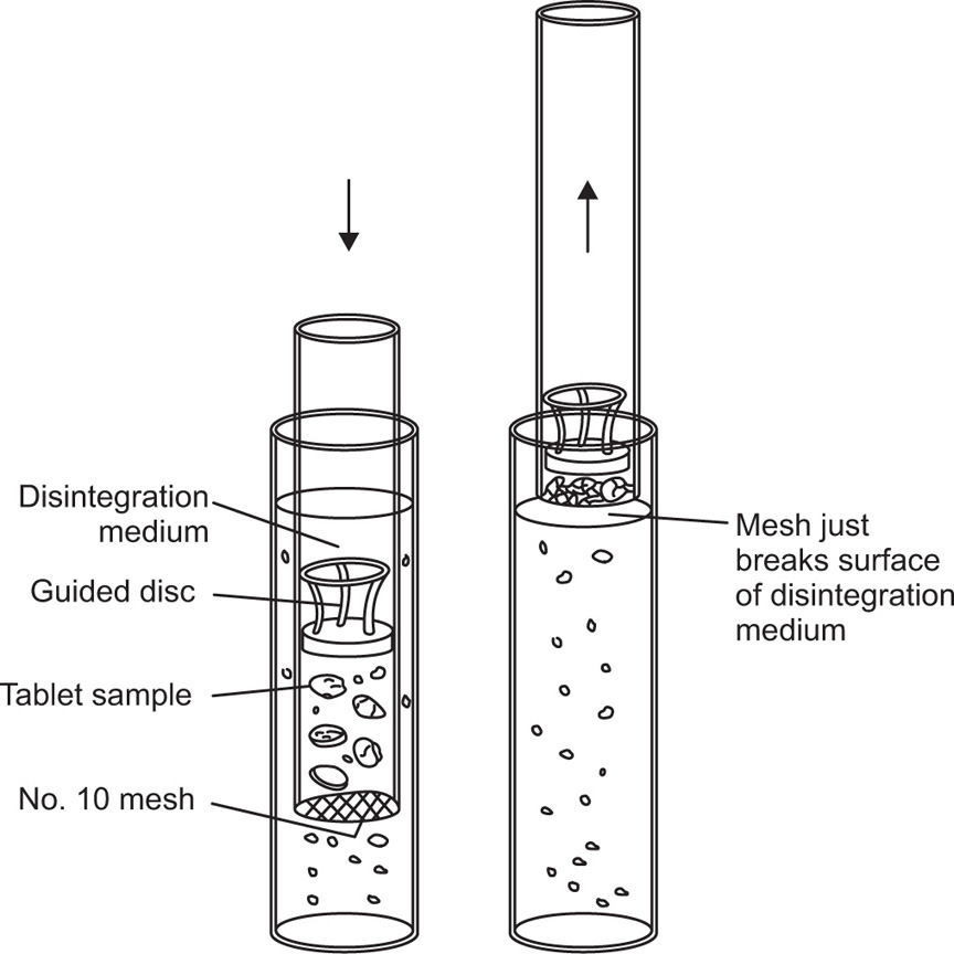
Fig. 21.18 Essential features of apparatus for the BP 1968 disintegration test showing guide disc in use.
Requirements
Comments on the Test
Colour
Hardness
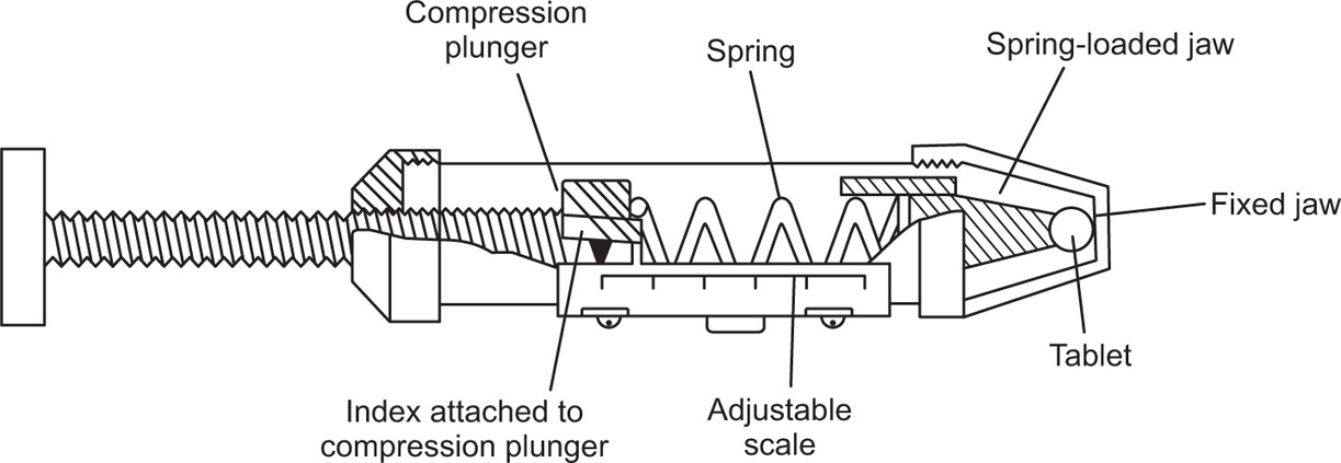
Fig. 21.19 The Monsanto tablet hardness tester.
Theoretical Studies in Tabletting Technology
The Compaction Process
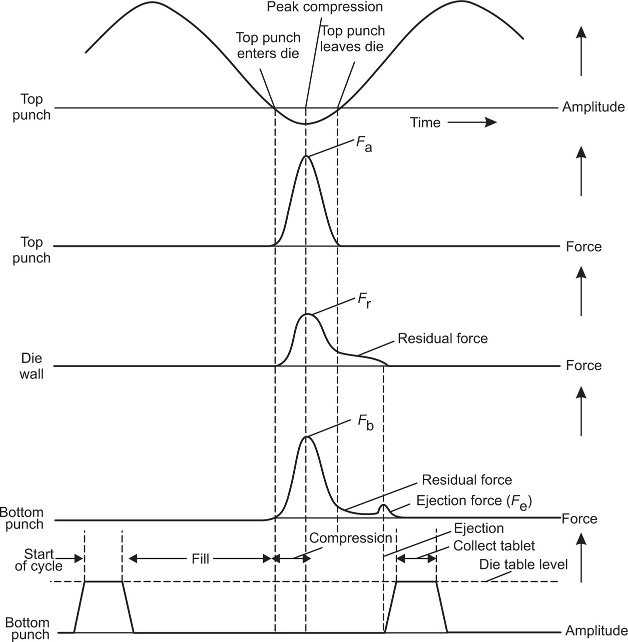
Fig. 21.20 Punch displacements and forces developed during tablet compression.
Table 21.9 Definitions of some parameters used in tabletting theory |
||
| Symbol | Definition | Derivation |
| A | Area of tablet in contact with die wall | πDL |
| Ap | Area of punch face | πD2/4 |
| D | Diameter of punch face | |
| Fa | Maximum upper punch force applied to compact | |
| Fb | Maximum force transmitted to lower punch by compact | |
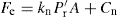
| Fc | Crushing force applied across a diameter to edges of compact, just sufficient to cause rupture | |
| Fd | Force lost to the die wall | Fa – Fb |
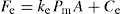
| Fe | Maximum force applied by lower punch to initiate ejection | |
| Fr | Maximum radial force at die wall during compaction | |
| Fr | Force normal to die wall during ejection | |
| kd | Die wall coefficient of friction during compaction | |
| ke | Die wall coefficient of friction during | |
| L | Observed length of compact | |
| L0 | Length compact would assume if compressed to zero porosity | W/Apρ0 |
| Pa | Maximum upper punch pressure | Fa/Ap |
| Pb | Maximum lower punch pressure | Fb/Ap |
| Pm | Mean compaction pressure | (Pa + Pb)/2 |
| Pr | Maximum radial pressure during compaction | Fr/A |
 |
Radial pressure during ejection of compact |  |
| R | Punch force ratio | Fb/Aa |
| T | Transmission ratio | Fb/A |
| V | Observed volume of tablet | Ap/La |
| V0 | Volume compact would assume if compressed to zero porosity | Pr/Pa |
| Vr | Relative volume of compact | Ap/La |
| W | Weight of tablet | W/ρ0 |
| ε | Porosity ratio of void to total volume | V/V0 |
| ρ | Observed density of compact | (V−V0)/V, 1 − ρr |
| ρ0 | True density of material used in compaction study | W/V |
| ρr | Relative density of tablet | ρ/ρ0, 1/Vr |
It is assumed that the punches are flat faced and circular in section. |
||
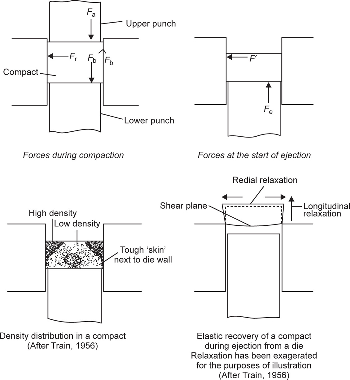
Fig. 21.21 Physical conditions during tabletting.
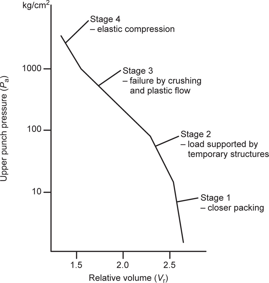
Fig. 21.22 Stages in the compaction of magnesium carbonate.
Tablet Hardness
Effect of Compaction Pressure
Effect of Materials Used and Tablet Dimensions
 (21.1)
Capping and Lamination
Granule Bonding and Relaxation Stresses
Residual Die-Wall Pressure
Hardness of Materials and Tablet Properties
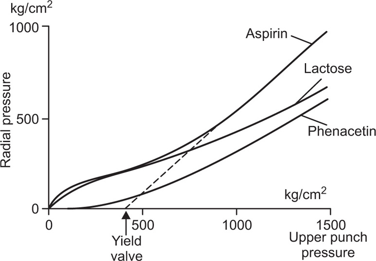
Fig. 21.23 Radial pressure as a function of upper punch pressure. after Windhesuer et al., 1963
Lubrication
Glidants
Die-wall Lubricants
 (21.2)
Table 21.13 Effect of lubricants on the disintegration time of sodium bicarbonate tablets compacted at approximately 1300kg/cm2 |
||
| Lubricant concentration per cent | Disintegration time (s) Stearic acid | Magnesium stearate |
| 0 | 200 | 200 |
| 0.25 | 370 | 1500 |
| 0.50 | 520 | 2000 |
| 0.75 | 680 | 2200 |
| 1.00 | 900 | 2300 |
| 2.00 | 1400 | 2900 |
| 4.00 | 2500 | 3800 |
 (21.3)
 , the radial force operating as ejection takes place, constitutes the normal load. As Fr = Pr A and
  , by analogy with Eq. 21.3:
 (21.4)
 (21.5)
 are proportional to a generalized compaction pressure (P) the appropriate substitution in Eqs. (21.4) and (21.5) yields expressions with a common factor (PA), which implies that Fe and Fd are linearly related. This has been confirmed by, for instance, Train (1956), Lewis and Shotton (1965a) and by other workers. Clearly, this is a simplification of a very complex process and could not be expected to apply directly to all materials and compaction conditions. Train’s data for the ejection of magnesium carbonate compacts was best represented by a power law, but Lewis and Shotton used linear expressions:
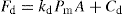 (21.6)
 (21.7)
 are determined by the transmission ratio (T) and this would not be identical for all lubricated substances which explains why these produced different values of Fd and Fe at a given mean compaction pressure.
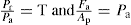
 (21.8)
 is proportional to Pa:
 (21.9)
Disintegration
Theory
 (21.10)
 (21.11)
 (21.12)
 (21.13)
 (21.14)
Effect of Granule Properties
Effects of Die-Wall Lubricants
Mode of Disintegrant Action
Capsules
Soft Capsules
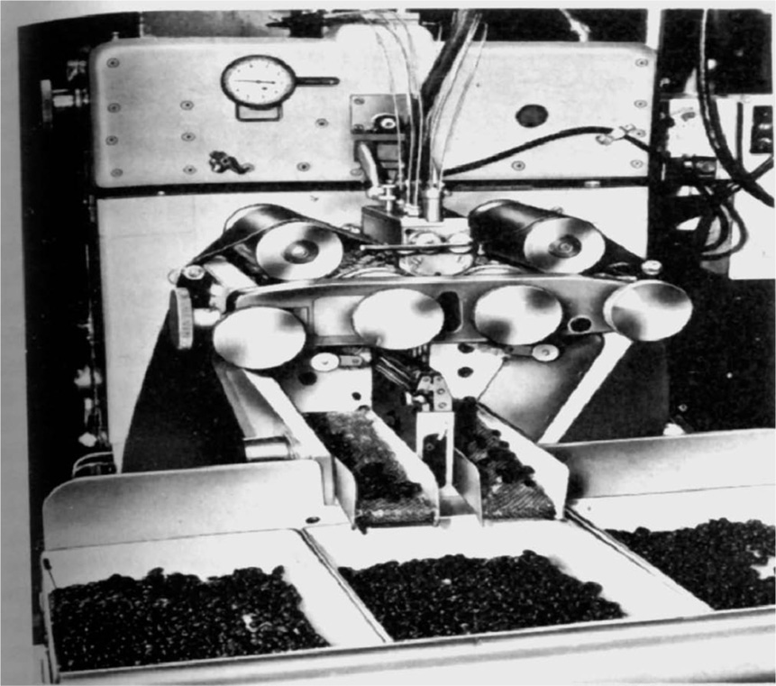
Fig. 21.24 The rotary die soft capsule filling machine. R.P. Scherer Ltd.
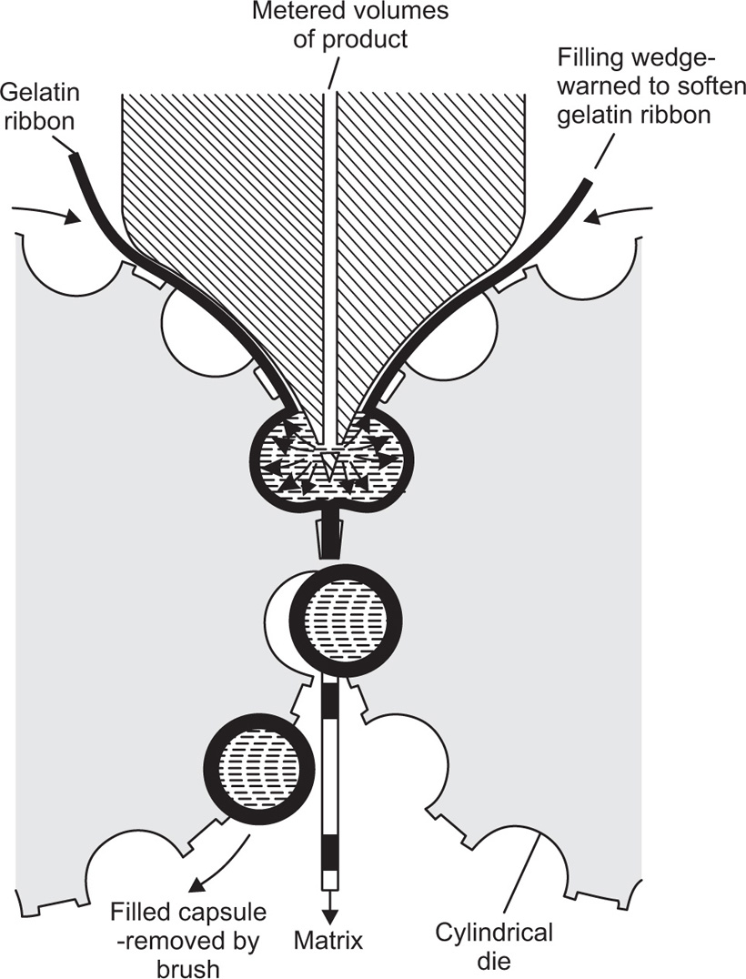
Fig. 21.25 Method of filling and sealing soft gelatin capsules in a rotary die machine (diagrammatic).
Hard Capsules
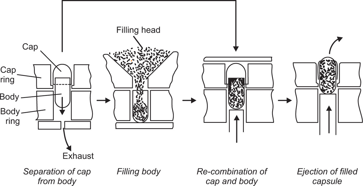
Fig. 21.26 Stages in the filling of hard capsules.
Quality Control of Capsules
Disintegration
Uniformity of Filling Weight