13 PATIENTS IN THE INTENSIVE THERAPY UNIT
In this chapter we concentrate on some of the pitfalls and difficulties that can occur when evaluating the bedside CXR in the intensive therapy unit (ITU).
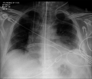
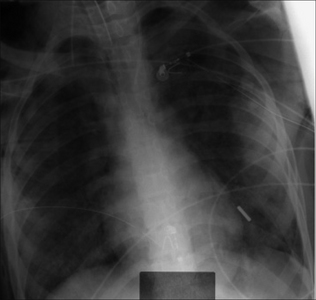
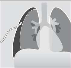
Figure 13.1 The CXR is essential for assesment of all lines, tubes and catheters. Careful analysis of the pulmonary and pleural appearances will assist clinical management.
THE BEDSIDE CXR
Misleading appearances may result from the patient’s position or be due to radiographic technique when a supine CXR is obtained.
LINES AND TUBES
These must be correctly positioned (Table 13.1). False readings, inadequate drainage and iatrogenic injury do occur.
| Line, tube, wire | Purpose/function | Best position for the tip |
|---|---|---|
| Central venous pressure line | Superior vena cava or brachiocephalic vein | |
| Swan–Ganz catheter (Pulmonary arterial catheter) | Main or lobar pulmonary artery | |
| Nasogastric tube | At least 10 cm beyond the gastro-oesophageal junction | |
| Nasoenteric tube | Beyond the gastric pylorus | |
| Intercostal drain (thoracostomy tube) | In the pleural space | |
| Endotracheal tube | 5–7 cm above the carina | |
| Tracheostomy tube | See p. 188. | |
| Junction of superior vena cava and right atrium | ||
| Mid oesophagus |
CENTRAL VENOUS PRESSURE (CVP) LINES
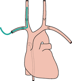
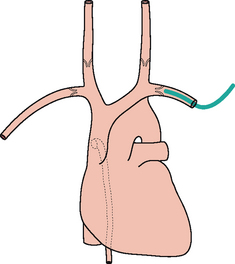
 Valves are present in the jugular and subclavian veins (Fig. 13.2). The tipof the central line must be distal to the valves otherwise central venous(i.e. right atrial) pressure readings will be inaccurate2,3. Rule of thumb: On the CXR, the superior vena cava (SVC) commences at the level of the right first anterior intercostal space. A curve at the tip of a CVP line suggests that the catheter is misplaced. Either it has entered a side vessel (Fig. 13.7), or it is jammed against the vessel wall, or it lies outside the vein.
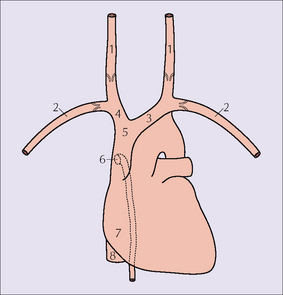
Figure 13.2 Vessels: 1 = internal jugular vein; 2 = subclavian vein; 3 = left brachiocephalic vein; 4 = right brachiocephalic vein;5 = SVC; 6 = orifice of the azygos vein;7 = right atrium;8 = inferior vena cava.
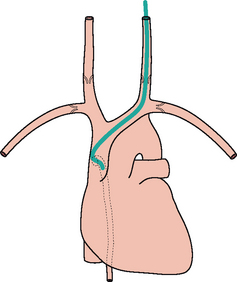
Figure 13.7 The tip of the internal jugular line is curved (kinked). A curve at the tip always suggests that it has entered a side vessel, or that it is jammed against the vessel wall, or that it has penetrated the wall and entered the soft tissues. In this example the tip has entered the azygos vein.
VALVES2
The last valve in the subclavian vein is 2 cm proximal to its junction with the internal jugular vein.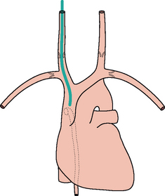
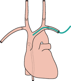
Figure 13.4 The tip of the left subclavian line is correctly positioned (i.e. well beyond the last valve in the vein).
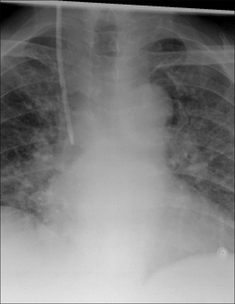
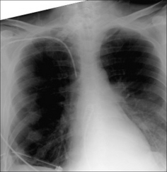
Figure 13.6 Right subclavian line in good position with its tip in the SVC. The SVC commences at the level of the right first anterior intercostal space. (Retouched.)
SWAN–GANZ (SG) CATHETER
A SG catheter (pulmonary arterial line) measures the pulmonary capillary wedge pressure. This allows an assessment of the left atrial pressure and cardiac output. These pressure measurements have been regarded as crucial in complex ITU cases and help to distinguish between cardiac and non-cardiac pulmonary oedema. However, the usefulness of these catheters has been disputed and some studies suggest that pulmonary artery catheters do not improve patient outcome4–7.
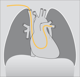
Figure 13.12 The tip of the SG catheter is correctly positioned; i.e. the tip does not project more than2 cm beyond the mediastinal outline.
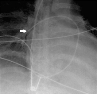
Figure 13.13 SG catheter. Correct position. The tip (arrow) of the catheter overlies the border of the heart.
Optimum position. The SG tip should be situated between the main pulmonary artery and the interlobar arteries. Apply this rule: on the CXR the SG tip should extend no more than 2.0 cm beyond the mediastinal shadow.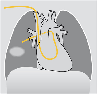
NASOGASTRIC (NG) TUBE
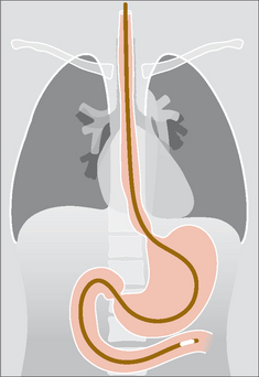
The NG tip must be at least 10 cm beyond the oesophago-gastric junction…this will ensure that a side hole (Fig. 13.16) is not situated in the intra-abdominal portion of the oesophagus (Figs 13.17 and 13.18).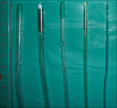
Figure 13.16 A selection of large bore and small bore NG tubes. Note the positions of the side holes which extend along the distal 5–10 cm of the tubes.
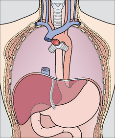
Figure 13.17 Part of the oesophagus is normally situated just below the diaphragm. It is important that the tip of a NG tube is positioned 10 cm or more below the gastro-oesophageal junction—otherwise some of the side holes are likely to be within the oesophageal lumen.
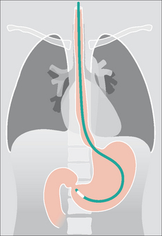
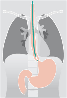
Figure 13.19 Unsatisfactory position. The tip of the NG tube is positioned below the diaphragm—but it is still within the oesophagus.
NASOENTERIC TUBE8
These feeding tubes are thin plastic catheters with a mercury/tungsten filled tip. The optimum position for the tip is distal to the pyloric sphincter.
Caution: because the tube is thin and flexible it can coil in the pharynx, oesophagus, or stomach. It may enter the trachea or the right main bronchus.
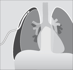
PLEURAL DRAINAGE TUBES3,8,9
The various appearances and diagnostic problems associated with pneumothoraces and pleural effusions are addressed on pp. 82–106. Important aspects relating to pleural drainage are described on pp. 100–101.
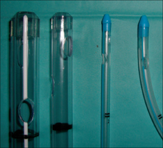
Figure 13.23 A selection of intercostal and pleural drainage tubes. Note the number and position of the side holes. Most tubes have at least two side holes.
ENDOTRACHEAL TUBE (ETT)3,8-14
Rule of thumb: The tip of an ETT will be in a satisfactory position if it approximates to the level of the medial ends of the clavicles…i.e. approximately 5–7 cm above an adult’s carina when the head is held in the neutral position.Identify the carina
If it is not visible—apply this rule of thumb: In 95% of people the carina is situated at the level of the T5–T7 thoracic vertebrae.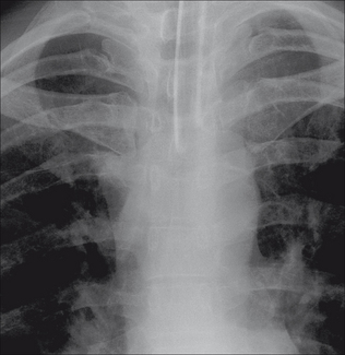
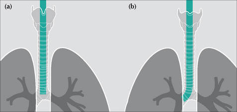
Figure 13.28 ETTs. Faulty positions. (a) Tip at level of the carina—i.e. much too low. Flexing the neck from the neutral position can cause the tip of an ETT to descend 1.9 cm down the airway. (b) The tip of this ETT has entered the right main bronchus. Because of the obliquity of the angle of origin of the right main bronchus a much-too-low ETT will usually enter the right main bronchus rather than the left main bronchus.
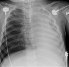
Figure 13.29 ETT. Faulty position. The ETT has entered the right main bronchus. The left lung is no longer aerated. As a consequence, there is extensive collapse of the left lung.
| ETT malposition 1 | ETT malposition 2 |
|---|---|
| Tip in the right main bronchus. May cause: | Tube in the oesophagus. CXR evidence: |
TRACHEOSTOMY TUBE
On a CXR the side walls of the tracheostomy tube should lie parallel to the outer margins of the trachea (Fig. 13.30).
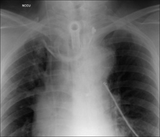
Figure 13.30 Tracheostomy tube. Good position. Note that the walls of the tracheostomy tube parallel the walls of the trachea.
Table 13.3 The CXR following introduction of a tracheostomy tube.
| Normal | Abnormal |
|---|---|
DOPPLER ULTRASOUND PROBE
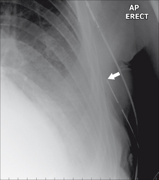
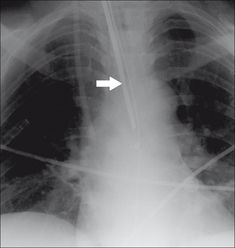
An oesophageal probe is a minimally invasive instrument for monitoring cardiac output (via measurement of blood flow velocity in the descending aorta). Optimum probe position is at the level (approximately) of the mid oesophagus. Of course it is the clear ultrasound signal that confirms that probe position is good. Nevertheless, the doppler probe shadow (Fig. 13.31) should be familiar to those who evaluate ITU CXRs.
THE LUNGS IN ITU
CONSOLIDATION, COLLAPSE, INFARCTION
The ITU patient is at risk of developing pneumonia, lobar collapse due to obstructive secretions, pleural effusion and pulmonary infarction. The relevant CXR appearances are described elsewhere:
COMPLICATIONS OF MECHANICAL VENTILATION
Pneumothorax is common in ITU patients. It is usually consequent on mechanical ventilation. Sometimes it is a complication of subclavian artery line insertion. Detecting a pneumothorax on a supine CXR can be very challenging. The features to look for have been described earlier (pp. 97–106).
DIFFUSE LUNG PATHOLOGY11,12,15-17
The CXR:
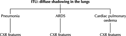
 Frequently it is clinically—and radiologically—difficult to tell whether diffuse shadows are due to pneumonia, adult respiratory distress syndrome (ARDS), pulmonary oedema…or a combination of these. Table 13.4 provides some CXR features that can be helpful. But we must emphasise that assigning a specific pathological process to the shadows can be problematic. Indeed, extensive shadowing on a CXR often represents a combination of pneumonia, areas of lung collapse, pleural fluid, and ARDS. ARDS:
ARDS is a common cause for diffuse changes in the lungs. It results from an acute alveolar insult causing pulmonary inflammation and small vessel injury. The damaged endothelium leaks fluid and protein into the alveoli. There are numerous causes for ARDS including trauma, shock, systemic infection, head injury, multiple blood transfusions, severe pneumonia, smoke inhalation.
Frequently it is clinically—and radiologically—difficult to tell whether diffuse shadows are due to pneumonia, adult respiratory distress syndrome (ARDS), pulmonary oedema…or a combination of these. Table 13.4 provides some CXR features that can be helpful. But we must emphasise that assigning a specific pathological process to the shadows can be problematic. Indeed, extensive shadowing on a CXR often represents a combination of pneumonia, areas of lung collapse, pleural fluid, and ARDS. ARDS:
ARDS is a common cause for diffuse changes in the lungs. It results from an acute alveolar insult causing pulmonary inflammation and small vessel injury. The damaged endothelium leaks fluid and protein into the alveoli. There are numerous causes for ARDS including trauma, shock, systemic infection, head injury, multiple blood transfusions, severe pneumonia, smoke inhalation.Table 13.4 The CXR and diffuse lung shadows.
 |
||
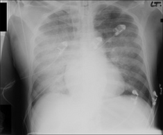
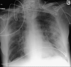
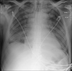
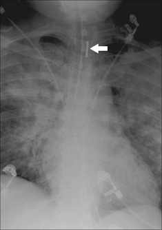
Figure 13.34 Pulmonary oedema secondary to intracranial haemorrhage. Bilateral airspace (alveolar) shadowing.
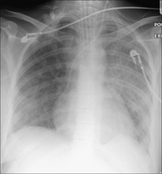
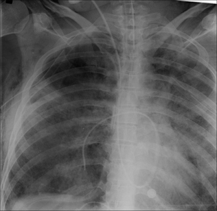
Figure 13.35 Extensive pneumonia in both lungs. This appearance is indistinguishable from the diffuse alveolar shadowing that occurs in ARDS. The clinical history and examination together with the bacteriological findings indicated that the lung changes were due to infection—not to ARDS.
Analyse the CXR carefully. In one series of over a thousand consecutive ITU CXRs 35% had clinically unsuspected abnormalities20. An intravenous catheter or pacing wire may adopt a seemingly bizarre—butclearly intravenous—route as shown on the CXR. Several possibilities. It mayhave fortuitously entered a small but normal vein, e.g. the internal thoracic(i.e. mammary) vein. Alternatively, the patient may have a venous anomaly(e.g. a persistent left SVC). Thoracic venous anatomy—normal and anomalous—has been elegantly described by Godwin and Chen2. Pleural drainage tubes—position21:
1. Zylak CJ, Littleton JT, Dinizch ML. Illusory consolidation of the left lower lobe: a pitfall of portable radiography. Radiology. 1988;167:653-655.
2. Godwin JD, Chen JTT. Thoracic venous anatomy. AJR. 1986;147:674-684.
3. Dunbar RD. Radiologic Appearance of compromised thoracic catheters, tubes, and wires. Radiol Clin North Am. 1984;22:699-722.
4. Binanay C, Califf RM, Hasselblad V, et al. Evaluation study of congestive heart failure and pulmonary artery catheterization effectiveness: the ESCAPE trial. JAMA. 2005;294:1625-1633.
5. National Heart, Lung, and Blood Institute Acute Respiratory Distress Syndrome (ARDS) Clinical Trials Network. Pulmonary-artery versus central venous catheter to guide treatment of acute lung injury. N Engl J Med. 2006;354:2213-2224.
6. Shure D. Pulmonary-artery catheters — peace at last? N Engl J Med. 2006;354:2273.
7. Finfer S, DeLaney A. Pulmonary artery catheters. BMJ. 2006;333:930-931.
8. Aronchick JM, Miller WT. Tubes and lines in the intensive care setting. Semin Roentgenol. 1997;32:102-116.
9. Wechsler RJ, Steiner RM, Kinori I. Monitoring the monitors: the radiology of thoracic catheters, wires, and tubes. Semin Roentgenol. 1988;23:61-84.
10. Conrardy P, Goodman L, Lainge F, et al. Alteration of endotracheal tube position (flexion and extension of the neck). Crit Care Med. 1976;4:8-12.
11. Goodman LR, Putman CE. Radiological evaluation of patients receiving assisted ventilation. JAMA. 1981;245:858-860.
12. Sanders C. Chest radiography in the intensive care unit: pitfalls and potential. Current Imaging. 1989;1:147-153.
13. Smith GM, Reed JC, Choplin RH. Radiographic detection of esophageal malpositioning of endotracheal tubes. AJR. 1990;154:23-26.
14. Rollins RJ, Tocino I. Early radiographic signs of tracheal rupture. AJR. 1987;148:695-698.
15. Greene R. Adult respiratory distress syndrome: acute alveolar damage. Radiology. 1987;163:57-66.
16. Greene R, Jantsch H, Boggis C, et al. Respiratory distress syndrome with new considerations. Radiol Clin North Am. 1983;21:699-708.
17. Milne ENC, Pistolesi M, Miniati M, et al. The radiologic distinction of cardiogenic and non-cardiogenic edema. AJR. 1985;144:879-894.
18. Miller KS, Sahn SA. Chest tubes. Indications, technique, management and complications. Chest. 1987;91:258-264.
19. Cameron EW, Mirvis SE, Shanmuganathan K, et al. Computed tomography of malpositioned thoracostomy drains: a pictorial essay. Clin Radiol. 1997;52:187-193.
20. Bekemeyer WB, Crapo RO, Calhoun S, et al. Efficacy of chest radiography in a respiratory intensive care unit. Chest. 1985;88:691-696.
21. Curtin JJ, Goodman LR, Quetteman EJ, et al. Thoracostomy tubes after acute chest injury: relationship between location in a pleural fissure and function. AJR. 1994;163:1339-1342.
22. Duponselle EFC. The level of the intercostal drain and other determining factors in the conservative approach to penetrating chest injuries. Afr J Med. 1980;26:52-55.
23. Hegarty MM. A conservative approach to penetrating injuries of the chest: experience with 131 successive cases. Injury. 1976;8:53-59.
24. Webb WR, La Berge JM. Radiographic recognition of chest tube malposition in the major fissure. Chest. 1984;85:81-83.