1 CHEST RADIOLOGY: THE BASIC BASICS
You will need a basic understanding of some of the technical factors affecting chest radiography, if only to recognise when a particular appearance arises not from pathology but from suboptimal technique. This chapter concentrates on the frontal CXR. We discuss the lateral CXR in Chapter 2.
THE RADIOGRAPHIC IMAGE
Table 1.1 Attenuation of the x-ray beam.
| Tissue absorption | Effect on the radiograph (see Fig. 1.1) | |
|---|---|---|
| Least | Air or gas | Black image |
 |
Fat | Dark grey image |
| Soft tissue | Grey image | |
| Most | Bone or calcium | White image |
THE FRONTAL CXR
This standard CXR is obtained at a fixed distance between the x-ray tube and the cassette of 180 cm (6 ft). The patient faces the cassette and the x-ray beam passes through in the posterior to anterior direction, i.e. PA (Fig. 1.2).
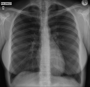
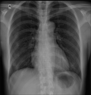
Figure 1.1 Normal PA CXR. Standard radiographic technique allows comparison of the heart size on any previous or subsequent PA CXR.
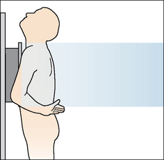
Figure 1.2 Patient positioning for a standard PA CXR. The 180 cm (6 ft) x-ray tube to cassette distance results in a beam that is minimally divergent. In effect, the x-rays are parallel when they impact on the thorax.
The PA CXR is preferred because the radiographic technique is standard. This allows accurate and valid comparison between repeated PA CXRs.
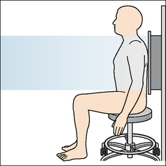
If the patient is unable to stand erect then he faces the x-ray tube and an antero–posterior (AP) chest radiograph is obtained. AP CXRs are acquired:
 At the bedside or with a seriously ill or frail patient in the emergency department. The patient may be lying supine (Fig. 1.3) or sitting up. In the radiology department when the patient is either too frail or too unsteady to stand erect. The radiographer (technologist) sits the patient ona chair with his back to the cassette (Fig. 1.4).
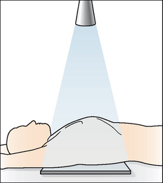
Figure 1.3 Bedside (i.e. portable) radiograph, patient supine. AP CXR. The distance from the x-ray source to the cassette is much less than 180 cm (6 ft).
THE BEDSIDE (PORTABLE) AP CXR HAS DISADVANTAGES
The AP CXR should always be interpreted with caution (Fig. 1.5). The following factors may cause misleading appearances:
When lying supine a patient is often unable to take a full inspiration. Also, he may be rotated because of difficulty in cooperating. Therefore some AP CXRs are of inferior quality in comparison with a departmental PA radiograph.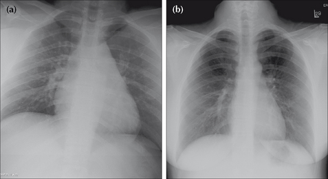
Figure 1.5 Age 24. (a) AP CXR. Is the heart enlarged? It looks big but it is difficult to be sure because the radiographic technique produces magnification of the cardiac shadow. (b) PA CXR one day later. The CXR is entirely within normal limits.
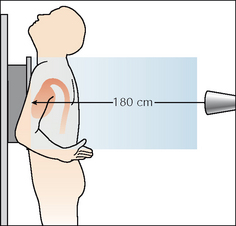
Figure 1.6 On a PA CXR the heart is situated anteriorly in relation to the cassette. The 180 cm distance means that there is minimal divergence of the x-ray beam. Cardiac magnification is limited.
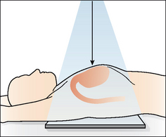
Figure 1.7 On a bedside (portable) AP CXR the heart is situated well away from the cassette. The x-ray beam diverges at the margins of the heart causing magnification. A second cause for magnification is the shorter distance from the x-ray tube to the cassette. This is invariably less than 180 cm and produces a divergent x-ray beam.
Be careful of making a major diagnosis (e.g. hilar mass) too readily. But don’t be too gloomy. Many AP radiographs, even if not meeting the quality expected of a PA CXR, will usually confirm whether or not the lungs are clear.
MAGNIFICATION ON AN AP CXR: DOES IT MATTER?
Magnification occurs because of two factors:
The drawbacks of magnification are:
Precise comparison of the mediastinal appearance with an earlier or subsequent PA radiograph is a risky business.| Demonstration: | A coin is taped to the front of a chest (phantom) and another coin is taped to the back. An AP CXR is obtained. |
| CXR result: | The coin on the back of the phantom (close to the cassette) appears of near normal size. The coin on the front of the phantom (further away from the cassette) appears much larger. |
DEPTH OF INSPIRATION: DOES IT MATTER?
Rule of thumb: If the anterior aspects of at least six ribs do not lie above the left dome of the diaphragm, then suspect a shallow inspiration (see Chapter 16, p. 237).
Shallow inspiration is common in the elderly, those in pain, unconscious patients, and with bedside radiography. Two problems occur when an inspiration is shallow:
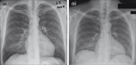
Figure 1.8 PA CXRs of the same patient taken minutes apart: (a) was obtained during a good inspiration, and (b) was obtained during a poor inspiration. In (b) the heart appears enlarged…but this is bogus. A shallow inspiration can cause spurious cardiomegaly and also crowding of vessels at the lung bases. The latter appearance can mimic infection.
PATIENT ROTATION: DOES IT MATTER?
Rule of thumb: The patient is not rotated if a vertical line drawn through the centre of the vertebral bodies (T1–T5) is equidistant from the medial end of each clavicle. Rotation is present when one of the clavicles is further away from this vertical line (Fig. 1.9).
A rotated CXR will cause various structures to be projected towards the right or left side. Potential problems:
Rotation to the right on a PA CXR…the manubrium and/or superior vena cava and/or vessels arising from the arch of the aorta may become unusually prominent on the right. This can simulate a mediastinal mass. Rotation to the left on an AP CXR…the aortic arch may appear enlarged. Rotation is a common cause for one lung appearing blacker than the opposite side (see p. 257).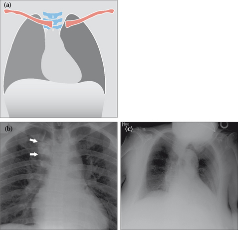
Figure 1.9 Patient rotation. (a) Rotation to the left.(b) Male. Age 43. AP CXR. Rotation to the right projects the manubrium and aortic arch vessels (arrows) over the right upper zone, mimicking a mass.(c) Female. Age 87. Rotation to the left makes the aortic arch appear unduly prominent.
Rotation is often a problem in drowsy or ill adults, and in little children who wriggle around and do not like being held still.
OVEREXPOSURE/UNDEREXPOSURE—BE CAREFUL
With analogue chest radiography a poor exposure (film too dark or film too pale) can lead to errors in diagnosis because some areas or structures cannot be seen. With digital imaging the ability to alter (i.e. window) the image electronically will often help to overcome these problems.
SCAPULA POSITION—BE CAREFUL
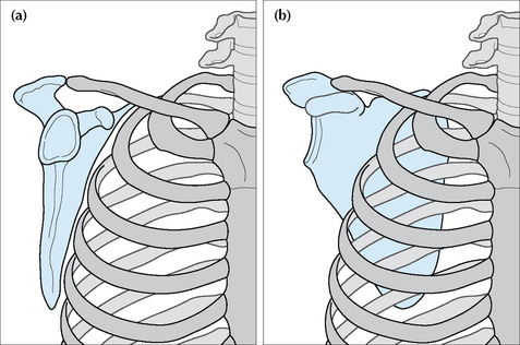
The frontal CXR should have the scapulae rotated off the thorax and projected well away from the lungs (Fig. 1.10). This is not always easy to achieve in elderly, frail or sick people. Misleading shadows (e.g. a spurious pneumothorax) can be produced when part of a scapula overlies a lung.
OCCASIONAL PITFALL—BEDSIDE RADIOGRAPHS AND BEAMANGULATION ARTEFACT
Rule of thumb: On PA and AP CXRs both domes of the diaphragm should be well-defined. If either dome is obliterated—in part or in whole—then disease in the adjacent lower lobe is highly likely (pp. 46–47). This rule is an application of the silhouette sign (Chapter 4, pp. 42–51).
With bedside radiographs this rule of thumb still applies, but with a caveat. On occasion the x-ray beam may not be perpendicular to the patient’s chest, but may be angled upwards. Angulation can cause the left dome of the diaphragm to be ill-defined1,2. So, if the left dome is ill-defined on a bedside CXR and this is unexpected or does not fit with the findings on clinical examination, then the CXR should be repeated ensuring that the beam is perpendicular to the thorax. Alternatively, obtain a lateral CXR and check the appearance of the left lower lobe.
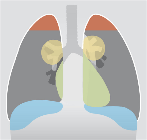
WHAT ARE THE LUNG ZONES?
It is common practice to define areas of the lung on the frontal CXR in terms of “zones”. The purpose is to describe approximately where lesions are situated. Some experts attempt to define these zones very precisely by reference to specific ribs. Others are much more pragmatic, using the terms “upper”, “mid” and “lower” zones informally, without feigning pseudo-scientific precision. We follow the latter course.
READING THE FRONTAL CXR
Many different schemes have been proposed for reading CXRs. There is no single correct or best system. In general it does not matter what your system is provided that you:
THE FRONTAL CXR: A TEN-POINT CHECKLIST
 If the anterior end of the left sixth rib reaches or is projected above the level of the dome of the diaphragm—then a good inspiration is likely. Pitfall. A small inspiration can cause: (a) the heart to appear enlarged; and (b) vessel crowding at the bases mimicking infection (Fig. 1.12). The medial end of each clavicle should be equidistant from a vertical line drawn through the spinous processes of the T1–T5 vertebral bodies. Pitfalls. Rotation can distort the mediastinal and hilar appearances and lead to the erroneous suggestion of a mediastinal or hilar mass. One lung may appear blacker than the other (see p. 257). Always interpret rotated films with caution. In an adult, the cardio-thoracic ratio (CTR) should be less than 50% on a PA radiograph (see p. 148). Rule of thumb: The left hilum should be at the same level or higher than the right…never lower than the right (Fig. 1.15).
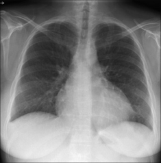
Figure 1.11 The heart appears enlarged in this 25-year-old female…but this is an AP CXR. Magnification factors can mislead the unwary.
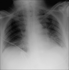
Figure 1.12 Patient in ITU. Age 70. Shadowing at the bases suggests infection…but this is a poor inspiration. Crowding of vessels at the lung bases results from the inadequate inspiration.
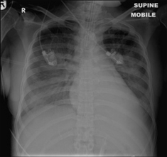
Figure 1.13 ITU. Patient has adult respiratory distress syndrome (ARDS) and clinical deterioration. The normal, well-defined margin of the left dome of the diaphragm is absent…because of pneumonia in the adjacent left lower lobe.
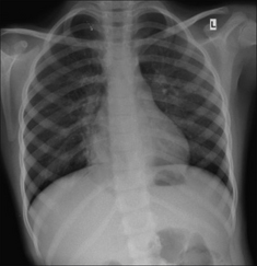
Figure 1.14 Patient with cough and fever. The normal, sharply defined right heart border is lost…because of pneumonia in the adjacent middle lobe.
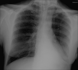
Figure 1.15 Checking the hila. In this patient the left hilum has disappeared because there is collapse of the left lower lobe. (Hilar appearances, both normal and abnormal, are described in Chapter 6, pp. 70–79.)