CHAPTER 31 Radiographic Aids in the Diagnosis of Periodontal Disease
Radiographs are valuable for diagnosis of periodontal disease, estimation of severity, determination of prognosis, and evaluation of treatment outcome. However, radiographs are an adjunct to the clinical examination, not a substitute for it.
Radiographs demonstrate changes in calcified tissue; they do not reveal current cellular activity but rather reflect the effects of past cellular experience on the bone and roots.
Normal Interdental Bone
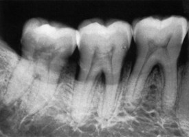
Evaluation of bone changes in periodontal disease is based mainly on the appearance of the interdental bone because the relatively dense root structure obscures the facial and lingual bony plates. The interdental bone normally is outlined by a thin, radiopaque line adjacent to the periodontal ligament (PDL) and at the alveolar crest, referred to as the lamina dura (Figure 31-1). Because the lamina dura represents the cortical bone lining the tooth socket, the shape and position of the root and changes in the angulation of the x-ray beam produce considerable variations in its appearance.15
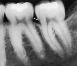
Figure 31-1 Crest of interdental bone normally parallel to a line drawn between the cementoenamel junction of adjacent teeth (arrow). Note also the radiopaque lamina dura around the roots and interdental bone.
The width and shape of the interdental bone and the angle of the crest normally vary according to the convexity of the proximal tooth surfaces and the level of the cementoenamel junction (CEJ) of the approximating teeth.29 The faciolingual diameter of the bone is related to the width of the proximal root surface. The angulation of the crest of the interdental septum is generally parallel to a line between the CEJs of the approximating teeth (see Figure 31-1). When there is a difference in the level of the CEJs, the crest of the interdental bone appears angulated rather than horizontal.
Radiographic Techniques
In conventional radiographs, periapical and bite-wing projections offer the most diagnostic information and are most commonly used in the evaluation of periodontal disease. To properly and accurately depict periodontal bone status, proper techniques of exposure and development are required. The bone level, pattern of bone destruction, PDL space width,33 as well as the radiodensity, trabecular pattern, and marginal contour of the interdental bone, vary by modifying exposure and development time, type of film, and x-ray angulation.17 Standardized, reproducible techniques are required to obtain reliable radiographs for pretreatment and posttreatment comparisons.16,24,31
Prichard23 established the following four criteria to determine adequate angulation of periapical radiographs:
For periapical radiographs, the long-cone paralleling technique most accurately projects the alveolar bone level8 (Figure 31-2). The bisection-of-the-angle technique elongates the projected image, making the bone margin appear closer to the crown; the level of the facial bone is distorted more than that of the lingual. Inappropriate horizontal angulation results in tooth overlap, changes the shape of the interdental bone image, alters the radiographic width of the PDL space and the appearance of the lamina dura, and may distort the extent of furcation involvement (see Figure 31-2).19
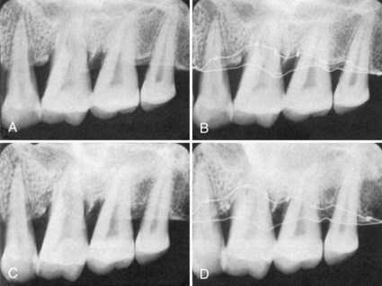
Figure 31-2 Comparison of long-cone paralleling and bisection-of-the-angle techniques. A, Long-cone paralleling technique, radiograph of dried specimen. B, Long-cone paralleling technique, same specimen as A. Smooth wire is on margin of the facial plate and knotted wire is on the lingual plate to show their relative positions. C, Bisection-of-the-angle technique, same specimen as A and B. D, Bisection-of-the-angle technique, same specimen. Both bone margins are shifted toward the crown, the facial margin (smooth wire) more than the lingual margin (knotted wire), creating the illusion that the lingual bone margin has shifted apically.
(Courtesy Dr. Benjamin Patur, Hartford, CT.)
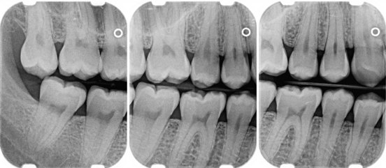
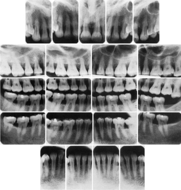
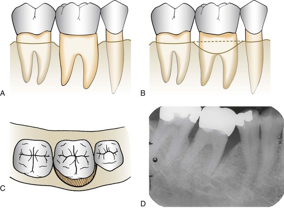
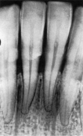
Periapical radiographs frequently do not reveal the correct relationship between the alveolar bone and the CEJ. This is particularly true in cases in which a shallow palate or floor of the mouth does not allow ideal placement of the periapical film. Bite-wing projections offer an alternative that better images periodontal bone levels. For bite-wing radiographs, the film is placed behind the crowns of the upper and lower teeth parallel to the long axis of the teeth. The x-ray beam is directed through the contact areas of the teeth and perpendicular to the film.35 Thus the projection geometry of the bite-wing films allows the evaluation of the relationship between the interproximal alveolar crest and the CEJ without distortion (Figures 31-3 and 31-4). If the periodontal bone loss is severe and the bone level cannot be visualized on regular bite-wing radiographs, films can be placed vertically to cover a larger area of the jaws (Figure 31-5). More than two vertical bite-wing films might be necessary to cover all the interproximal spaces of the area of interest.
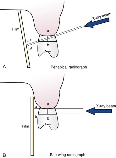
Figure 31-3 Schematic diagram of periapical (A) and bite-wing (B) radiographs. Angulation of the x-ray beam and the film on the periapical radiograph distort the distance between the alveolar crest and the cementoenamel junction (CEJ) (compare a-b versus a1-b1). In contrast, the projection geometry of the bite-wing radiograph allows a more accurate depiction (a2-b2) of the distance between the alveolar crest and the CEJ (a-b).
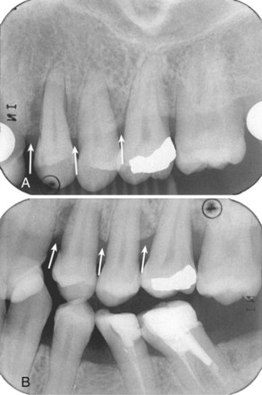
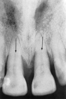
Figure 31-4 Periapical (A) and bite-wing (B) radiographs from full-mouth series of patient with periodontitis. The periapical film clearly underestimates the amount of bone loss (white arrows). Because of appropriate projection geometry, the alveolar crest height is accurately depicted on the bite-wing radiograph (white arrows).
Bone Destruction In Periodontal Disease
Early destructive changes of bone that do not remove sufficient mineralized tissue cannot be captured on radiographs.3,4,25 Therefore slight radiographic changes of the periodontal tissues suggest that the disease has progressed beyond its earliest stages. The earliest signs of periodontal disease must be detected clinically.
Bone Loss
The radiographic image tends to underestimate the severity of bone loss.28,32 The difference between the alveolar crest height and the radiographic appearance ranges from 0 mm to 1.6 mm,27 mostly accounted for by x-ray angulation.
Amount
Radiographs are an indirect method for determining the amount of bone loss in periodontal disease; they image the amount of remaining bone rather than the amount lost. The amount of bone lost is estimated to be the difference between the physiologic bone level and the height of the remaining bone.
The distance from the CEJ to the alveolar crest has been analyzed by several investigators.12,14,27 Most studies, conducted in adolescents, suggest a distance of 2 mm to reflect normal periodontium; this distance may be greater in older patients.
Pattern of Bone Destruction
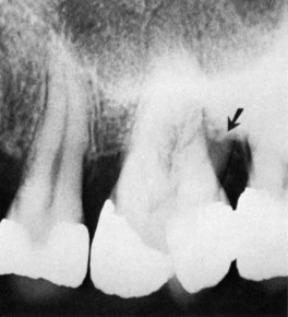
In periodontal disease the interdental bone undergoes changes that affect the lamina dura, crestal radiodensity, size and shape of the medullary spaces, and height and contour of the bone. Height of interdental bone may be reduced, with the crest perpendicular to the long axis of the adjacent teeth (horizontal bone loss; Figure 31-6), or angular or arcuate defects (angular, or vertical, bone loss; Figure 31-7) could form (see Chapter 14).
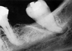
Radiographs do not indicate the internal morphology or depth of craterlike defects. Also, radiographs do not reveal the extent of involvement on the facial and lingual surfaces. Bone destruction of facial and lingual surfaces is masked by the dense root structure, and bone destruction on the mesial and distal root surfaces may be partially hidden by superimposed anatomy, such as a dense mylohyoid ridge (Figure 31-8). In most cases, it can be assumed that bone losses seen interdentally continue in either the facial or the lingual aspect, creating a troughlike lesion.
Dense cortical facial and lingual plates of interdental bone obscure destruction of the intervening cancellous bone. Thus a deep craterlike defect between the facial and lingual plates might not be depicted on conventional radiographs. To record destruction of the interproximal cancellous bone radiographically, the cortical bone must be involved. A reduction of only 0.5 to 1.0 mm in the thickness of the cortical plate is sufficient to permit radiographic visualization of destruction of the inner cancellous trabeculae.20
Interdental bone loss may continue facially and/or lingually to form a troughlike defect that could be difficult to appreciate radiographically. These lesions may terminate on the radicular surface or may communicate with the adjacent interdental area to form one continuous lesion (Figure 31-9).
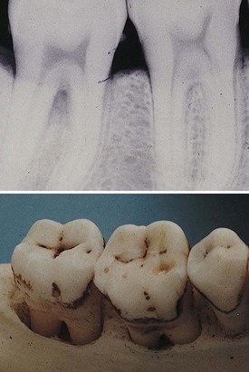
Figure 31-9 Interdental lesion that extends to the facial or lingual surfaces in a troughlike manner.
Figure 31-10 shows two adjacent interdental lesions connecting on the radicular surface to form one interconnecting osseous lesion. Along with clinical probing of these lesions, the use of a radiopaque pointer placed in these radicular defects will demonstrate the extent of the bone loss.
Radiographic Appearance of Periodontal Disease
Periodontitis
Radiographic changes in periodontitis follow the pathophysiology of periodontal tissue destruction and include the following:
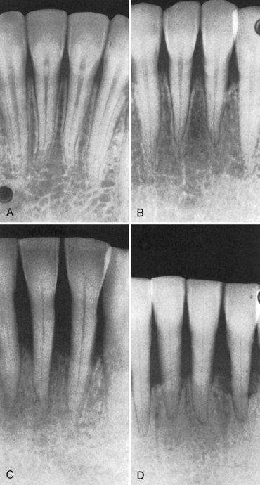
Figure 31-11 Radiographic changes in periodontitis. A, Normal appearance of interdental bone. B, Fuzziness and a break in the continuity of the lamina dura at the crest of the bone distal to the central incisor (left). There are wedge-shaped radiolucent areas at the crest of the other interdental bone. C, Radiolucent projections from the crest into the interdental bone indicate extension of destructive processes. D, Severe bone loss.
Interdental Craters
Interdental craters are seen as irregular areas of reduced density on the alveolar bone crests.28 Craters are generally not sharply demarcated but gradually blend with the rest of the bone. Conventional radiographs do not accurately depict the morphology or depth of interdental craters, which sometimes appear as vertical defects.
Furcation Involvement
Definitive diagnosis of furcation involvement is made by clinical examination, which includes careful probing with a specially designed probe (e.g., Nabers). Radiographs are helpful, but root superimposition, caused by anatomic variations and/or improper technique, can obscure radiographic representation of furcation involvement. As a general rule, bone loss is greater than it appears in the radiograph. A tooth may present marked bifurcation involvement in one film (Figure 31-12, A) but appear to be uninvolved in another (Figure 31-12, B). Radiographs should be taken at different angles to reduce the risk of missing furcation involvement.
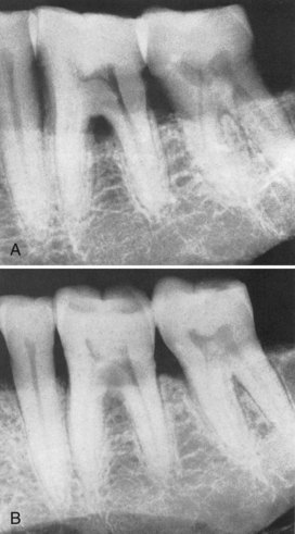
Figure 31-12 A, Furcation involvement indicated by triangular radiolucency in bifurcation area of mandibular first molar. The second molar presents only a slight thickening of the periodontal space in the bifurcation area. B, Same area as A, different angulation. The triangular radiolucency in the bifurcation of the first molar is obliterated, and involvement of the second molar bifurcation is apparent.
The recognition of a large, clearly defined radiolucency in the furcation area is easy to identify (see Figure 31-12, A), but less clearly defined radiographic changes are often overlooked. To assist in the radiographic detection of furcation involvement, the following diagnostic criteria are suggested:
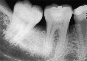
Figure 31-13 Early furcation involvement suggested by fuzziness in the bifurcation of the mandibular first molar, particularly when associated with bone loss on the roots.
Periodontal Abscess
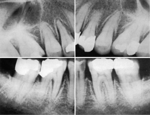
The typical radiographic appearance of the periodontal abscess is a discrete area of radiolucency along the lateral aspect of the root (Figures 31-16 and 31-17). However, the radiographic picture is often not characteristic (Figure 31-18). This can be due to the following:
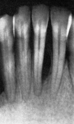
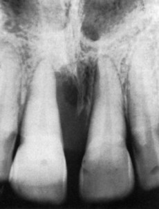
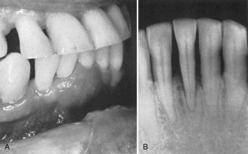
Figure 31-18 Chronic periodontal abscess. A, Periodontal abscess in the right central and lateral incisor area. B, Extensive bone destruction and thickening of the periodontal ligament space around the right central incisor.
Therefore radiographs alone cannot provide final diagnosis of a periodontal abscess but need to be accompanied by careful clinical examination.
Clinical Probing
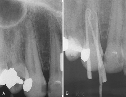
Regenerative and resective flap designs and incisions require prior knowledge of the underlying osseous topography. Careful probing of these pocket areas after scaling and root planing often require local anesthesia and definitive radiographic evaluation of the osseous lesions. Radiographs taken with periodontal probes or other indicators (e.g., Hirschfeld pointers) placed into the anesthetized pocket show the true extent of the bone lesion. As indicated previously, the attachment level on the radicular surface or interdental lesions with thick facial or lingual bone cannot be visualized in the radiograph. The use of radiopaque indicators is an efficient diagnostic aid (Figure 31-19).
Localized Aggressive Periodontitis
Localized aggressive (formerly “localized juvenile”) periodontitis is characterized by the following:
Trauma from Occlusion
Trauma from occlusion can produce radiographically detectable changes in the thickness of the lamina dura, morphology of the alveolar crest, width of the PDL space, and density of the surrounding cancellous bone.
Traumatic lesions manifest more clearly in faciolingual aspects because mesiodistally the tooth has the added stability provided by the contact areas with adjacent teeth. Therefore slight variations in the proximal surfaces may indicate greater changes in the facial and lingual aspects. The radiographic changes listed next are not pathognomonic of trauma from occlusion and must be interpreted in combination with clinical findings, particularly tooth mobility, presence of wear facets, pocket depth, and analysis of occlusal contacts and habits.
The injury phase of trauma from occlusion produces a loss of the lamina dura that may be noted in apices, furcations, and marginal areas. This loss of lamina dura results in widening of the PDL space (Figure 31-21). The repair phase of trauma from occlusion results in an attempt to strengthen the periodontal structures to better support the increased loads. Radiographically, this is manifested by a widening of the PDL space, which may be generalized or localized.
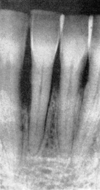
Figure 31-21 Widened periodontal space caused by trauma from occlusion. Note the increased density of the surrounding bone caused by new bone formation in response to increased occlusal forces.
Although microscopic measurements have determined normal variations in the PDL space width along the root surface, these are generally not detected radiographically. Thus, when seen on the radiographs, PDL space variations in width suggest that the tooth is being subjected to increased forces. Successful attempts to reinforce the periodontal structures by widening of the PDL space is accompanied by increased width of the lamina dura and sometimes by condensation of the perialveolar cancellous bone.
More advanced traumatic lesions may result in deep angular bone loss, which, when combined with marginal inflammation, may lead to intrabony pocket formation. In terminal stages, these lesions extend around the root apex, producing a wide, radiolucent periapical image (cavernous lesions).
 Science Transfer
Periapical radiographic examination should be part of each patient’s periodontal evaluation and should be coupled with a detailed recording of pocket depths, gingival margin location, and bleeding on probing. Radiographic evaluation should be updated every 2 years. Periapical radiographs often underestimate the amount of periodontal bone loss, and early changes are usually not detected. Significant interdental bone loss can occur and may not be detectable on periapical radiographs because the density of the intact buccal and lingual or palatal bone plates obscure changes that occur as the result of periodontitis. Comparison of periapical radiographs of the same area taken at different times will only be reliable in documenting dramatic changes in bone levels since variations in angulation of the beam, placement of the film, and development of the image make accurate measurements taken over time very difficult and unreliable.
Recent use of three-dimensional radiographic techniques with cone beam computed tomography (CBCT) gives a much more accurate picture of periodontal bone loss than two-dimensional radiographs and will be more widely used as this technology becomes available in more clinics.
Root resorption may also result from excessive forces on the periodontium, particularly those caused by orthodontic appliances. Although trauma from occlusion produces many areas of root resorption, these areas are usually of a magnitude insufficient to be detected radiographically.
Additional Radiographic Criteria
The following diagnostic criteria can be used as further aids in the radiographic identification of periodontal disease:
Skeletal Disturbances Manifested in the Jaws
Local or systemic diseases of the bones of the face can alter the cortical and trabecular architecture of the alveolar ridge and can mimic the radiographic appearance of periodontitis. Care should be taken in such cases to diagnose the primary cause of bone changes and avoid treatment delays.
Langerhans cell histiocytosis results from disturbances in immunoregulation, and its different forms comprise the diseases formerly called Hand-Schüller-Christian disease, Letterer-Siwe disease, Gaucher’s disease, and eosinophilic granuloma.5,34 The disease manifestations appear as single or multiple radiolucent areas, which may be unrelated to the teeth or may entail destruction of the tooth-supporting bone (Figure 31-24).
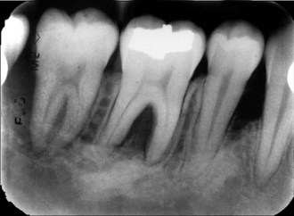
Figure 31-24 Vertical and furcational bone loss in an 18-year-old male patient caused by eosinophilic granuloma.
Malignancy, both primary and metastatic, can affect the alveolar ridge and often presents as periodontal disease. A uniform widening of the PDL can be an early sign of osteosarcoma. Irregular destruction of the periodontal bone without tooth displacement is frequently the result of squamous cell carcinoma or metastatic carcinoma.35
Multiple myeloma can cause multiple well-defined noncorticated radiolucencies of the jaws.
Metabolic diseases that affect calcium homeostasis, such as vitamin D deficiency (rickets or osteomalacia), hyperparathyroidism, and osteoporosis, diminish trabecular and cortical density and can lead to loss of lamina dura.30
In Paget’s disease the normal trabecular pattern is replaced by a hazy, diffuse meshwork of closely knit, fine trabecular markings, with absent lamina dura (Figure 31-25), or scattered radiolucent areas may contain irregularly shaped radiopaque zones.10,34
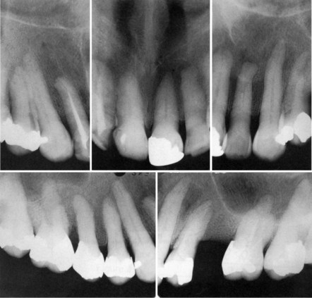
Figure 31-25 Altered trabecular pattern and diminution in the prominence of the lamina dura in Paget’s disease.
In scleroderma the periodontal ligament is uniformly widened at the expense of the surrounding alveolar bone1 (Figure 31-26).
Digital Intraoral Radiography
Intraoral digital radiographs offer several advantages over conventional film-based radiographs in clinical dentistry. The number of dentists using intraoral digital radiographs increases steadily, and some practices are now completely digital. Telediagnosis, videoconferencing, rapid image transmission among dentists and third parties, a seamless electronic patient record, and integration with computer-aided diagnostic software are areas in which digital information is revolutionizing dentistry.36,37
Two major digital intraoral systems are currently available.18 The first system uses charge-coupled devices (CCDs) or complementary metal oxide semiconductor (CMOS) receptors as detectors. These detectors are placed in the patient’s mouth and are linked by a wire to the computer. On radiation exposure, virtually in real time, the radiographic image appears on a computer screen. The detector is then moved to the next position, and so on, until the whole area of interest is imaged. The second system uses photostimulable phosphor (PSP) plates as detectors. PSP plates resemble film with one of the sides lined with a PSP coating. When interacting with x-rays, PSP stores energy, which it then releases on stimulation by light of an appropriate wavelength. PSP plates are placed and exposed similar to regular film. The exposed plates are placed on a plate scanner and scanned by a laser beam, and the radiographic image appears on the computer screen.18
Once captured and displayed, computer software can be used to enhance the digital image and increase its diagnostic efficacy.21 Exposure adjustment provides a balanced image that utilizes the complete scale of gray levels and does not suppress diagnostic information (Figure 31-27, compare A and B). A sharpening (edge enhancement) filter increases the definition and separation of adjacent structures (Figure 31-27, compare B and C). Inversion filters provide a negative of the image that sometimes might reveal disease not seen on the positive image (Figure 31-27, D). The ability to magnify the image allows close examination of the area of interest and detection of occult disease (Figure 31-27, E). Different image qualities allow better detection of dental disease. For example, high-contrast images favor caries detection, whereas low-contrast images permit a more accurate depiction of the alveolar crest. Digital images can be adjusted such that the contrast of the interproximal contacts can be enhanced for caries detection while the remainder of the image is not altered (Figure 31-27, F).
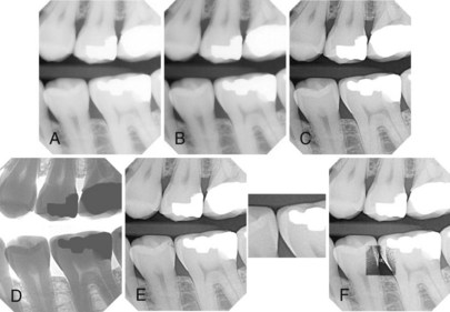
Figure 31-27 Various enhancement features help optimize the appearance of the radiographic image to improve diagnosis. Brightness and contrast of an underexposed image (A) is adjusted (B) to utilize the full gray scale. C, Sharpness of the image is then increased using “clear view” feature. D, “Invert” feature provides a negative of the image. E, “Zooming” function allows close examination of the interproximal space. F, Contrast of the interproximal area is maximized to aid in the diagnosis of possible caries.
(Courtesy Dexis Digital Diagnostic Imaging, Alpharetta, GA.)
Advantages of intraoral digital radiography include the speed of image capture and display; low x-ray exposure; ability to manipulate the image and maximize diagnostic efficacy; use of digital tools, such as linear, angular, and density measurements; improved patient education; ease of storage, transfer, and copying; and seamless integration with electronic patient record management or other software. Most studies conclude that the aid provided by digital radiographs in the diagnosis of common dental diseases such as caries is similar to that of conventional radiographs.
However, the proper use of digital intraoral radiographs requires familiarity with the digital nature of the images and an understanding of the principles of image manipulation by computer software.35 Although contrast and brightness adjustments can be used to refine the image, they cannot correct a grossly overexposed or underexposed projection. The ease of digital image acquisition should not replace correct detector placement and exposure techniques. Image enhancement should be used with caution and should be task oriented. For example, increased contrast might aid in caries diagnosis but lead to underestimation of the alveolar bone crest height. If properly used, intraoral digital radiography offers great benefits in the diagnosis of dental disease.35
Advanced Imaging Modalities
In the last decade, cone beam computed tomography (CBCT) has revolutionized the field of oral and maxillofacial imaging. CBCT technology and its use in evaluation of the implant patient are discussed in Chapter 71. However, CBCT finds application in almost every diagnostic task of clinical dentistry, including evaluation of periodontal and periapical structures. CBCT offers many advantages over conventional radiography, including the accurate three-dimensional imaging of teeth and supporting structures. Although not recommended for every dental patient, CBCT avoids the problems of geometric superimposition and unpredictable magnification and can provide valuable diagnostic information in periodontal evaluation.31
As discussed earlier, periapical and bite-wing radiographs provide information mostly for the interdental bone. However, a three-wall defect that preserves the buccal and/or lingual cortices can be difficult to diagnose, and the buccal, lingual and furcational periodontal bone levels are hard to evaluate in conventional radiographs. When clinical examination raises concerns for such areas, CBCT imaging can add diagnostic value. Figure 31-28 illustrates the CBCT diagnostic advantage in the evaluation of a three wall defect in the distal surface of tooth #31. Periapical radiograph (Figure 31-28, A) presents normal bone height at the mesial and distal surface of #31. CBCT sections (Figure 31-28, A to C) clearly demonstrate a three-wall defect on the distal surface of #31. Note that the buccal and lingual cortical plates are well preserved. For this reason, the periodontal defect is not depicted by the periapical radiograph.
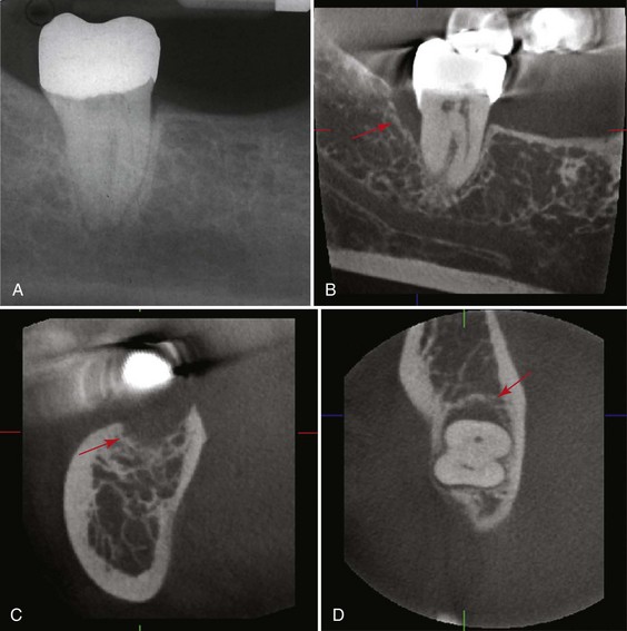
Figure 31-28 Periapical radiograph (A) and sagittal (B), cross-sectional (C), and axial (D) cone-beam computed tomography (CBCT) sections of tooth #31. No pathology is detected on the periapical radiograph. However, CBCT images clearly illustrate a deep vertical three-wall defect on the distal surface of #31 (red arrow).
1 Alexandridis C, White SC. Periodontal ligament changes in patients with progressive systemic sclerosis. Oral Surg. 1984;58:113.
2 Armitage G. Periodontal diseases: diagnosis. Ann Periodontol. 1996;1:37.
3 Bender IB, Seltzer S. Roentgenographic and direct observation of experimental lesions in bone. I. J Am Dent Assoc. 1961;62:152.
4 Bender IB, Seltzer S. Roentgenographic and direct observation of experimental lesions in bone. II. J Am Dent Assoc. 1961;62:708.
5 Cotran RS, Kumar V, Robbins SL. Robbins pathologic basis of disease, ed 5. Philadelphia: Saunders; 1994.
8 Fitzgerald GM. Dental radiography. IV. The voltage factor (kp). J Am Dent Assoc. 1950;41:19.
10 Glickman I, Glidden S. Paget’s disease of the maxillae and mandible: clinical analysis and case reports. J Am Dent Assoc. 1942;29:2144.
11 Greenstein G, Polson A, Iker H, et al. Associations between crestal lamina dura and periodontal status. J Periodontol. 1981;52:312.
12 Hausmann E, Allen K, Clerehugh V. What alveolar crest level on a bite-wing radiograph represents bone loss? J Periodontol. 1991;62:570.
13 Hirschfeld I. Interdental canals. J Am Dent Assoc. 1927;14:617.
14 Källestål C, Matsson L. Criteria for assessment of interproximal bone loss on bite-wing radiographs in adolescents. J Clin Periodontol. 1989;16:300.
15 Manson JD. The lamina dura. Oral Surg. 1963;16:432.
16 Nicopoulos-Karayianni K, Mombelli A, Lang NO. Diagnostic problems of periodontitis-like lesions caused by eosinophilic granuloma. J Clin Periodontol. 1989;16:505.
17 Parfitt GJ. An investigation of the normal variations in alveolar bone trabeculations. Oral Surg. 1962;15:1453.
18 Parks ET, Williamson GF. Digital radiography: an overview. J Contemp Dent Pract. 2002;3:23.
19 Patur B, Glickman I. Roentgenographic evaluation of alveolar bone changes in periodontal disease. J Clin North Am. 1960;4:47.
20 Pauls V, Trott JR. A radiological study of experimentally produced lesions in bone. Dent Pract. 1966;16:254.
21 Preston JD. Digital radiography: not if, but when. CDA J. 1999;27:935.
23 Prichard JF. Advanced periodontal disease: surgical and prosthetic management, ed 2. Philadelphia: Saunders; 1972.
24 Puckett J. A device for comparing roentgenograms of the same mouth. J Periodontol. 1968;39:38.
25 Ramadan ABE, Mitchell DF. A roentgenographic study of experimental bone destruction. Oral Surg. 1962;15:934.
26 Rams TE, Listgarten MA, Slots J. Utility of radiographic crestal lamina dura for predicting periodontal disease activity. J Clin Periodontol. 1995;21:571.
27 Regan JE, Mitchell DF. Roentgenographic and dissection measurements of alveolar crest height. J Am Dent Assoc. 1962;66:356.
28 Rees TD, Biggs NL, Collings CK. Radiographic interpretation of periodontal osseous lesions. Oral Surg Oral Med Oral Pathol. 1962;5:934.
29 Ritchey B, Orban B. The crests of the interdental septa. J Periodontol. 1953;24:75.
30 Rosenberg EH, Guralnick WC. Hyperparathyroidism. Oral Surg. 1962;15(suppl 2):84.
31 Rosling B, Hollender L, Nyman S, et al. A radiographic method for assessing changes in alveolar bone height following periodontal therapy. J Clin Periodontol. 1975;2:211.
32 Theilade J. An evaluation of the reliability of radiographs in the measurement of bone loss in periodontal disease. J Periodontol. 1960;31:143.
33 Tyndall A, Rathore S: Cone-beam CT diagnostic applications: caries, periodontal bone assessment, and endodontic applications. Dent Clin North Am. 2008;52:825.
34 Van der Linden LWJ, Van Aken J. The periodontal ligament in the roentgenogram. J Periodontol. 1970;41:243.
35 Waldron CA. Bone pathology. In: Neville BW, Damm DD, Allen CM, et al, editors. Oral and maxillofacial pathology. Philadelphia: Saunders, 1995.
36 White SC, Pharoah MJ. Oral radiology: principles and interpretation, ed 6. St Louis: Mosby, Elsevier; 2009.
37 White SC, Yoon DC, Tetradis S. Digital radiography in dentistry: what it should do for you? CDA J. 1999;27:942.