CHAPTER 75C Technologic Advances in Implant Surgery
Computer-Assisted Implant Surgery
Implant surgical procedures have more or less remained the same since the introduction of osseointegrated dental implants. Briefly, implant placement surgery involves the use of a full-thickness flap elevation and a sequential series of drills with increasing diameters under profuse irrigation to create a precise osteotomy site in the bone for the placement of a dental implant (see Chapter 71). The site is prepared, and the implant positioned to avoid important anatomic structures, such as the inferior alveolar nerve, sinus cavities, and teeth, and to optimally support and emulate the planned prosthetic tooth replacement(s). Proper implant position is important for optimal function and esthetics.
Clinicians determine implant positions based on presurgical diagnostic imaging, study models, and the use of a diagnostic wax-up of the planned tooth replacement(s). The actual or final position of the implant(s) results from the surgeon’s interpretation of diagnostic information and his or her ability to translate that information to the patient at surgery. Most often, the surgical “guide” between the diagnostic information and the patient is an acrylic stent, fabricated by a laboratory technician, that may or may not have precise guide channels for implant positioning. Therefore inaccuracies in the stent fabrication and movement of the stent during surgery, as well as variations in the use of the stent during surgery, can lead to imprecise implant positioning.
Recent advances in implant surgical technology include the use of the following:
CAIS is the most sophisticated and perhaps the most promising of these technologies because it has the greatest potential to reduce surgical time, minimize surgical invasiveness, and result in a more precise translation of implant planning to the actual surgical procedure.18 Understandably, CAIS is also the technique that requires the greatest amount of preparation and coordination of the patient, image data, and surgical instrumentation. The following provides a conceptual overview of the techniques and terminology used in CAIS.
Computer-Assisted Implant Surgery
Uses and Requirements
Computerized navigation surgery evolved from early applications in neurosurgical procedures and continues to evolve today with applications in many surgical specialties.13,15 Clearly, the advantage of using a computer to assist surgery is the precision that it offers. There is also a real-time safety control obtained with multiple imaging sources facilitating a minimally invasive approach to surgical procedures. As in medicine, 3D imaging is used in dentistry to facilitate presurgical planning and to guide the surgical placement of dental implants. This allows precise positioning while avoiding injury to nearby important anatomic structures. Several different approaches to computers have been used in dental implant surgery, from simple imaging software to visualize the implant positions in a 3D virtual patient to more complex, simultaneous image monitoring and instrument navigation used to perform surgery.4
The use of CAIS requires precise and continuous coordination of the patient, the image data, and the surgical instrumentation. Therefore CAIS requires an accurate alignment (identification and registration) of the patient with the patient’s image data (3D CT scan data) and a system of tracking the precise movements of the surgical instrumentation (e.g., handpiece, drills) in relation to the actual patient. A variety of systems have been developed to acquire and register image data and to coordinate and track movements. These methods are generically described in the following sections.
Sequence of Steps
The clinical sequence of steps required for CAIS is as follows:
Preoperative Data Acquisition
CT scans and the more-recent cone-beam CT (CBCT) scans are widely used for 3D patient imaging (see Chapter 70). Factors that must be considered when deciding to use a CT scan include radiation exposure, limitations in accuracy, and the possibility of diffracted images as a result of metallic restorations. The evolution of scanner technology (spiral CT scan, CBCT scan) has made it possible to reduce the radiation dose to the level of a conventional panoramic radiograph while maintaining adequate diagnostic quality for preoperative implant planning.6
Similar to implant planning using conventional diagnostic methods, radiographically identifiable markers are important for CAIS. However, unlike conventional planning, in which orientation and simulation of implant positions are related to the planned prosthetic crown positions, CAIS markers must relate the image data to the actual patient anatomy. In other words, the position of the surgical instrumentation (and ultimately the implant) must be related to the scan image data of the patient’s jaw morphology. Thus it is critically important to scan the patient with markers that are identified in the scan and correlated to the patient at surgery. Markers can be anatomic markers, such as teeth or specific bony landmarks, or artificial markers (fiducial), such as small tacks or screws that are secured in the bone.
Identification and Registration
After scan acquisition, the 3D image data of the patient’s jaw(s) are interpreted by software as anatomic geometric elements. As previously stated, a sufficient number of markers (anatomic or fiducial) must be identified in the patient’s mouth to correlate the image data with the patient anatomy. Several devices have been used to capture the actual patient anatomy for registration with the scan data, including a touch pointer and an ultrasound probe. The touch pointer allows the operator to touch specific anatomic points (or fiducial markers) while a tracking device “sees” the instrument and records each point of reference. This device is fairly accurate, but if the clinician is not careful, there is a tendency to define points that are not in contact to a real surface, thus creating a false mapping. The ultrasound probe has a lower accuracy than the touch pointer but has the advantage of being able to capture continuous data of bone morphology through the mucosa or gingiva. Echo quality is subject to variations with the type of penetrated tissue.
Matching between the geometry of the image data with the patient anatomy is called registration. Five registration methods are used to compare anatomic points of the preoperative image data and the intraoperative patient anatomy: (1) point-based, (2) line-based or curve-based, (3) surface-based, (4) volume-based, and (5) projective methods. Point-based and line-based methods are described here to illustrate the requirements for an adequate registration.
In the point-based method, a few particular points are identified in the preoperative image data and the patient anatomy. These can be natural (anatomic points) or artificial (fiducial) markers. In either case, points must be well defined and stable so that they can be precisely measured. The operator can manually click, with a tracking device, on the point in the patient corresponding to the image point. After several points are matched, the computer calculates a transformation equation that minimizes the mean distance between matched points to complete the registration. Three nonaligned points are necessary to obtain a nonambiguous result. The registration accuracy can be predicted, depending on the distribution of points (e.g., an equilateral tripod will give more accurate results than three co-linear points).7,12
The most intuitive algorithm may be the Hough transformation, in which the most simple geometric invariant, the distances between points, are computed, compared, and used to find a triangle in the preoperative set of points and a triangle in the intraoperative set of points that shares similar edge lengths. The triangle points are then registered using the best-fit algorithm. Once a first estimate of the transformation has been computed, the clinician can apply the transformation to the intraoperative points.
Line-based or curve-based methods are derived from point-based methods but require a few lines or curves to be measured and identified. Artificial lines can be extracted from the CT scan image data and measured intraoperatively by the operator with the tracking device. All lines and surfaces measured on image planning (after segmentation of anatomic structure of the jawbone in the CT scan), and the points taken on the patient anatomy by the tracking device are known as a set of points. These sets may be dense or sparse; a segmented bone surface may have hundreds or thousands of points. However, it is not practical to measure hundreds of points.
When the segmented surface is dense, one can assume that almost all points measured with the tracking device will be identified as points of the segmented surface. Thus, algorithms developed for the point-based registration, based on identification of matching between the preoperative and the intraoperative data, can be easily adapted. However, the number of possible errors in the identification process increases dramatically in line-based or curve-based methods.
Navigation and Positional Tracking
Numerous commercial products exist for navigation or positional tracking, but few meet the computer-aided surgery (CAS) requirements in terms of accuracy (about 1 mm in one cubic meter), reliability, and clinical usability. The “real-time” navigational technology is based on the global positioning system (GPS) technology.16 Some of the technologies used in medical CAS to track movement include mechanical, magnetic, and optical tracking systems.
Mechanical tracking systems use a six-axis coding robot with a passive arm. The system is very reliable and highly accurate but has limitations when more than one instrument or patient marker needs to be located. Thus mechanical tracking is less desirable for CAIS, which requires the use of several different instruments and multiple markers.
Magnetic tracking systems use a magnetic source and a field receiver. The system loses accuracy in the presence of magnetic field interference. Relative inaccuracies result from changes in the magnetic field, which may be caused by any metallic mass that may be present, such as a drill motor (with or without activation).2,3 Thus the obligatory presence of drill motors in the operatory during implant surgery makes magnetic trackers impractical for CAIS.
Optical tracking systems are recognized for their dependability and accuracy. Positioning is made by intersecting the vision plane between two or three cameras to locate markers with stereovision. A passive system absorbs and processes ambient light, whereas an active system interprets reflected light.
Active markers with infrared light–emitting diodes (IRED) have been widely used with superb accuracy but are sensitive to reflections and interference with the line of sight between the IRED markers and the cameras.9,11 Although variations in optical localizers are adequate for medical applications,1,5 they need to be improved for use in dental implant surgery. This is particularly problematic with the typical seating arrangement of surgeon and assistant (i.e., the direct line of sight to the cameras may be interrupted by the operators). A stereovision with natural-light cameras is a less expensive alternative compared with IRED. However, natural-light systems are more sensitive to surrounding light, background, and the shape of markers. In comparison, infrared cameras are less sensitive to these light variations.
With optical tracking devices, the surrounding light in the operatory is important, and a headset light is preferred with a camera sensitive to natural light. Patient motion will be tracked efficiently if the marker is stable during surgery. In case of loose teeth or unstable markers, cortical bone screws should be used.
External Viewer, Augmented Reality, and 3D Projection Screens
Once registration between the data and the actual patient has been established, the instrumentation can be coordinated with the system and observed by the surgeon/operator (Figures 75C-1 and 75C-2). Instrument movement relative to the image data (and through registration to the patient) may be viewed on an external monitor, visually projected in the surgeon’s field of vision (resulting in a superimposed visual image seen over the surgical field) using a head-mounted projection system or projected on a 3D projection screen (Figure 75C-3).20 In this manner, the image on the external monitor (see Figure 75C-2), the surgical field, or the 3D projection screen (Figures 75C-4 and 75C-5) will guide the surgeon to perform the planned procedure.
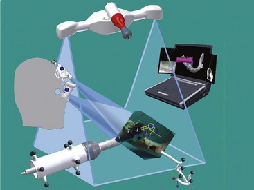
Figure 75C-1 Global setup for surgical navigation. The basic setup for a navigation system consists of stereovision cameras with several tools. The contra-angle probe, the ultrasound probe and the patient jig need to have markers, which are tracked by the cameras. The occlusal stent, with markers in the standard process and without markers in ultrasound registration, used during computed tomography (CT) scan acquisition will be recognized in its three dimensions for prosthetic planning.
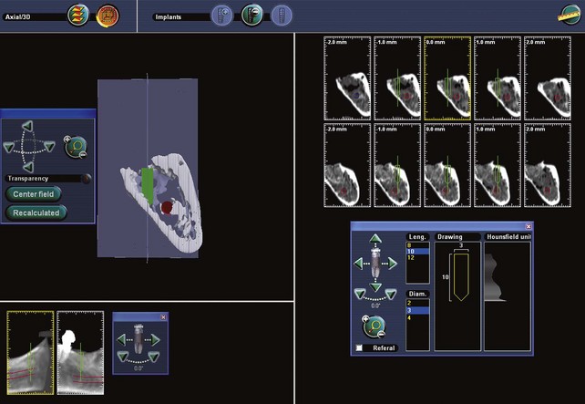
Figure 75C-2 Images of computer screen and surgeon’s view of computer-aided implant surgery (CAIS) navigation simulated with dry mandible. During navigation, the surgeon concentrates on visual cues seen on the eye viewer.
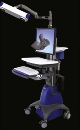
Figure 75C-3 Dental implant real-time navigation system with infrared stereovision cameras and a three-dimensional (3D) monitor display showing the reconstruction of a computed tomography (CT) scanned mandible.
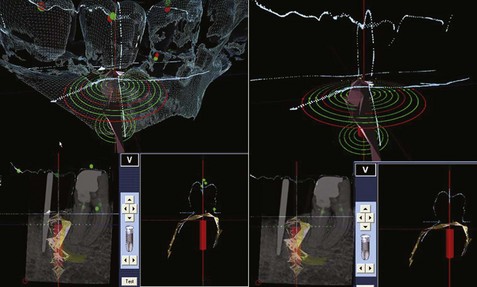
Figure 75C-4 Conventional x-ray and ultrasound acquisition for alveolar bone topography (in light brown, lower left) combined with an optical scan image showing crown and alveolar bone morphology (dark green). The implant position is shown in red. This two-dimensional view is obtained without a computed tomography (CT) scan.
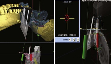
Figure 75C-5 Screen views available during surgery. Upper left, Simulated implants in green and red. The computed tomography (CT) scan reconstruction of the mandible and teeth is observed in yellow. Surface mapping of bone and crown morphology (dark green/blue) obtained from ultrasound or optical scanner. The computer compares the data from the three-dimensional (3D) topography to the two-dimensional (2D) x-ray. Lower left, The 2D x-ray is matched to a 3D topography of the patient “matrix” with the simulated implant positions in green and red. Upper right, The target and position of the drill/implant are observed. Lower right: Real-time navigation with a combination of superimposed images from a 2D x-ray, optical scanner, CT scan, and 3D ultrasound.
Side viewers display target data in two dimensions and require the surgeon to look away from the surgical field. However, see-through viewers display target data transparently in the surgeon’s field of view and allow the operator to observe the surgical field continuously. An augmented-reality viewer allows the surgeon to see target data in three dimensions, superimposed over the surgical site through projected images in both eyes.21 The augmented-reality method allows the operator to adapt to the system more naturally and therefore more rapidly, but there do not appear to be advantages over the use of a two-dimensional (2D) side-viewer devices in terms of accuracy.17 Both systems allow simultaneous viewing of virtual information of the implant (axis and target) and a real vision of the surgical site. Augmented-reality devices are very sensitive to calibration before surgery and require care and monitoring intraoperatively to prevent misalignment during the surgery. The relative stability of a headset is critical to maintaining accuracy.
Alternatively, 3D projection screens provide a “real 3D vision” viewed on a specialized monitor (see Figure 75C-3) without the need for viewers (i.e., operator glasses).
Two types of 3D projection screens are available, as follows:
This 3D projection screen technology cannot provide a true holographic 3D view because of the eye’s plane of focus on a flat screen, but it does provide a 3D “real volumetric view.” In addition to this improvement in 3D vision, a 3D sequence of images can be modified for specific applications such as navigation. For example, a 3D sequence of 8 views can be modified to facilitate the observation of a projected view of the object at 90° with a minimal head side shift of only 5 degrees. These real-time, 3D front and side views provide intuitive 3D data views in spite of the 2D parameters used to visualize them.
Advantages and Disadvantages
Benefits and advantages of computer-assisted implant surgery include the following:
Conclusion
The use of computer-assisted implant surgery with simultaneous tracking and “guidance” of the implant instrumentation facilitates the precise surgical placement of implants with “real-time” visual assessment of anatomic structures. The system is complex, and several steps must be coordinated for CAIS to be accurate and useful. Newer generation systems are becoming more intuitive with 3D projected vision with improved software interface for the operator.
CAIS systems are expensive and therefore not readily available. Surgeons require training and experience to perform CAIS well. As a result, the more complex or difficult cases may be the most likely types of patients to benefit from the use of CAIS. The newer systems are continuing to improve, which may make utilization of CAIS more accessible to surgeons and patients.
 Science Transfer
Computer-assisted surgery (CAS) involves the use of digitalized three-dimensional (3D) data obtained by the use of cone-beam computer-generated radiographs, markers placed in a surgical stent, and a computer-directed guidance system used during implant placement. This new technology is being developed to enhance accuracy of implant placement and to reduce angulation and alignment errors. At present, these systems require extensive training by the clinician, and the intraoperative surgical guidance methodology is being improved so that this approach can have wider utilization.
1 Armangue X, Salvi J. Overall view regarding fundamental matrix estimation. Image Vision Comput. 2003;1:205.
2 Birkfellner W, Watzinger F, Wanschitz F, et al. Systematic distortions in magnetic position digitizers. Medical physics. 1998;25:2242-2248.
3 Birkfellner W, Watzinger F, Wanschitz F, et al. Calibration of tracking systems in a surgical environment. IEEE transactions on medical imaging. 1998;17:737-742.
4 Casap N, Tarazi E, Wexler A, et al. Intraoperative computerized navigation for flapless implant surgery and immediate loading in the edentulous mandible. The Int J Oral Maxillofac Implants. 2005;20:92-98.
5 Chassat F, Lavallee S. Experimental protocol of accuracy evaluation of 6D localizers for computer integrated surgery: application for four optical localizers. Tokyo. 2002.
6 Diederichs CG, Engelke WG, Richter B, et al. Must radiation dose for CT of the maxilla and mandible be higher than that for conventional panoramic radiography? AJNR Am J Neuroradiol. 1996;17:1758-1760.
7 Fitzpatrick JM, West JB, Maurer CRJr. Predicting error in rigid-body point-based registration. IEEE Transactions on Medical Imaging. 1998;17:694-702.
8 Fortin T, Coudert JL, Champleboux G, et al. Computer-assisted dental implant surgery using computed tomography. Journal of image guided surgery. 1995;1:53-58.
9 Kai J, Shiomi H, Sasama T, et al. Optical high-precision three-dimensional position measurement system suitable for head motion tracking in frameless stereotactic radiosurgery. Comput Aided Surg. 1998;3:257-263.
10 Klein M, Abrams M. Computer-guided surgery utilizing a computer-milled surgical template. Pract Proced Aesthet Dent. 2001;13:165-169. quiz 170
11 Malamas E, Petrakis E, et al. A survey of industrial vision systems: applications. Image Vision Comput. 2003;21:171.
12 Pennec X, Thirion JP. A framework for uncertainty and validation of 3D registration methods based on points and frames. Int J Comput Vision. 1997;25:203.
13 Roberts DW, Strohbehn JW, Hatch JF, et al. A frameless stereotaxic integration of computerized tomographic imaging and the operating microscope. J Neurosurg. 1986;65:545-549.
14 Sarment DP, Al-Shammari K, Kazor CE. Stereolithographic surgical templates for placement of dental implants in complex cases. Int J Periodontics Restorative Dent. 2003;23:287-295.
15 Satava RM. Emerging technologies for surgery in the 21st century. Arch Surg. 1999;134:1197-1202.
16 Siessegger M, Schneider BT, Mischkowski RA, et al. Use of an image-guided navigation system in dental implant surgery in anatomically complex operation sites. J Craniomaxillofac Surg. 2001;29:276-281.
17 Tian X, Ling KV, Ng WS. Magnetic tracker calibration for an augmented reality system for therapy. Proceedings of the Institution of Mechanical Engineers. 2001;215:51-59.
18 Verstreken K, Van Cleynenbreugel J, Marchal G, et al. Computer-assisted planning of oral implant surgery: a three-dimensional approach. Int J Oral Maxillofac implants. 1996;11:806-810.
19 Verstreken K, Van Cleynenbreugel J, Martens K, et al. An image-guided planning system for endosseous oral implants. IEEE Transactions on Medical Imaging. 1998;17:842-852.
20 Wanschitz F, Birkfellner W, Figl M, et al. Computer-enhanced stereoscopic vision in a head-mounted display for oral implant surgery. Clin Oral Implants Res. 2002;13:610-616.
21 Zamorano LJ, Nolte L, Kadi AM, Jiang Z. Interactive intraoperative localization using an infrared-based system. Neurol Res. 1993;15:290-298.