CHAPTER 70 Diagnostic Imaging for the Implant Patient
Several radiographic imaging options are available for diagnosis and treatment planning of patients receiving dental implants.2,21 Options range from standard projections routinely available in the dental office to more complex radiographic techniques typically available only in radiology centers. Standard projections include intraoral (periapical, occlusal) and extraoral (panoramic, lateral cephalometric) radiographs. More complex imaging techniques include conventional x-ray tomography, computed tomography (CT), and cone-beam CT (CBCT). The CT and CBCT image data files can be reformatted and viewed on a personal computer, using simulation software, making the diagnosis and treatment-planning process interactive and visually more meaningful. Often, combinations of various modalities are used because no single modality can provide all information pertinent to the radiographic evaluation of the implant patient. Familiarity with the benefits and limitations of various techniques and awareness of the specific clinical questions that need to be answered should guide the decision-making process and selection of radiographic examinations for individual patients.
Multiple factors influence the selection of radiographic technique(s) for a particular case, including cost, availability, radiation exposure, and case type. The decision is a balance between these factors and the desire to minimize risk of complications to the patient. Accurately identifying vital anatomic structures and being able to perform implant placement surgery without injury to these structures are critical to treatment success. Diagnostic imaging techniques must always be interpreted in conjunction with a good clinical examination.
This chapter discusses common imaging techniques used for evaluation of the implant patient. Indications for each technique are outlined, along with the advantages and limitations.
Standard Projections
Standard diagnostic imaging modalities include periapical, panoramic, lateral cephalometric, and occlusal radiographs. The advantages and disadvantages of each modality are summarized in Table 70-1.
TABLE 70-1 Advantages and Disadvantages of the Various Radiographic Projections
| Modality | Advantages | Disadvantages |
|---|---|---|
| Periapical and occlusal radiography | High resolution and detail, easy acquisition, low exposure, inexpensive. | Unpredictable magnification, small imaged area, 2D representation of anatomy. |
| Panoramic radiography | Easy to acquire, images whole ridge, low exposure, inexpensive. | Unpredictable magnification, 2D representation of anatomy, not detailed. |
| Lateral cephalometric radiography | Easy to acquire, predictable magnification, low exposure, inexpensive. | Limited use in area of midline, 2D representation of anatomy. |
| Tomography | 3D representation, predictable magnification, sufficient detail, low exposure, images area of interest only. | Requires special equipment, for evaluation of multiple sites can be a lengthy procedure because the patient must be repositioned for each site, expensive. |
| Computed tomography (CT) | 3D representation, predictable magnification, sufficient detail, digital format, images whole arch. | Requires special equipment, expensive, high-exposure dose. |
| Cone-beam computed tomography (CBCT) | 3D representation, predictable magnification, sufficient detail, digital format, images whole arch, low dose. | Requires special equipment, expensive. |
2D, Two-dimensional; 3D, three-dimensional.
Periapical Radiographs
Periapical radiographs offer great advantages during the evaluation of the implant patient.22,24 They provide an overall assessment of the quantity and quality of the edentulous alveolar ridge and the adjacent teeth. They are easy to obtain in the dental office, are inexpensive, and deliver low radiation to the patient (Table 70-2). Dentists are familiar with the depicted anatomy and possible pathology. Because these direct-exposure projections do not use intensifying screens, intraoral radiographs offer the highest detail and spatial resolution of all radiographic modalities (Figure 70-1). Thus, these films are the projection of choice when subtle pathology, such as a retained root tip, needs to be detected and evaluated.
TABLE 70-2 Radiation Dose (Effective Dose in µSv) Received from Common Projections during Evaluation of the Implant Patient
| Modality | Effective Dose (µSv) |
|---|---|
| Full-mouth x-ray (FMX) series | 35–388 |
| Panoramic | 9–26 |
| Conventional tomography | 26–187 |
| CT of the head | 2000 |
| Large field-of-view CBCT | |
| NewTom 3G | 68 |
| i-CAT: next generation portrait mode | 74 |
| Small field-of-view CBCT | |
| Accuitomo 3DX | 20 |
| Galileos default exposure | 70 |
CT, Computed tomography; CBCT, cone-beam computed tomography.
Data from Ludlow JB, Davies-Ludlow LE, White SC: J Am Dent Assoc 139:1237, 2008.
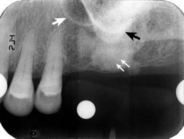
Figure 70-1 The periapical radiograph offers a high-resolution, detailed image of the edentulous area. Healing of the extraction socket with dense bone (socket sclerosis) can be seen (small white arrows). Some anatomic structures, such as the maxillary sinus (large white arrow) and the zygomatic process of the maxilla (black arrow), can also be visualized.
The most significant disadvantage of periapical radiographs is their susceptibility to unpredictable magnification of anatomic structures, which does not allow reliable measurements.19 Foreshortening or elongation can be minimized by the use of paralleling technique. However, distortion is particularly accentuated in edentulous areas, where missing teeth and resorption of the alveolus necessitate film placement at significant angulation in relation to the long axis of the teeth and alveolar bone. Additionally, periapical radiographs are two-dimensional representations of three-dimensional objects and do not provide any information of the buccal-lingual dimension of the alveolar ridge. Structures that are distinctly separated in the buccal-lingual dimension appear to be overlapping. Also, the periapical image is limited by the size of film being used. Often, it is not possible to image the entire height of the remaining alveolar ridge, and when extensive mesial-distal areas need to be evaluated, multiple periapical films are required.
In summary, periapical radiographs are useful screening images that offer a detailed view of a small area of the alveolar arch. Limitations that must be considered include the possibility of distortion and the two-dimensional representation of anatomic structures.
Occlusal Radiographs
Occlusal radiographs are intraoral projections that offer easy, economic, low-dose, and high-resolution images covering a larger area than periapical films.24 Depending on film placement and the angulation of the x-ray tube, occlusal films can provide a cross-sectional image of the mandible or can depict an extended area of the edentulous ridge. Cross-sectional occlusal films allow the measurement of the buccal-lingual dimension of the mandible. This can be an important consideration when planning implants in the severely resorbed mandible. Occlusal films have the same limitations of distortion and overlapping anatomy as periapical films.
In summary, occlusal film projections are good screening images that can provide an overview of the mandibular width or can visualize larger areas of alveolar ridge compared with periapical film projections.
Panoramic Radiographs
Panoramic radiographs are often used in the evaluation of the implant patient because they offer several advantages over other modalities.20 Panoramic films deliver low radiation (see Table 70-2) to provide a broad picture of both arches and thus allow assessment of extensive edentulous areas, angulation of existing teeth and occlusal plane, and important anatomy in implant treatment planning such as the maxillary sinus, nasal cavity, mental foramen, and mandibular canal (Figure 70-2). Panoramic units are widely available and easy to operate, and dentists are familiar with the anatomy and pathology depicted by the images. Similar to intraoral projections, panoramic images are two-dimensional and thus do not offer diagnostic information for the buccal-lingual width of the alveolar arch.
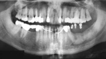
Figure 70-2 Panoramic radiograph. Both jaws are visualized on the same film. An overall assessment of superoinferior and mesial-distal dimensions of the alveolar ridge can be formulated. Tooth and root positions relative to planned implant sites can be evaluated. Important anatomic structures, such as the maxillary sinus and mandibular canal, can be identified.
Panoramic images appear intuitively familiar. However, they combine characteristic physical and radiographic principles that make them distinct from other intraoral and extraoral radiographs. Although outside the scope of this chapter, familiarity with the principles underlying panoramic radiography is central in understanding, and thus compensating for, the limitations and constraints of the images. The reader is referred to other textbooks for detailed discussion of this topic.9,14 Briefly, the existence of ghost shadows, unpredictable horizontal and vertical magnification, distortion of structures outside the focal trough, projection geometry generated by the negative vertical angulation of the x-ray beam, and propensity to patient-positioning errors do not allow consistently detailed and accurate measurements to be generated. As a result, panoramic radiographs do not provide the highly detailed images that are generated by intraoral radiographs.
Measurement distortion is more prevalent and varies across the radiographic image. On average, panoramic radiographs are 25% magnifications of actual size. Implant manufacturers often provide transparency sheets with implant size outlines of 25% magnification. However, it is important to appreciate that the 25% magnification is an estimate. The actual magnification may range from 10% to 30% in different areas within the same film and depends greatly on patient positioning during panoramic radiography. For this reason, precise measurements on panoramic projections are not possible. Nonetheless, panoramic radiographs offer an overall view of the maxilla and mandible that can be used to estimate bone measurements and evaluate the approximate relationships between teeth and other anatomic structures. More precise diagnostic imaging should be used to measure proximity of critical anatomic structures, such as the maxillary sinus or the mandibular canal, to proposed implant positions.
In summary, panoramic projections are useful screening images of the jaws for approximations and relative special relationships. However, because of magnification and distortion errors, panoramic films should not be used for detailed measurements of proposed implant sites.
Lateral Cephalometric Radiographs
Lateral cephalometric radiographs are occasionally used to evaluate potential implant patients.21 These films provide useful information for the cortical thickness, height, and width of the alveolar ridge at the midline, as well as the skeletal relationship between maxilla and mandible and facial profile. Lateral cephalometric radiographs are low in cost, readily available, and easy to interpret and have a predictable magnification of the depicted structures. However, their use for the implant patient is limited to structures at the midline, with minimal usefulness for other areas of the jaws.
In summary, lateral cephalometric radiographs have a limited use in implant treatment planning.
Cross-Sectional Imaging
Cross-sectional diagnostic imaging modalities include conventional x-ray tomography, CT, and CBCT.
Conventional X-ray Tomography
In conventional tomography the x-ray source and the film are connected and rotate around a fixed point (fulcrum), usually performing simple (linear) or complex (elliptic or hypocycloidal) tomographic motions.4 Structures that are in the plane (focal area) of rotation are depicted in sharp focus, while structures outside the plane of rotation are blurred. The resulting image is a true cross section of the structures within the imaged plane, which is perpendicular to the x-ray beam (Figure 70-3).
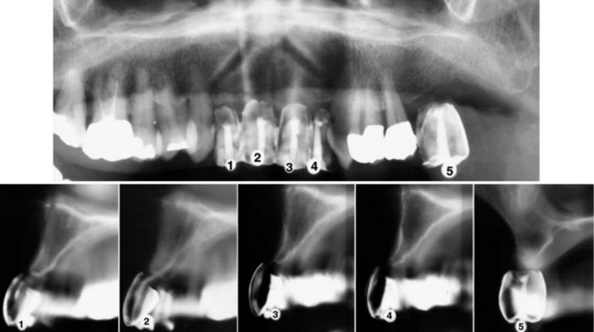
Figure 70-3 A, Panoramic radiograph with markers indicating the five prospective implant sites. B, Conventional tomography of the same five prospective implant sites in the anterior and posterior maxilla. Note the tooth-shaped markers used that allow the clinician to evaluate bone dimensions in the jaw relative to the planned prosthetic tooth position. The cortical outline of the alveolar ridge and the floor of the nasal cavity or maxillary sinus can be seen. Accurate measurements of the height and buccolingual width can be made. Although conventional x-ray tomographic images focus on a specific area, the image is often difficult to read because of the blurring of structures on either side of the plane.
Proper patient positioning is essential to generate true cross sections of the jaws.5,7 The curvature of the alveolar ridge is usually evaluated from scout films, such as submentovertex (SMV) or occlusal projections, or from dental models. The imaged structures are always magnified. However, the magnification is uniform, predictable, and specific to the equipment used for the acquisition of the image. Overlay templates with magnification values that match the magnification of the equipment can be used to measure dimensions on the film reliably.
Conventional x-ray tomography offers many advantages in evaluation of the implant patient.10,11 With proper patient positioning, it can generate true cross sections of the alveolar ridge and provide diagnostic information of the cortical thickness, trabecular density, height and width of the alveolus, and location of vital anatomic structures. The generated images usually provide adequate resolution.
The specialized equipment used for conventional x-ray tomography requires familiarity with the image acquisition. Interpretation of the images is sometimes challenging, especially when the anatomy of the jaws has been altered because of traumatic extractions, alveolar ridge resorption, or other conditions. Although images are true cross-sections, the progressive blurring of structures outside the focal plane does not allow sharply defined tomographic slices, and prominent opaque structures can cast “ghost” shadows and complicate the images. Another drawback of conventional tomography is that the procedure can be rather lengthy when multiple edentulous areas are evaluated. Finally, the cost of conventional x-ray tomography is higher than standard intraoral and extraoral radiographs.
In summary, conventional tomography offers true cross-sectional images of the alveolar ridge and is particularly useful during placement of single or few implants. Limitations of conventional tomography include blurring of images by structures on either side of the focal plane and the time required to reposition the patient for each image.
Computed Tomography
CT scanning is widely used in the evaluation of the implant patient.3,8 The detailed physics behind image acquisition during CT scanning are beyond the scope of this chapter.4 In general, a thin fan-beam of x-rays rotates around the patient to generate in one revolution a thin (0.5 to 1.0 mm wide) axial slice of the area of interest (Figure 70-4, A). Multiple overlapping axial slices are obtained by several revolutions of the x-ray beam until the whole area of interest is covered. These slices are then used to generate, with the help of a computer and sophisticated algorithms, a digital volume of the imaged object. The construction of this three-dimensional digital map of the jaws is the advantage of CT during evaluation of the implant patient. Specialized software can be used to generate appropriate views that best depict the dimensions of the jaws and the location of important anatomic structures.
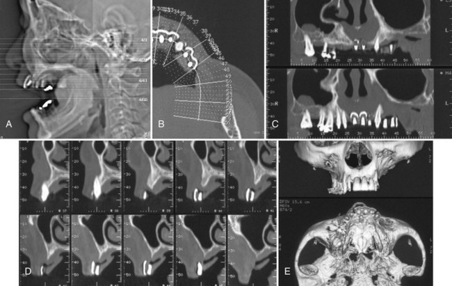
Figure 70-4 Computed tomography (CT) examination for evaluation of edentulous maxilla before implant placement. A, Scout view of the patient’s head; axial sections through the area of interest are indicated. B, Axial slice through the markers is used to display the orientation of the panoramic and cross-sectional images through the alveolar ridge. C, Panoramic views through the alveolar ridge demonstrate the relation of the markers to adjacent teeth. D, Cross-sectional slices through the area of the markers reveal the height and buccolingual dimension of the alveolar ridge, as well as the relation of the markers to the ridge. E, Three-dimensional reconstructions provide an overall impression of the bone contours and shape of the alveolar ridge.
Typical dental views obtained from a CT scan include axial (Figure 70-4, B), panoramic (Figure 70-4, C), and cross-sectional (Figure 70-4, D) views of the jaws. Appropriate axial slices through the alveolar ridge of interest are selected as scout views. The curvature of the maxillary or mandibular ridge is then drawn on the axial slices, and panoramic images along the drawn line are created. Finally, cross-sectional slices, every 1 to 2 mm and perpendicular to the drawn curvature, are created. In addition to these flat, two-dimensional views, complex, three-dimensional images with surface rendering can also be generated from the CT data (Figure 70-4, E). These images can provide useful information about the alveolar ridge defects that are easy to comprehend. Images can be printed on photographic paper or transparent film or can be displayed on the computer screen.
CT scans offer several advantages for evaluation of the implant patient. True cross-sections offer a precise and detailed evaluation of the height and width of the alveolar ridge. The images can be adjusted and printed without magnification, facilitating measurements directly on the prints or films with standard rulers (i.e., not magnified). Vertical and horizontal rulers adjacent to each section allow the clinician to check for magnification and make direct measurements. The digital format allows for image enhancement tools, rapid communication between the radiologist and the surgeon, and generation of multiple copies of the images. Various anatomic structures can be visualized and analyzed at all three coordinate axes, so that their superoinferior, anteroposterior, and buccolingual location can be identified with precision. The process of CT scanning images the entire arch (usually one arch per scan), so several edentulous areas can be visualized with a single examination. The bone and soft tissue contrast and resolution are excellent for the diagnostic task.
CT scanning requires specialized equipment and setting. Radiologists and technicians need to be knowledgeable of the anatomy, anatomic variants, and pathology of the jaws, as well as considerations pertinent to implant treatment planning, so that optimal views will be provided. A CT scan delivers much higher radiation dose to the patient compared with the other modalities used during implant treatment planning17 (see Table 70-2). Because a CT scan images the whole arch, radiation is delivered to the entire imaged area, regardless of how many or few sites are actually needed. Metallic restorations can cause ring artifacts that impair the diagnostic quality of the images. This is particularly challenging in patients with heavily restored dentition. In general, the cost of CT is significantly higher than that of conventional tomography or the other standard intraoral and extraoral projections.
In summary, CT scanning offers many advantages during implant treatment planning, including accurate cross-sectional imaging and three-dimensional visualization of anatomic structures. High dose to the patient and ring artifacts caused by metallic restorations are concerns that should be considered.
Cone-Beam Computed Tomography
CBCT is a newer imaging modality that offers significant advantages for the evaluation of implant patients.6,18 CBCT was introduced to dentistry in the late 1990s,1,16 and currently several CBCT units are commercially available for imaging of the craniofacial complex. Similar to CT scanners, the x-ray source and the detector are diametrically positioned and make a 180 to 360 degree rotation around the patient’s head within the gantry. In contrast to the fan-beam generated by CT scanners, however, the CBCT scanner generates a cone-shaped x-ray beam, which images a larger area. Thus, at the end of a single complete rotation, 180 to 500 images of the area are generated. The computer uses these images to generate a digital, three-dimensional map of the face. Once this map is generated, multiplanar reconstructions, as well as axial, coronal, sagittal, or oblique sections of various thicknesses, can be reconstructed from the data, similar to the CT images.
An important feature of the various CBCT units is the field of view (FOV) describing the extent of the imaged volume. CBCT units can be distinguished in large-FOV (6 to 12 inches or 15 to 30.5 cm) and limited-FOV systems (1.6 to 3.1 inches or 4 to 8 cm). In general, large FOV units image a more extensive anatomic area, deliver a higher radiation exposure to the patient, and produce lower resolution images (Figure 70-5). Conversely, limited FOV units image a small area of the face, delivering less radiation and producing a higher resolution image (Figure 70-6).
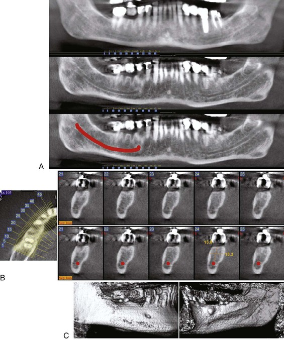
Figure 70-5 Cone-beam computed tomography (CBCT) images for the evaluation of the edentulous space at the area of missing tooth #30 before implant placement utilizing a large field-of-view FOV unit (NewTom 3G, Verona, Italy distributed by AFP Imaging, Elmsford, NY). Note the tooth-shaped marker used. A, Series of “panoramic” reconstructions through the alveolar ridge reveals the relationship of the marker to the adjacent teeth. The top “panoramic” view is 12 mm thick to depict most of the extent of the alveolar ridge and adjacent teeth. The middle “panoramic” image is 1 mm thick through the area of the mandibular canal. Note that adjacent teeth are out of the plane of the section and thus not depicted on the image. The bottom “panoramic” view is the same as the middle one, but the position of the mandibular canal has been depicted by the red line. B, Scout axial view and series of cross-sections through the area of the marker. The bottom row shows the same axial slices as the top row. However, the position of the red line drawn on the panoramic view is also depicted to help localization of the mandibular canal. The height and width of the alveolar ridge have been measured in a selected section. C, Three-dimensional reconstructions provide an overall impression of the bone contours and shape of the alveolar ridge. Note the small exostosis on the lingual surface of the alveolar ridge.
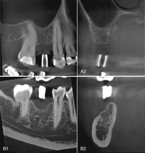
Figure 70-6 Cone-beam computed tomography (CBCT) images for the evaluation of the edentulous space at the area of missing tooth #4 (A) and missing tooth #30 (B) utilizing a small field-of-view (FOV) unit (Accuitomo 3D x-ray, J. Morita Corporation, Suita City, Osaka, Japan, distributed by J. Morita USA, Inc., Irvine, CA). Sagittal and cross-sectional slices are shown. Although the anatomic area imaged is limited, the resolution of the images are high. A, Implant site #4 (maxillary right second premolar) in anterior-posterior and buccal-lingual cross-sectional views. B, Implant site #30 (mandibular right first molar) in anterior-posterior and buccolingual cross-sectional views.
In general, CBCT offers the same advantages and disadvantages as CT. However, the two modalities have basic differences that result from the different physical principles used during image acquisition. CT scan offers a greater contrast resolution, or the ability to distinguish two objects with small density differences. CBCT scans have a limited capacity to separate muscle from fat or connective tissue compared with CT scans. Fortunately, contrast resolution is not a significant concern in implant evaluation. Because bone has a much higher density than surrounding soft tissues, both CBCT and CT can clearly depict bone shape and architecture. One of the most significant advantages of CBCT scanning versus CT scanning is the reduced amount of radiation dose delivered to the patient13,23 (see Table 70-2).
In summary, CBCT scanning is a valuable imaging modality for three-dimensional and cross-sectional evaluation of the implant patient. It has similar advantages and disadvantages as CT scanning. The most significant difference is that CBCT imaging delivers much less radiation exposure to the patient.
Interactive “Simulation” Software Programs
In many challenging cases, implant treatment planning can be greatly enhanced by the use of specialized software. These programs utilize data from the CT or CBCT scans and allow the simulation of implant placement and restoration on the computer. The quantity and quality of bone can be evaluated. A database of popular implant (commercial size and design) images is usually available to use with the three-dimensional images. The length, width, angulation, and position of implants can be “simulated” in the desired positions. In cases of alveolar ridge deficiency or defects or when sinus bone augmentation is indicated, the additional bone volume needed can be evaluated and quantified. The restoration of the implants can also be simulated and the distribution of mechanical forces onto the implant and adjacent bone predicted.
Software programs specialized in implant treatment planning, such as SIM/Plant (Materialise/Columbia Scientific, Glen Burnie, MD), can reformat CBCT or CT scan data. The clinician can use the reformatted images on a personal computer in an interactive manner to identify anatomic structures, simulate implant placement positions and better appreciate relationships between planned implant positions and teeth or anatomic structures (Figure 70-7).
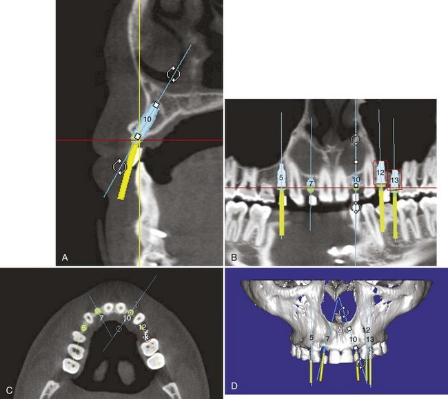
Figure 70-7 SIM/Plant images. The SIM/Plant software program allows clinicians to measure bone height, width, density, and volume on a personal computer. Scan data are reformatted for interactive evaluation and manipulation. Implant positions can be simulated on the patient’s scan data before surgery, allowing the surgeon to anticipate areas of deficiency.
Patient Evaluation
Evaluation of the implant patient should be disciplined and objective. Specific questions that can affect implant placement and outcome should be considered and examined carefully and explicitly. The advantages and disadvantages of various radiographic projections should be considered and radiographic modalities chosen based on necessary information for the particular patient. The objectives for any radiographic evaluation, regardless of imaging technique used, should include an evaluation to (1) exclude pathology, (2) identify anatomic structures, and (3) measure the quantity, quality, and location of available bone.
Exclude Pathology
Healthy bone is prerequisite for successful osseointegration and long-term implant success. The first step in the radiographic evaluation of the implant site is to establish the health of the alveolar bone and other tissues imaged within a particular projection. Local and systemic diseases that affect bone homeostasis can preclude, modify, or alter placement of implants. Retained root fragments, residual periodontal disease, cysts, and tumors should be identified and resolved before implant placement. Systemic diseases, such as osteoporosis and hyperparathyroidism, alter bone metabolism and might affect implant osseointegration. Areas of poor bone quality should be identified and if indicated, adjustments to the treatment plan incorporated. Maxillary sinusitis, polyps, or other sinus pathology should be diagnosed and treated when implants are considered in the posterior maxilla, especially if sinus bone augmentation procedures are planned (Figure 70-8).
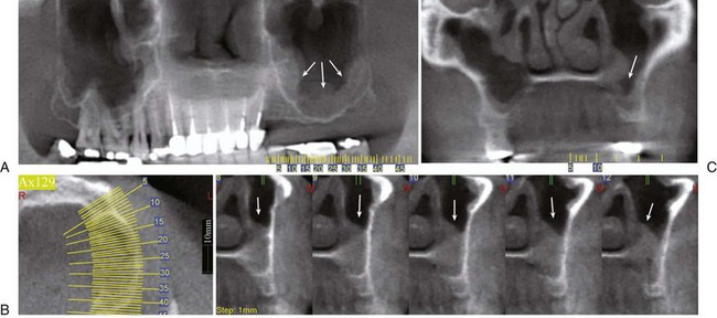
Figure 70-8 Cone-beam computed tomography (CBCT) examination of the posterior left maxilla. “Panoramic” (A), coronal (B), and axial and cross-sectional (C) views of the alveolar ridge. Note the thickened mucoperiosteal lining of the floor of the left maxillary sinus (white arrow). The patient has chronic maxillary sinusitis.
Identify Anatomic Structures
Several important anatomic structures are found close to desired areas of implant placement in the maxilla and mandible (Box 70-1). Familiarity with the radiographic appearance of these structures is important during treatment planning and implant placement. Their exact localization is central to prevent unwanted complication and unnecessary morbidity. Important anatomic structures in the maxilla include the floor and anterior wall of the maxillary sinus, incisive foramen, floor and lateral wall of the nasal cavity, and canine fossa. Important anatomic structures in the mandible that should be recognized include the mandibular canal, anterior loop of the mandibular canal, mental foramen, anterior extension of the canal, and submandibular fossa. The existence of anatomic variants, such as incomplete healing of an extraction site, sinus loculation, division of mandibular canal (Figure 70-9), or absence of a well-defined corticated canal, should also be recognized.
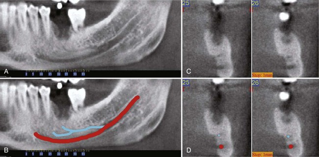
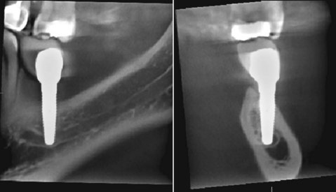
Figure 70-9 Cone-beam computed tomography (CBCT) examination of the area of missing tooth #19 before implant placement. A, Panoramic view of the area of interest depicts an accessory mandibular canal. B, Same panoramic view with the accessory mandibular canal colored blue and the main canal red. C, Cross-sectional views through the area of missing tooth #19. D, Same cross-sectional images depicting the blue and red markings. Note that the position of the markings coincides with the position of the accessory and main mandibular canals (compare C and D).
Assess Bone Quantity, Quality, and Volume
The primary goal of diagnostic imaging for potential implant patients is to evaluate the available bone volume for implant placement in desired anatomic locations. The clinician wants to estimate and verify exact adequate height, width, and density to the recipient bone while avoiding damage to critical anatomic structures. Failure to assess accurately the location of important anatomic structures can lead to unnecessary complications. For example, inadvertent penetration and damage to the inferior alveolar nerve can result in serious immediate-term (profuse bleeding), short-term, and long-term (nerve paresthesia/anesthesia) complications. The height and width of the alveolar bone should be accurately detailed. depending on the technique, diagnostic imaging can estimate or measure the coronal-apical height, the buccal-lingual width, and the mesial-distal spacing available for implants that will be placed in proximity to teeth or relative to other planned implants.
This task can be simple in cases with good bone quality and sufficient bone volume in the desired implant location(s). However, in cases with moderate-severe bone resorption, alveolar defects, or recent extraction sites, obtaining a clear and accurate diagnostic image can be more challenging. The diagnostic imaging may reveal inadequate bone volume for the proposed implant(s) and indicate a need for bone augmentation or depending on the severity of the deficiency, preclude the patient from the possibility of implant therapy (Figure 70-10).
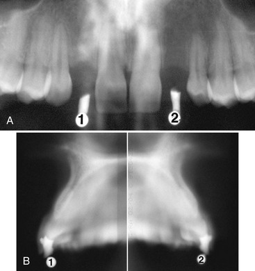
Figure 70-10 Radiographic evaluation of a patient with congenitally missing maxillary lateral incisors before implant placement. A, Panoramic radiograph reveals sufficient height and mesial-lateral width of the alveolar ridge. B, Cross-sectional conventional tomography of the edentulous areas reveals a narrow (<4 mm) buccal-lingual width of the alveolar ridge that needs to be addressed by modifications in the treatment planning, such as bone augmentation.
In addition to the amount, the quality of the available bone should also be evaluated. A uniform, continuous cortical outline and a lacy, well-defined trabecular core reflect the normal bone homeostasis necessary for appropriate bone response around the implant. Thin or discontinuous cortex, sparse trabeculation, large marrow spaces, and altered trabecular architecture should be noted because they might predict poor implant stabilization and less desirable response of the bone. Poor bone quality may necessitate modifications of the treatment planning, such as waiting longer for healing (osseointegration) to maximize bone-to-implant contact before loading.
Evaluate Relation of Alveolar Ridge with Existing Teeth and Desired Implant Position
Accurate placement (spatial position and angulation relative to adjacent teeth and occlusal plane) will greatly affect the restorative success and long-term prognosis of the implant (see Chapter 76). A significant variable during the preimplant evaluation is the relation of the desired implant position relative to the existing teeth, alveolar crest, and occlusal plane. Angled or custom abutments can accommodate slight variations in implant position and implant inclination. However, more significant deviations should be avoided.
Prolonged tooth loss is usually associated with atrophy of the alveolar ridge and in the case of the maxilla, with pneumatization of the sinus floor toward the alveolar crest. Traumatic extractions can compromise the buccal or lingual cortex and alter the shape and buccolingual ridge dimension. Anatomic variants, such as lingual inclination of the alveolus or narrow ridges, should be considered during treatment planning of the implant patient (Figure 70-11).
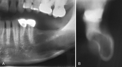
Figure 70-11 Radiographic evaluation of a patient with edentulous posterior left mandible before implant placement. A, Panoramic radiograph demonstrates sufficient height of the alveolar ridge with little or no resorption. B, Cross-sectional conventional tomography reveals significant lingual inclination of the alveolar ridge with lingual concavity that is not depicted on the panoramic radiograph.
An important part of diagnostic imaging must include an evaluation of the available bone relative to the “prosthetically driven” implant position. This aspect of the patient evaluation is best accomplished with diagnostic models, wax-up of planned tooth replacement, and radiographic markers in the desired tooth positions during imaging. Steel balls, brass tubes, and gutta percha have all been used to establish the proposed tooth positions relative to the existing alveolar bone. The use of these nonanatomic markers is helpful for evaluating bone height and width in specific anatomic locations. However, they do not accurately represent the tooth contours and do not allow the clinician to estimate variations in implant position and angulation relative to the position and emergence of the planned tooth replacement. Therefore, it is more desirable and beneficial to use radiopaque “tooth-shaped” markers so that the existing alveolar bone can be evaluated relative to the entire tooth position/contours (Figure 70-12; see also Figures 70-3 and 70-5). This is particularly important for anterior, esthetic implant cases. Patients should always be imaged with radiographic guides (markers).
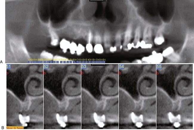
Figure 70-12 A, Panoramic view of partially edentulous maxilla with tooth shaped markers in areas of missing teeth (potential implant sites). B, Cross-sectional views from a cone-beam computed tomography (CBCT) examination before implant placement in the right maxilla. Appropriately sized and shaped tooth markers placed in the prosthetically desired locations of the planned restorations for the missing teeth help evaluate the existing alveolar ridge relative to the prospective tooth positions and contours.
Clinical Selection of Diagnostic Imaging
Radiography is an important diagnostic tool for the evaluation of the implant patient. However, radiographic imaging alone is not sufficient. It is important to correlate diagnostic information with a good clinical examination. Conversely, a clinical examination is insufficient to provide the information needed to plan implant treatment for a patient without some radiographic imaging.
Clinical Examination
Before taking any radiographs, a complete clinical examination of the implant patient is required. This should include the etiology and duration of tooth loss, any history of traumatic extraction, and a review of records and radiographs, if available. Clinical assessment of the edentulous area, covering mucosa, adjacent and opposing teeth, and occlusal plane should be performed. Temporomandibular function, mandibular maximal opening, and protrusive and lateral movements should be evaluated (see Chapter 69).
Screening Films
At this point, an overall assessment of the health of the jaws should be performed. Periapical films provide a high-resolution image of the alveolus and the surrounding structures, including adjacent teeth. For extended edentulous areas, panoramic, lateral cephalometric, and occlusal films can be used to estimate bone height and width. Any pathology of the bone at the prospective implant site, as well as of the surrounding structures, should be identified and treated as indicated.
Fabrication of Radiographic and Surgical Guides
Once the health of the soft and hard tissues is established, casts should be taken and detailed analysis performed. The clinician should decide on the number of implants and their desired location. Next, a radiographic guide should be fabricated, usually with clear acrylic. The position of the desired implants is indicated by the use of radiopaque objects such as metallic balls, cylinders, or rods; gutta percha; or composite resin. If CT imaging might be performed, the use of metallic markers should be avoided. The design of such a guide greatly enhances the diagnostic information provided by the radiographs because it correlates the radiographic anatomy with the exact position of the proposed implant location.
Cross-Sectional Tomography
Some type of cross-sectional imaging, such as conventional tomography, CT, or CBCT, should be performed before implant placement in any site of the jaws.21 Plain (two-dimensional) films might be sufficient in select implant cases. For example, a single anterior maxillary site with good interdental space and bone volume and no significant anatomic structures at risk might not require cross-sectional imaging. On the other hand, the potential morbidity of a compromised anatomic structure and the poor performance and potential failure of a misplaced implant, combined with the wide availability of tomographic facilities, favor the use of cross-sectional imaging in most cases of implant treatment planning. It is crucial that the cross sections are perpendicular to the curvature of the mandible and parallel to the planned implant. Improper patient positioning can lead to an overestimation of the height and width of the available bone. If the surgeon believes that sections were performed at the wrong angulation, new images should be requested. This might necessitate reexposure of the patient.
Intraoperative and Postoperative Radiographic Assessment
Various radiographic modalities can provide valuable information during implant placement. Because of the ease of acquisition and high resolution, periapical radiographs are most commonly used. Intraoperative radiographs can be taken during surgery to evaluate proximity to important anatomic structures. Sequential periapical films guide the clinician to visualize changes in direction and depth of the drilling procedure and parallelism to adjacent teeth and other implants (Figure 70-13). Digital radiographs are particularly advantageous during intraoperative assessment of implant placement; images appear on the screen almost instantaneously and can be manipulated to extract the most pertinent diagnostic information (see Chapter 31).
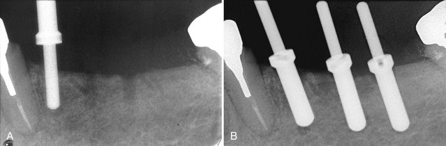
Figure 70-13 Intraoperative periapical radiographs are valuable in assessing the proximity of adjacent teeth. A, The 2-mm guide pin is used to determine direction of the osteotomy site and its proximity to the adjacent root. B, After angle correction, the osteotomy sites are completed to length with the final drill. Here the 3-mm guide pins confirm the correct angulation and spacing of the final osteotomy site preparation before implant placement.
Implant osseointegration and the level of periimplant alveolar bone are major determinants of implant prognosis. Panoramic and periapical radiographs offer a fast, easy, and low-radiation depiction of the implant and surrounding tissues and aid in assessment of implant success. To obtain an accurate assessment of periimplant bone height, the x-ray beam should be directed perpendicular to the implant. In the case of threaded implants, the implant threads should be distinguishable and not overlapping (Figure 70-14, A).
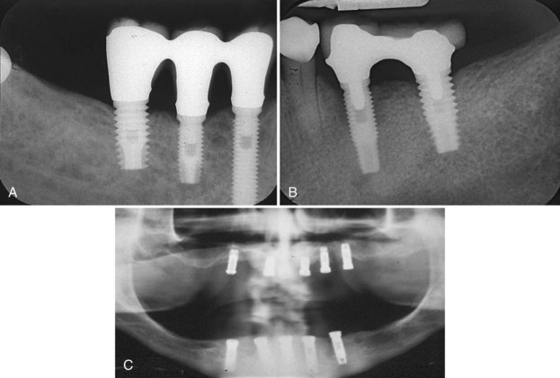
Figure 70-14 Radiographic follow-up after implant placement in three different patients. A, Periapical radiograph of three implants in the posterior right mandible. “Normal” bone remodeling around anterior two implants and slight horizontal bone loss/remodeling around the molar/posterior implant is present. B, Periapical radiograph of two implants in the left posterior mandible. Severe bone loss (50% of implant length) is seen around anterior implant, while mild bone loss/bone remodeling is observed around posterior implant. A moderate buccal cantilever in the restoration likely contributed to an adverse occlusal load and the resultant bone loss observed in this case. C, Panoramic radiograph of maxillary and mandibular implants in an edentulous patient prior to implant loading. The mandibular implants do not show signs of bone loss and appear to be osseointegrated. All maxillary show signs of moderate-to-severe periimplant bone loss and the success of osseointegration is questionable.
A 1.2-mm marginal bone loss during the first year after implant placement, and 0.1 mm per year afterwards is expected, while further bone loss is considered abnormal.2 Pathologic bone loss could be localized along the full extend of the implant (perifixtural bone loss) or around the crestal part of the implant (“saucerization”) and could reflect poor osseointegration, periimplantitis and/or unfavorable stress distribution (Figure 70-14, B and C).
In select cases, when poor implant placement (Figure 70-15) or compromise of vital anatomic structures (Figure 70-16) are suspected, advanced imaging (CBCT, CT, or conventional tomography) provides a three-dimensional evaluation of the oral structures in relation to the implants. Such information can be very important for proper assessment and treatment planning. The treating dentist should recognize relevant signs and symptoms and order appropriate imaging as soon after implant placement as possible. Implant removal, if necessary, would be less complicated before advanced osseointegration.
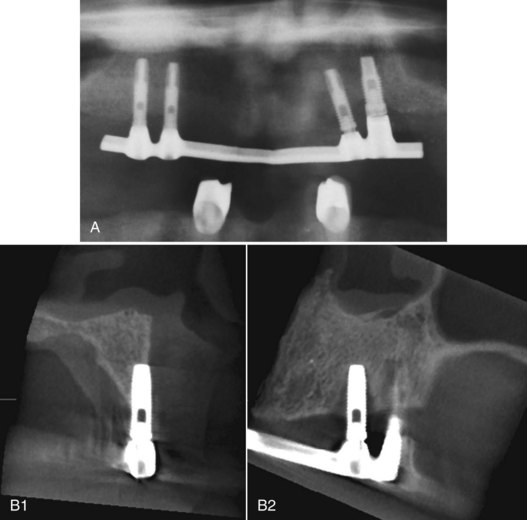
Figure 70-15 Radiographic follow-up after implant placement. A, Panoramic radiograph suggests mild-to-moderate bone loss around the neck of all implants. This is especially true for the implants in the left maxilla. These implants appear to be angled and the distal implant is positioned more apical. The overdenture bar is not completely seated on the left implants. Note superimposed overlapping anatomic structures in this panoramic radiograph impair the ability to clearly visualize and assess bone loss around implants. B, Cross-sectional and sagittal cone-beam computed tomography (CBCT) images of the anterior implant in the left maxilla. Poor implant placement beyond the buccal cortex of the alveolar ridge (cross-section) and periimplant bone loss (sagittal) are revealed.
Conclusion
Many radiographic projections are available for the evaluation of implant placement, each with advantages and disadvantages. The clinician must follow sequential steps in patient evaluation, and radiography is an essential diagnostic tool for implant design and successful treatment of the implant patient. Selection of appropriate radiographic modalities will provide the maximum diagnostic information, help avoid unwanted complications, and maximize treatment outcomes while delivering “as low as reasonably achievable” (ALARA) radiation dose to the patient.15
 Science Transfer
The use of three-dimensional radiographic diagnostics is necessary for almost every patient requiring dental implants. These techniques, combined with a diagnostic splint utilized at the time of the radiographs and at surgery, enables the clinician to assess the exact dimension of the needed implants and to precisely place implants in the correct location with the proper angulation.
At present, cone-beam computed tomography (CBCT) is the ideal method for obtaining diagnostic data. It provides precise measurement of bone dimensions in three planes and has significantly less radiation exposure than conventional CT scans.
Interactive simulation software programs are useful for complex cases because they allow the clinician to simulate a variety of implant sizes and placement techniques so that the most appropriate placement can be selected. A further application of three-dimensional digitized data is that is allows the clinician to have a surgical guide and a final prosthesis developed using computer-aided design/computer-aided manufacturing (CAD/CAM) technology. These approaches require a sophisticated surgical technique and may need further refinement to ensure the proper fit of the prosthesis.
Panoramic radiographs may be valuable as screening views but are not accurate enough for the precise measurements required for implant surgery. Periapical radiographs are a useful adjunct to CBCTs because they help more clearly visualize retained roots and other intrabony pathologic lesions.
1 Arai Y, Tammisalo E, Iwai K, et al. Development of compact computed tomographic apparatus for dental use. Dentomaxillofac Radiol. 1999;28:245.
2 Benson BW, Shetty V. Dental Implants. In White SC, Pharoah MJ, editors: Oral radiology: principles and interpretation, ed 6, St Louis: Mosby, 2009.
3 Cavalcanti MG, Yang J, Ruprecht A, et al. Validation of spiral computed tomography for dental implants. Dentomaxillofac Radiol. 1998;27:329.
4 Curry TS, Dowdey JE, Murry RC. Christensen’s physics of diagnostic radiology, ed 4. Philadelphia: Lea & Febiger; 1990.
5 Ekkestubbe A, Grondahl K, Grondahl HG. The use of tomography for dental implant planning. Dentomaxillofac Radiol. 1997;26:206.
6 Hatcher DC, Dial C, Mayorga C. Cone beam CT for pre-surgical assessment of implant sites. J Calif Dent Assoc. 2003;31:824.
7 Kassebaum DK, Nummikoski PV, Triplett RG, et al. Cross-sectional radiography for implant site assessment. Oral Surg Oral Med Oral Pathol. 1990;70:674.
8 Kraut RA. Utilization of 3D/dental software for precise implant site selection: clinical reports. Implant Dent. 1992;1:134.
9 Langland OE, Langlais RP, Preece JW, Panoramic and special imaging techniques,, Principles of dental imaging, ed 2, 2002, Lippincott Williams & Wilkins, Baltimore
10 Lindh C, Petersson A. Radiologic examination for location of the mandibular canal: a comparison between panoramic radiography and conventional tomography. Int J Oral Maxillofac Implants. 1989;4:249.
11 Lindh C, Petersson A, Klinge B. Measurements of distances related to the mandibular canal in radiographs. Clin Oral Implant Res. 1995;6:96.
12 Ludlow JB, Davies-Ludlow LE, White SC. Patient risk related to common dental radiographic examinations: The impact of 2007 International Commission on Radiological Protection recommendations regarding dose calculation. J Am Dent Assoc. 2008;139:1237.
13 Ludlow JB, Ivanonic M. Comparative dosimetry of dental CBCT devices and 64-slice CT for oral and maxillofacial radiology. Oral Surg Oral Med Oral Pathol Oral Radiol Endod. 2008;106:106.
14 Lurie AG. Panoramic imaging. In White SC, Pharoah MJ, editors: Oral radiology: principles and interpretation, ed 6, St Louis: Mosby, 2009.
15 Michel R, Zimmerman TL. Basic radiation protection considerations in dental practice. Health Phys. 1999;77:S81.
16 Mozzo P, Procacci C, Tacconi A, et al. A new volumetric CT machine for dental imaging based on the cone-beam technique: preliminary results. Eur Radiol. 1998;8:1558.
17 Scaf G, Lurie AG, Mosier KM, et al. Dosimetry and cost of imaging osseointegrated implants with film-based and computed tomography. Oral Surg Oral Med Oral Pathol Oral Radiol Endod. 1997;83:41.
18 Schulze D, Heiland M, Blake F, et al. Evaluation of quality of reformatted images from two cone-beam computed tomographic systems. J Craniomaxillofac Surg. 2005;33:19.
19 Sewerin IP. Errors in radiographic assessment of marginal bone height around osseointegrated implants. Scand J Dent Res. 1990;98:428.
20 Truhlar RS, Morris HF, Ochi S. A review of panoramic radiography and its potential use in implant dentistry. Implant Dent. 1993;2:122.
21 Tyndall DA, Brooks SL. Selection criteria for dental implant site imaging: a position paper of the American Academy of Oral and Maxillofacial Radiology. Oral Surg Oral Med Oral Pathol Oral Radiol Endod. 2000;89:630.
22 Whaites E, Periapical radiography,, Essentials of dental radiography and radiology, ed 3, 2002, Churchill Livingstone, London
23 White SC, Pharoah MJ, Radiation Safety and Protection,, Oral radiology: principles and interpretation, ed 6, 2009, Mosby, St Louis
24 White SC, Pharoah MJ, Intraoral radiographic examinations,, Oral radiology: principles and interpretation, ed 6, 2009, Mosby, St Louis