10 THE PARTIAL VENEER CROWN, INLAY, AND ONLAY PREPARATIONS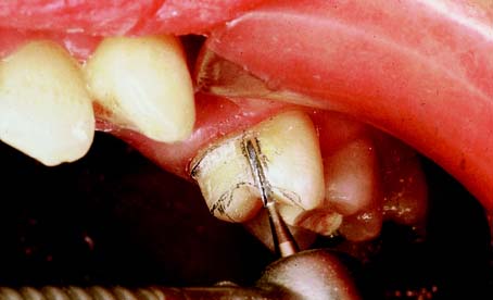
An extracoronal metal restoration that covers only part of the clinical crown is considered to be a partial veneer crown. It can also be referred to as a partial-coverage restoration. An intracoronal cast metal restoration is called an inlay or an onlay if one or more cusps are restored. Examples of these restorations are presented in Figure 10-1. Partial veneer crowns generally include all tooth surfaces except the buccal or labial wall in the preparation. Whenever feasible, a partial-coverage restoration should be selected, rather than a complete veneer, because it preserves more of the tooth’s coronal surface. However, the preparation is more demanding and is not routinely provided by practitioners. Buccolingual displacement of the restoration is prevented by internal features (e.g., proximal boxes and grooves). The partial veneer can be used as a single-tooth restoration, or it may serve as a retainer for a fixed dental prosthesis (FDP). It can be used on both anterior and posterior teeth. Because it does not cover the entire coronal surface, it tends to be less retentive than a complete crown and is less resistant to displacement. Unless the partial veneer is very carefully prepared, the reduced retention may contraindicate its use. Inlays and onlays are even less retentive than partial veneer crowns and are not recommended for FDP retainers. However, they provide the advantages of a casting, with less enamel removal than for a crown. When carefully prepared, they can produce an exceptionally long-lasting restoration.
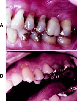
Fig. 10-1 A, Partial veneer crowns serving as retainers on the premolars for a four-unit fixed dental prosthesis replacing the maxillary first molar. B, Maxillary premolars restored with gold inlays, and molar restored with gold onlay. These restorations have served for about 35 years.
PARTIAL VENEER CROWNS
Several types of partial veneers exist: for posterior teeth, three-quarter, modified three-quarter, and seven-eighths crowns; for anterior teeth, three-quarter crowns and pinledges.
The indications, contraindications, advantages, and disadvantages of partial veneer crowns are described first, and any specific deviations that pertain to a given preparation are identified with that type.
Indications
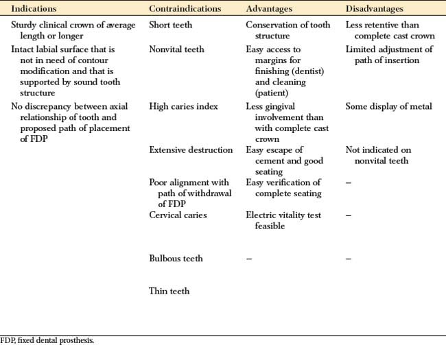
Partial veneer crowns often can be used to restore posterior teeth that have lost moderate amounts of tooth structure, if the buccal wall is intact and well supported by sound tooth structure. They are also commonly used as retainers for an FDP or where restoration or alteration of the occlusal surface is needed. Anterior partial veneers are rarely suitable for restoring damaged teeth, but they can be used as retainers, to reestablish anterior guidance, and to splint teeth. They are particularly suitable for teeth with sufficient bulk because they can accommodate the necessary retentive features.
Contraindications
Partial veneer restorations are contraindicated on teeth that have a short clinical crown because retention may not be adequate. They are also contraindicated as retainers for long-span FDPs. They are rarely suitable for endodontically treated teeth, especially anterior teeth, because insufficient supporting tooth structure remains for the retentive features. Likewise, they should not be used on endodontically treated posterior teeth if the buccal cusps are weakened by the access cavity or on teeth with an extensively damaged crown. As is true of all cast restorations, partial veneer restorations are contraindicated in dentitions with active caries or periodontal disease.
The shape and alignment of teeth are important determinants of the feasibility of partial veneer crowns. The alignment of axial surfaces should be evaluated, and partial veneer crowns should not be placed on teeth that are proximally bulbous. Making the necessary proximal grooves on these teeth is likely to leave unsupported enamel. It may be similarly impossible to prepare adequate grooves on thin teeth of restricted faciolingual dimension.
Partial veneer crowns are usually prepared parallel to the long axis of the tooth, and poorly aligned abutment teeth may not be suitable. When poorly aligned teeth are being prepared for a partial-coverage restoration, problems with unsupported enamel often result.
Advantages
The primary advantage associated with partial veneer crowns is conservation of tooth structure. Another advantage is reduced pulpal and periodontal insult during tooth preparation. Access to supragingival margins is rather easy and allows the operator to perform selected finishing procedures that are more difficult or impossible with complete coverage restorations. Access is also better for oral hygiene. Because less of the margin approximates the soft tissues subgingivally, there is less gingival involvement than with complete coverage.
During cementation of a partial veneer, the luting agent can escape more easily, which produces relatively good seating of the restoration. Because of direct visibility, verification of seating and cement removal are simple. When the restoration is in service, the remaining intact facial or buccal tooth structure permits electric vitality testing.
Disadvantages
Partial veneer restorations have less retention and resistance than do complete cast crowns. Preparing the tooth for this type of coverage is difficult, primarily because only limited adjustments can be made in the path of placement. The preparation of grooves, boxes, and pinholes requires dexterity of the operator. Some metal is displayed in the completed restoration, which may be unacceptable to patients with high cosmetic expectations.
Preparation
The following discussions cover the teeth most commonly prepared for partial veneer restorations. The use of partial veneers on anterior teeth has declined because of the difficulty in achieving an esthetic result. The technique illustrated may be suitable for posterior teeth and, with minimal variation, for other teeth. On both posterior and anterior teeth, meticulous care and precision are required if partial veneer restorations are to be a successful (conservative) alternative to complete-coverage restorations.
Armamentarium
The necessary instruments for a partial veneer crown preparation include the following (Fig. 10-2):
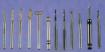
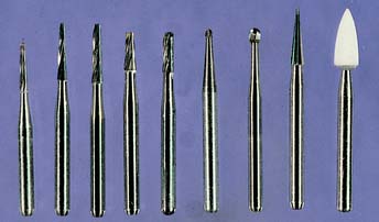
This is the typical armamentarium for a partial veneer crown preparation. Depending on operator preference, additional instruments can be used. The regular- or coarse-grit diamonds are used for bulk reduction, and the fine-grit diamonds or carbides are used for finishing. Pinholes are prepared with the twist drill and finalized with a tapered carbide. The fissure burs are recommended for preparing boxes and ledges, and the inverted-cone carbide is recommended for preparing incisal offsets. Hand instruments can be used to finish proximal flares and bevels. A periodontal probe is invaluable for assessing the direction and dimension of the various steps.
Posterior Partial Veneer Crown Preparations
Maxillary premolar three-quarter crown
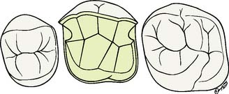
The three-quarter crown preparation (Fig. 10-3) derives its name from the number of axial walls involved. Except for a slight bevel or chamfer placed along the bucco-oclusal line angle, the buccal tooth surface remains intact. The other surfaces (including the occlusal surface) are prepared to accommodate a casting in the same manner as a complete crown preparation (see Chapter 8), differing only in the need for axial retention grooves.
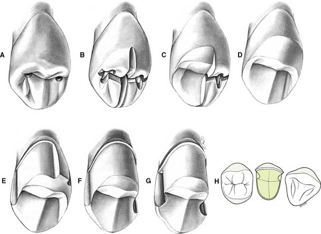
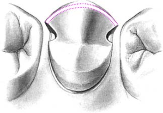
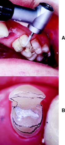
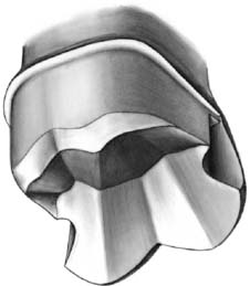
Fig. 10-3 The maxillary premolar three-quarter crown. A, Initial depth holes are placed in the mesial and distal fossae approximately 0.8 mm deep. B, They are connected by a guiding groove that extends through the central groove. Additional guiding grooves are placed on the lingual cusp similar to those for a complete cast crown (see Fig. 8-8). The depth cut placed on the triangular ridge of the buccal cusp becomes shallower as it approaches the cusp tip. C, Half the occlusal reduction is completed. Note the functional cusp bevel. The occlusocervical height of the buccal surface is not reduced at this stage. D, Occlusal reduction completed. E, After guiding grooves are placed in the lingual surface of the tooth parallel to the proposed path of placement, the proximoaxial and linguoaxial reductions are initiated. Simultaneously, a smooth and even-width cervical chamfer is created. F, When the axial reduction of the first half is considered acceptable, the other half can begin. G, Proximal grooves are placed perpendicular to the prepared surface, and the buccal wall of each groove is flared to leave no unsupported enamel. The proximal flares are connected with a narrow contrabevel. After rounding of the line angles, the preparation is complete. H, The interproximal clearance relative to adjacent teeth extends cervically as well as near the occlusal aspect of the buccal flares of the proximal grooves.
Occlusal reduction
Upon the completion of occlusal reduction, a clearance of at least 1.5 mm should exist on the functional cusp and at least 1.0 mm on the nonfunctional cusp and in the central groove. Simultaneously, the tooth should be prepared so that the restoration displays a minimum of metal, with preservation of the buccal wall outline.
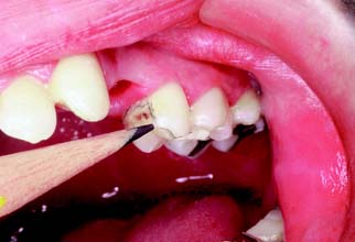
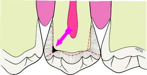
Fig. 10-5 A common error is insufficient reduction of tooth structure in the marginal ridge area (arrow).
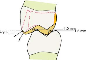
Fig. 10-6 Recommended minimum clearances for reduction of a partial veneer crown preparation. Slight hollow grinding of the lingual incline of the buccal cusp results in an acceptable clearance with the least display of metal. Also, the final restoration retains the normal contours of the cuspal ridge, so that incident light is not reflected and the restoration is less evident.
Axial reduction
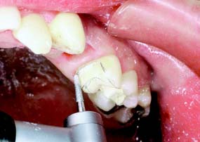
Fig. 10-7 Proximal and lingual axial reduction is performed with a round-tipped diamond. The proximal reduction is stopped short of the proposed location of the buccal margin.
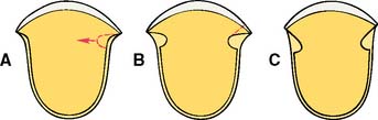
Fig. 10-8 A, Upon completion of the proximal axial reduction, a groove is placed perpendicular to the prepared surface. B, Note that some unsupported tooth structure remains at the cavosurface angle. C, After the buccal wall of the proximal groove is flared, no unsupported tooth structure remains. Note: It is important to anticipate in advance the influence of the buccal extent of the proximoaxial reduction (A) on the ultimate location of the margin (C).
Groove placement
Preparation of the proximal grooves is best done with a tapered carbide bur.
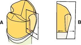
Fig. 10-10 Because of the rotary instrument’s taper, the proximal groove is deeper near the occlusal table (A). The floor of the groove should be flat and smooth. Often the proximal chamfer extends slightly cervically to the floor of the groove. If only minimal difference exists, as in B, the cervical margin adjacent to the groove can be beveled. The recommended occlusocervical height for a proximal groove is 4 mm.
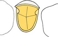
Fig. 10-11 The 90-degree angle between the lingual walls of the proximal grooves and the axial walls resists lingual displacement. Because the buccal aspect of the grooves has been adequately flared, no unsupported tooth structure remains.
Depending on available access, it may be feasible to complete the flaring with the same rotary instrument that was used to place the groove (Fig. 10-12). However, removing the last lip of unsupported tooth structure with a chisel is often a better option, because this minimizes the risk of damage to the adjacent tooth.
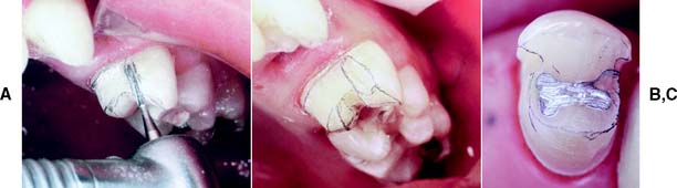
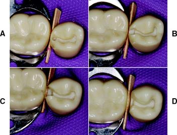
Fig. 10-12 A, Initial preparation of the mesial proximal groove. Note that the carbide is oriented parallel to the path of placement as dictated by the lingual surface of the tooth. B, Initial flaring has resulted in elimination of most unsupported tooth structure. C, Hand or rotary instruments are used to refine these proximal flares and remove all unsupported enamel.
Bucco-occlusal contrabevel
Occlusal offset
If additional bulk is needed to ensure rigidity of the restoration, it can be provided with an occlusal offset. This V-shaped groove extends from the proximal grooves along the buccal cusp. It is not usually necessary for posterior partial veneer crowns but is essential for the structural durability of anterior partial veneer crowns. This is described in detail on p. 301.
Finishing
Maxillary molar three-quarter crown
The principles used in a premolar preparation also apply for a maxillary molar (Figs. 10-15 and 10-16). However, some additional leeway may exist for groove placement because more tooth structure is present on molars than on premolars. Also, because of their less prominent position in the dental arch, molars are less visible. As a result, the mesioproximal flare can sometimes be extended onto the buccal surface without spoiling the esthetics.
Maxillary molar seven-eighths crown
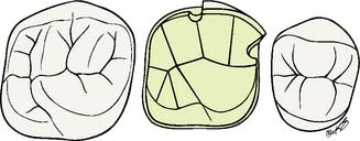
The seven-eighths crown preparation (Fig. 10-17) includes, in addition to the surfaces covered by the three-quarter crown, the distal half of the buccal surface. Therefore, the mesial aspect of this preparation resembles that for a three-quarter crown; the distal aspect resembles that for a complete crown. The mesial half of the buccal tooth surface remains intact and is protected by a narrow contrabevel or chamfer similar to the one used in the three-quarter crown preparation. A distal groove may be placed, although generally this is not necessary. A groove in the middle of the buccal surface is placed parallel to the path of placement. Distal to this groove, the buccal surface is reduced in two planes, cervical and occlusal; the cervical plane parallels the path of placement, and the occlusal plane follows the normal anatomic contour. The lingual surface of the tooth also is reduced in two planes, and functional cusp bevels are incorporated.
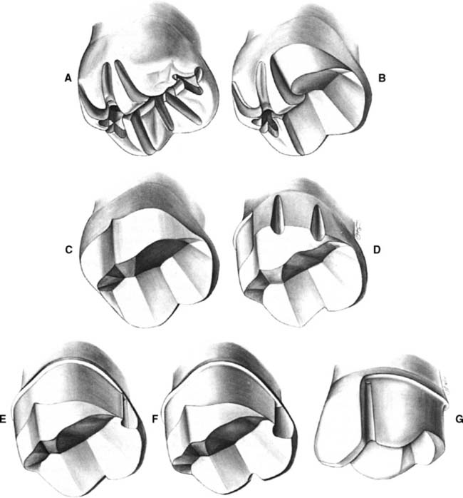
Fig. 10-17 The maxillary molar seven-eighths crown preparation. A, Occlusal depth grooves. On the lingual of the mesiobuccal cusp, they are identical to grooves for any functional cusp. On the buccal, note their difference from grooves placed on the triangular ridges. The mesial groove becomes shallower as it approaches the cuspal ridge; the distal extends through the cuspal ridge. B, Mesial half of the occlusal reduction is completed. Normal occlusal form can be recognized in the reduced area. C, Occlusal reduction completed. D, Distal half of the axial reduction completed. This is comparable to the preparation for a complete cast crown. The rotary instrument is moved parallel to the guiding grooves placed in the lingual tooth surface. E, Mesial half of the axial reduction completed and a proximal groove placed. F, The buccal groove, with flaring of the mesial groove. Note the monoplane of the flare, extending from the deepest portion of the groove to the cavosurface angle. G, A contrabevel connects the mesial flare with the buccal groove. The mesial wall of the buccal groove is smooth and has a 90-degree cavosurface angle, leaving no unsupported enamel.
Occlusal reduction
Upon completion of the occlusal reduction, adequate clearance should exist in all excursive movements of the mandible. Minimum measurements are the same as for the three-quarter crown preparation.
Axial reduction
In principle, the steps for axial reduction follow those for occlusal reduction.
Groove placement, flaring, and contrabevel
Mandibular premolar modified three-quarter crown
Mandibular partial veneer preparations (Fig. 10-20) are made more often on premolars than on molars. They differ from maxillary molar three-quarter crown preparations in two respects: (1) Additional retention is required because of the shorter crown lengths of mandibular teeth. This can be obtained by extending the preparation buccally, although because of their rather prominent position in the dental arch, these teeth should be modified only distal to their height of contour (Fig. 10-21). (2) The axial surface that is not prepared (the buccal) includes the functional cusp. This means that additional tooth structure must be removed to provide sufficient bulk of metal for strength.
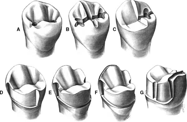
Fig. 10-20 The mandibular premolar modified three-quarter crown preparation. A, Depth holes placed in the mesial and distal fossae approximately 0.8 mm deep. B, The holes are connected by a guiding groove that extends through the central groove and the mesial and distal marginal ridges. Guiding grooves are also placed in the buccal and lingual triangular ridges, extending through the cuspal ridges on both sides. C, Half the occlusal reduction is completed. D, Occlusal reduction and mesial half of the axial reduction are completed. E, Axial reduction is completed. The proximal grooves have been placed. Note that the distal groove is close to the buccolingual center of the tooth. This enables retention of considerable tooth structure in the area of the distobuccal line angle, enhancing the resistance form of the preparation. F, The mesial groove has been flared and the functional cusp chamfer placed. G, Facial view. There is considerable width of the chamfer on the functional cusp. Note that the distobuccal cervical margin angles occlusally as it progresses mesially. This enables a more conservative tooth preparation in the area of the distobuccal modification that is placed to improve resistance form.
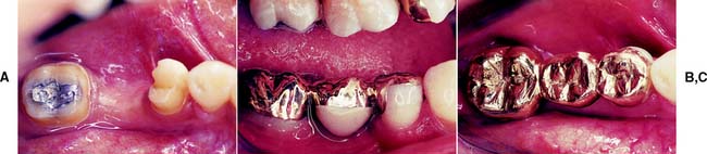
Fig. 10-21 Modified three-quarter crown restoring a mandibular second premolar. A, B, and C, The three-quarter crown is serving as the anterior retainer for a three-unit fixed dental prosthesis. Because the distobuccal modification remains in the distal fourth of the buccal preparation, it is hidden behind the normal height of contour of the buccal tooth surface. Note the considerable thickness of gold that protects the buccal cusp.
Occlusal reduction
Axial reduction
Finishing
The modified three-quarter crown preparation can include two or three grooves.
Anterior Partial Veneer Crown Preparations
As stated, with the advent of metal-ceramic restorations, the use of partial veneer restorations on anterior teeth has become rare. Nevertheless, two anterior partial veneer crown preparations, the maxillary canine three-quarter crown and the pinledge, are worthy of consideration (Figs. 10-22 and 10-23).
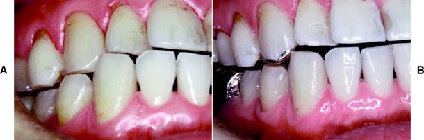
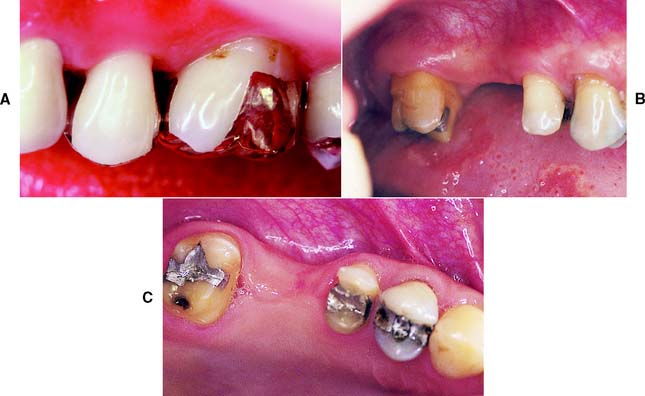
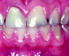
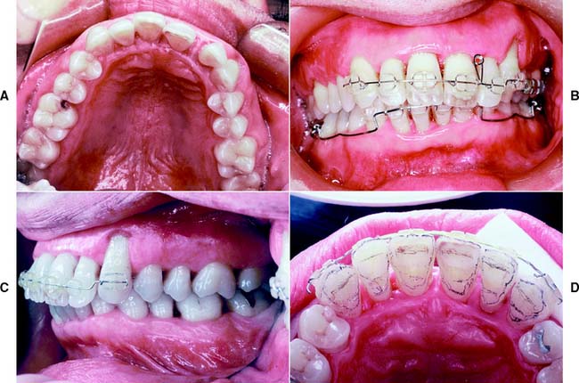
Fig. 10-22 A, Deficient anterior guidance resulting from years of parafunctional activity. B, An anterior partial veneer crown has reestablished guidance, allowing the intact sound labial tooth structure to be retained as a conservative alternative to a metal-ceramic restoration.
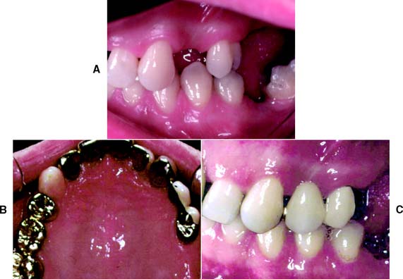
Fig. 10-23 A, Caries-free canine and lateral incisor of adequate bulk: excellent candidates for anterior partial veneer crowns. B, The canine restored with a three-quarter crown, serving as the anterior retainer for a three-unit fixed dental prosthesis (FDP) to replace the first premolar. The lateral incisor has been restored with a modified pinledge that serves as a retainer for an anterior four-unit FDP. C, Satisfactory esthetics with minimal display of metal are apparent.
Maxillary canine three-quarter crown
The three-quarter crown on a maxillary canine (Figs. 10-24 and 10-25) is probably one of the most demanding of all tooth preparations. As with such preparations on other teeth, on a maxillary canine it involves the proximal and lingual surfaces and leaves the facial surface intact. However, the greater degree of difficulty stems from the different shape of the canine tooth. Unless the placement of grooves is determined very precisely in advance, there is an undesirable display of metal in the interproximal embrasures (see Fig. 10-25A and B). The relatively short proximal walls do not allow much correction after initial groove placement. Similarly, the greater degree of curvature in each proximal wall immediately adjacent to the contact area significantly influences the location of the preparation’s facial margin.
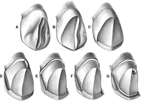
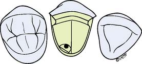
Fig. 10-24 The maxillary canine three-quarter crown preparation. A, A guiding groove is placed on the lingual surface. B, Half the lingual surface is reduced. Clearance is verified before reduction of the other half. C, Lingual reduction is completed, with an incisal bevel placed. No significant change has occurred in the incisocervical height. D, After an alignment groove is placed in the center of the cingulum wall, half the axial reduction is complete. Note that the path of placement parallels the incisal or middle third of the labial surface. As a result, the lingual chamfer is quite wide, perhaps even resembling a shoulder. This permits paralleling of the cingulum wall, with the proximal grooves and pinhole providing additional retention. E, Axial reduction is completed. Any final modification of the path of placement is done at this time before groove placement. F, Proximal grooves. The visible mesial groove has been flared, but unsupported enamel remains on both grooves where they meet the incisal bevel. G, Completed preparation. The lingual pinhole is surrounded by adequate dentin. Note the horizontal ledge prepared before pinhole placement.
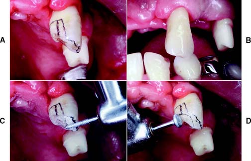
Fig. 10-25 A, Proposed margin location outlined on the tooth with a pencil. B, Careful assessment of the anticipated outline from as many directions as possible is valuable at this time. C, Preparing the incisal bevel. Typically a lingually tilted bevel is prepared at a 45-degree angle to the long axis of the tooth. D, The lingual surface is reduced with a wheel- or football-shaped diamond.
Incisal and lingual reduction
Axial reduction and groove placement
The path of placement of the restoration must be accurately determined before axial reduction. Mesiodistally, it should parallel the long axis of the tooth; buccolingually, it should parallel the middle third or incisal two thirds of the facial surface. This allows the preparation of proximal grooves of optimum length in an area of the tooth where sufficient bulk is present.
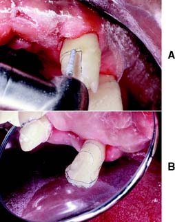
Fig. 10-26 A, A regular-grit diamond is used to complete the axial reduction. Mesiodistally, the diamond is oriented parallel to the long axis of the tooth. B, When the reduction is completed, a mesial and distal flange results; this serves as a guide during preparation of the proximal groove.
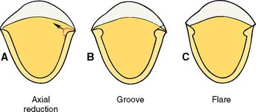
Fig. 10-27 A, Because the groove is prepared perpendicular to the proximal surface of the tooth, its deepest portion is slightly buccal to where axial reduction was halted. B, The dotted line indicates the proposed flare. Note that the curvature of the tooth causes the final margin to be located a considerable distance facial to where the initial axial reduction stopped. C, Completed flares.
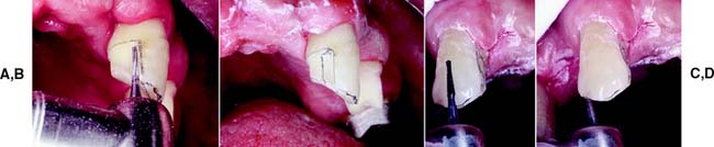
Fig. 10-28 A, A tapered carbide is used to place the proximal groove. B, Initial groove preparation is completed. C, The carbide is moved parallel to itself. D, Mesial and distal grooves must be prepared in strict alignment.
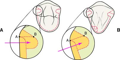
Fig. 10-29 Differences between the proximal flares on premolars and canines. A designates where the initial proximal reduction is halted. Because a facial component is present in the direction of groove placement on the canine, as opposed to the premolar, the starting point (B) for the flare is located farther to the facial aspect. In conjunction with the greater degree of proximal curvature of canines, it is crucial that the initial axial reduction not be carried too far facially; otherwise, the final margin will extend too far onto the labial surface of the tooth and result in excessive display of metal.
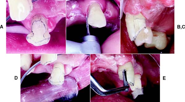
Fig. 10-30 A, Unsupported enamel remaining after initial groove placement. B, A carbide bur can be used to flare the grooves. C, The flared groove. Note the irregularity of the margin near the cervical aspect of the groove. D, After the flaring. Note that a mesial box, rather than a groove, has been prepared. This restoration is designed to contain an intracoronal partial removable dental prosthesis rest; hence, the box. Nevertheless, there is adequate resistance to lingual displacement. E, A special mandrel is placed in the box to ensure that it fits within its confines. It is identical in size to the male attachment of the partial removable dental prosthesis.
Incisal offset and lingual pinhole
Anterior partial veneer crowns require a means of reinforcement for preserving the casting’s integrity. Posterior three-quarter crowns usually do not need as much additional reinforcement because the solid “corrugated” occlusal surface provides rigidity. For an anterior tooth, an incisal offset or groove is needed to create a band of thicker metal to provide a “staple” configuration. This provides additional rigidity and resistance against bending of the casting.
Fig. 10-32 An inverted-cone diamond or carbide can be used to prepare the incisal offset. Note the faciolingual inclination of the rotary instrument.
The technical aspects of pinhole preparation are described in the ensuing paragraphs. The completed preparation (Fig. 10-33) is carefully assessed for any remaining undercuts. The flares are a common area for undercuts, and all surfaces should be smoothed as previously described.
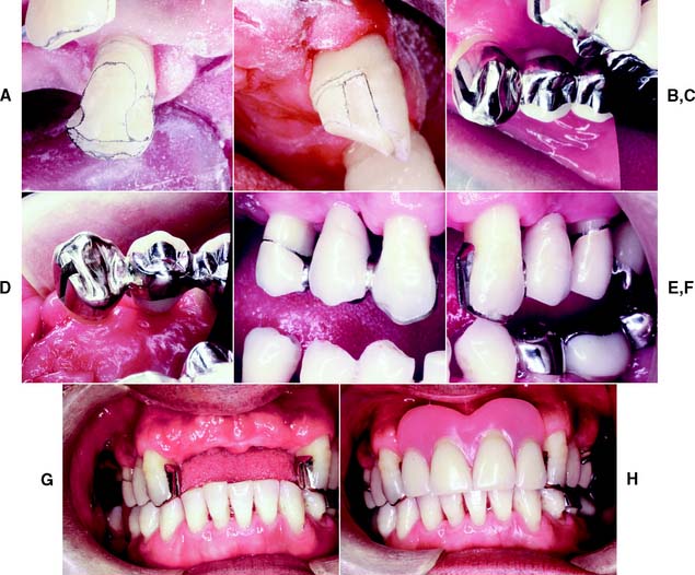
Fig. 10-33 A, Completed three-quarter crown preparation on a maxillary canine. B, The contralateral canine. C, A three-quarter crown serves as the anterior retainer for a three-unit fixed dental prosthesis (FDP); its female intracoronal rest is incorporated in the mesial box. D, Note the connector and the open embrasures on the contralateral side. E to G, Labial views of the cemented FDP. H, The definitive RDP.
Pinledge Preparations
A pinledge (Fig. 10-34) is occasionally used as a single restoration, generally to reestablish anterior guidance, in which case only the lingual surface is prepared. More commonly, however, it is used as a retainer for an FDP (Fig. 10-35) or to splint periodontally compromised teeth (Fig. 10-36). In these cases, one or more of the proximal surfaces are included in the preparation design to accommodate the required connector or connectors. Retention and resistance are provided primarily by pins that extend to a depth of 2 mm into dentin. In comparison with other retainers, the pinledge preparation is very conservative of tooth structure.
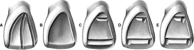
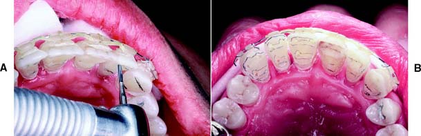
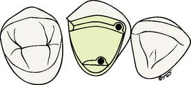
Fig. 10-34 The pinledge preparation on a maxillary central incisor. A, Guiding grooves placed for lingual reduction. B, The lingual reduction completed and an incisal bevel placed. C, Incisal and cervical ledges prepared. D, Indentations have been made. Note the spacing of the ledges in relation to each other and to the pulp. All pinholes will be in sound dentin. E, Pinholes prepared to a depth of 2 mm. The junction between the ledge and the pinholes has been countersunk.
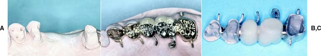
Fig. 10-35 A, Modified pinledge serving as a retainer for a four-unit fixed dental prosthesis (FDP). An additional pinhole was placed in the cingulum and in the cervical aspect of the proximal groove; in the latter instance, this was done because insufficient tooth structure remained to provide resistance against lingual displacement. B, The FDP on the definitive cast. C, A four-unit FDP consisting of a modified pinledge, two metal-ceramic pontics, and a metal-ceramic crown.
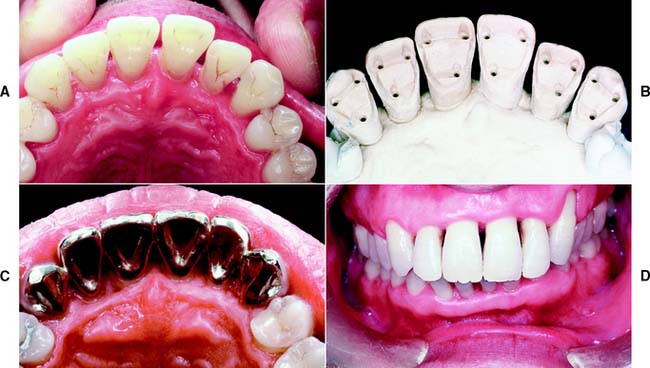
Fig. 10-36 A, Periodontally compromised but caries-free teeth of adequate buccolingual width are excellent candidates for a pinledge retained fixed splint. B, The definitive cast. C, Pinledge splint consisting of six separate castings that were soldered together and seated. D, A minimum display of metal results. The pinledge preparations allow retention of the intact labial enamel of all six anterior teeth.
The preparation steps themselves are not difficult, but advance planning and a thorough understanding of the various steps are prerequisites to success. Diagnostic preparation on an accurate cast is particularly useful during the planning phase. Preparation of a number of parallel pinholes with a common path of placement can be intimidating. With some practice, however, this can be accomplished freehand by most operators, especially when a tapered bur is used. Paralleling devices are available for practitioners who do not feel comfortable preparing multiple pinholes. In general, pinledges are highly esthetic restorations. Plaque control after treatment is easier because of short margin length and largely supragingival margin location.
Indications
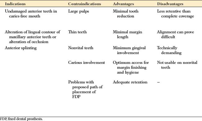
The pinledge is indicated for undamaged anterior teeth in dentitions with low caries activity. The presence of a small proximal carious lesion, however, does not preclude its use. If a high esthetic requirement exists, the advantage of this restoration is that the labial tooth surface remains intact, although this is sometimes offset by the display of a slight amount of metal along the incisal edge. Pinledges can be prepared on bulbous teeth that are unsuitable for three-quarter crowns, which would result in a significant amount of unsupported enamel interproximally. The lingual concavity of a maxillary anterior tooth can be modified successfully with a pinledge restoration (see Fig. 10-22) to establish the desired anterior guidance.
Contraindications
Patients with poor oral hygiene or a high caries rate are not good candidates for this type of restoration. Young patients with large pulps generally are better served by a resin-retained FDP (see Chapter 26). It is often not possible to place pinholes of adequate size and length in teeth that are thin labiolingually (Fig. 10-37). Pinledges are contraindicated on nonvital teeth and when the alignment of the abutment conflicts with the proposed path of placement of the FDP. Because less surface area is involved in the preparation, pinledges are not as retentive as their less conservative counterparts. Therefore, they should not be used when optimum retention is needed.
Maxillary central incisor pinledge
Three designs of pinledge preparations are discussed here: the conventional pinledge (see Fig. 10-34), involving only the lingual surface of the tooth; the pinledge with a proximal slice (Fig. 10-38); and the pinledge with a proximal groove (Fig. 10-39A). The latter two can serve equally well as retainers for an FDP; the choice of one over the other depends primarily on tooth configuration and the presence or absence of caries. A tooth with a slight proximal convexity can often be prepared successfully with a proximal slice, whereas one with a small carious lesion often lends itself better to the proximal groove variation. The pinledge preparation with proximal slice is described first.
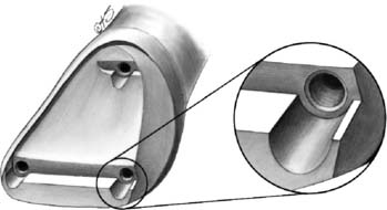
Fig. 10-38 Pinledge preparation with a proximal slice. The slice provides room for a fixed dental prosthesis connector. Sufficient tooth structure should remain between the slice and the pinhole adjacent to it. Note that the junction between pinhole and ledge has been beveled or countersunk.
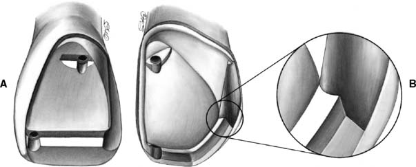
Fig. 10-39 A, Modified pinledge preparation with a proximal groove. The path of placement of this groove is compatible with the preparation as well as with the pinholes. B, A similar preparation on a maxillary canine. Note two similarities with the three-quarter crown: the heavy lingual chamfer and the incisal offset blending into the proximal groove to provide additional bulk for reinforcement.
Design
Proximal reduction
Incisal and lingual reduction
Ledges and indentations
Two ledges are prepared across the reduced lingual surface. They provide room for sufficient bulk of metal to ensure rigidity. The restoration would otherwise not be very strong because it would consist of only a thin sheet of metal.
The ledges are prepared parallel to the incisal edge of the tooth, as viewed from the lingual aspect, and parallel to one another, as viewed from the incisal aspect. In selected areas, they are widened to provide indentations of sufficient size to accommodate the pinholes. The determination of the incisocervical location of the ledges depends on the configuration of the pulp and the available bulk of tooth structure (Fig. 10-41). The incisal ledge is usually prepared 2 to 2.5 mm cervical to the incisal edge, or one fourth of the total height of the preparation from the incisal edge. The cervical ledge is placed on the crest of the cingulum at the center of the cervical one fourth of the preparation.
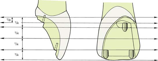
Fig. 10-41 Proximal lingual views of the location of ledges in relation to the height of the crown. The incisal ledge is placed so that its floor is one fourth of the preparation’s height from the incisal edge. The cervical ledge is placed so its floor bisects the cervical fourth. Note that the path of insertion is parallel to the incisal two thirds of the labial wall. Adequate offset of the cervical pinhole either mesially or distally is needed to prevent pulpal exposure.
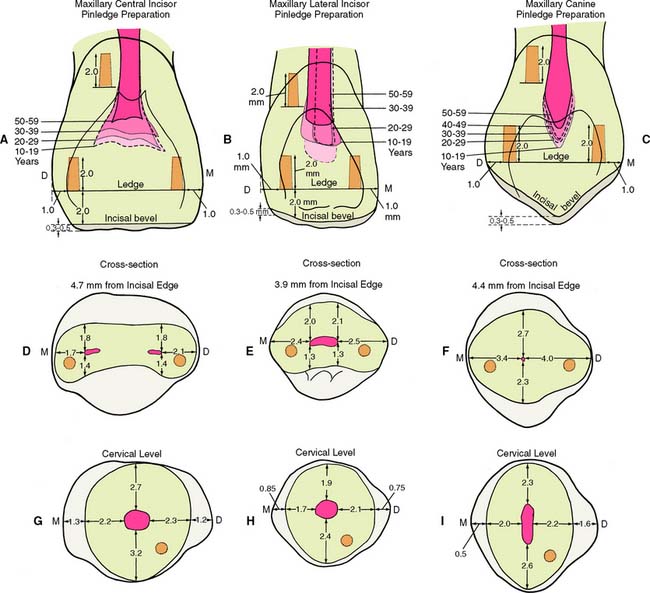
Fig. 10-42 Relationship between pinhole placement and pulp configuration. A to C, Lingual views. D to F, Cross-sections through incisal pinholes. G to I, Cross-sections through cervical pinholes. Dotted lines show the mean pulp chamber size of various age groups.
(Data from Ohashi Y: Shikagakuho 68:726, 1968.)
Pinhole preparation
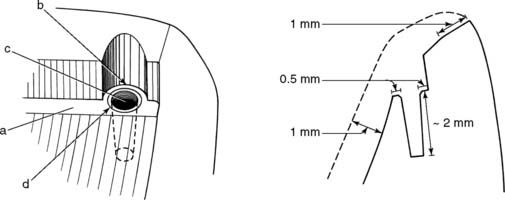
Fig. 10-44 Note the relation among the ledge, the indentation, and the pinhole. Recommended dimensions are given in the buccolingual cross section on the right. a, Ledge; b, indentation; c, pinhole; d, countersink.
INLAYS AND ONLAYS
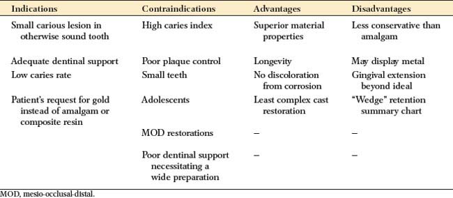
Indications
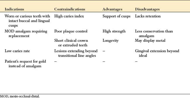
An inlay can be used instead of amalgam for patients with a low caries rate who require a small Class II restoration in a tooth with ample supporting dentin. It is among the least complicated cast restorations to make and can be very durable when it is carefully done. An onlay allows the damaged occlusal surface to be restored with a casting in the most conservative manner. It should be considered in the restoration of a severely worn dentition when the teeth are otherwise minimally damaged or for the replacement of a mesio-occlusal-distal (MOD) amalgam restoration when sufficient tooth structure remains for retention and resistance form.
Contraindications
Because these restorations rely on intracoronal (wedging) retention, inlays and onlays are contraindicated unless there is sufficient bulk to provide resistance and retention form. MOD inlays may increase the risk of cusp fracture and are generally not recommended. Extensive onlays, required where caries or existing restorations extend beyond the facial or lingual line angles, are contraindicated unless pins are used to supplement retention and resistance.
Advantages
Cast inlays and onlays can prove to be extremely long-lived restorations because of the excellent mechanical properties of the gold alloy. Low creep and corrosion mean that if inlay or onlay margins are accurately cast and finished, they will not deteriorate. The lack of corrosion may be an esthetic advantage. Gold does not lead to the tooth discoloration sometimes associated with dental amalgam. Unlike an inlay or amalgam, an onlay can support cusps, reducing the risk of tooth fracture.
Disadvantages
In the restoration of a small carious lesion, an inlay is not very conservative of tooth structure. This is because additional tooth removal is necessary after minimal proximal extension to achieve a cavity preparation without undercuts and to enable access for impression making. This extension may lead to additional display of metal and gingival encroachment, which is undesirable for periodontal health. Because they do not encircle the tooth, inlays rely on the bulk of the buccal and lingual cusps for resistance and retention form. There is concern that high occlusal force will lead to cusp fracture as a result of wedging from the inlay.
Preparation
Armamentarium
Carbide burs are usually used for inlay or onlay preparations (Fig. 10-47), but diamonds can be substituted if preferred:
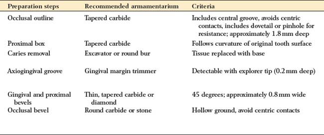
Class II Inlay Preparation (Fig. 10-48)
Occlusal analysis
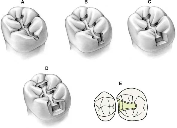
Fig. 10-48 The MO inlay preparation. A, An occlusal outline is prepared following the central groove and extended proximally. B, Gingival extension undermines the marginal ridge while removing caries. C, Unsupported enamel is removed, and the walls of the proximal box are defined. This is easily accomplished with hand instruments. D, An occlusal bevel or chamfer completes the preparation. E, Occlusal view of the completed preparation.
Outline form
Caries excavation
Axiogingival groove and bevel placement
Mesio-Occlusal-Distal Onlay Preparation
The occlusal outline and proximal boxes of an onlay preparation (Fig. 10-50) are similar to those of an inlay. The additional steps are the occlusal reduction and a functional (centric) cusp ledge.
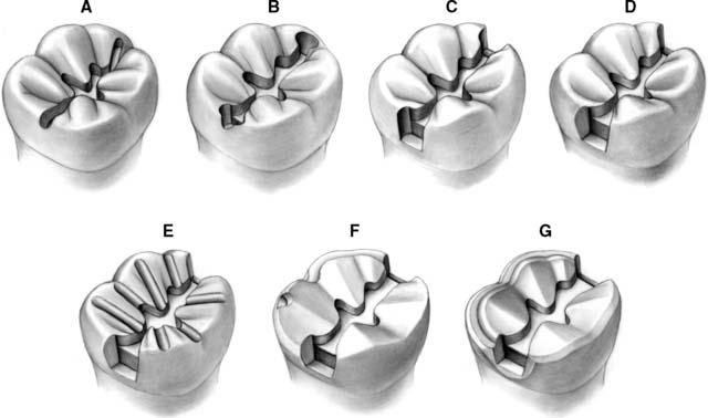
Fig. 10-50 The mesio-occlusal-distal (MOD) onlay preparation. A, An occlusal outline is prepared to follow the central fossa. B, The marginal ridges are undermined. C and D, The proximal boxes are refined. They should extend just beyond the proximal contact area. E, Depth grooves are placed for occlusal reduction: 0.8 mm on the nonfunctional cusp and 1.3 mm on the functional cusp. F, Note the buccal functional cusp bevel as part of the completed occlusal reduction. A buccal shoulder is prepared, approximately at the level of the pulpal floor. G, A continuous bevel completes the preparation. The bevel on the buccal shoulder makes a smooth transition into the proximal bevel of the box. A small contrabevel is placed on the lingual cavosurface margin.
Outline form
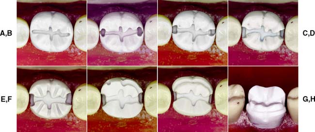
Fig. 10-51 Preparation of a mandibular molar tooth for a mesio-occlusal-distal (MOD) onlay. A, Preparation outline. B, Proximal boxes extended to remove contacts. C, Unsupported enamel removed with hand instruments. D, Proximal boxes are extended to form a 90-degree cavosurface angle. E, Occlusal reduction grooves. F, Functional cusp ledge placed for distal half. G and H, Completed preparation.
(Courtesy of Dr. H. Bowman.)
Occlusal reduction
Margin placement
SUMMARY CHART
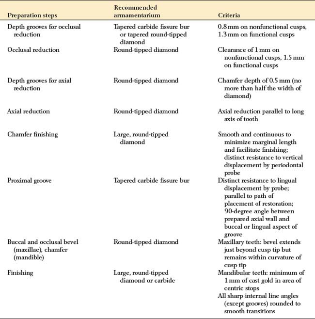
PARTIAL VENEER CROWN PREPARATION, POSTERIOR TEETH

| Preparation steps | Recommended armamentarium | Criteria |
|---|---|---|
| Depth grooves for occlusal reduction | Tapered carbide fissure bur or tapered round-tipped diamond | 0.8 mm on nonfunctional cusps, 1.3 mm on functional cusps |
| Occlusal reduction | Round-tipped diamond | Clearance of 1 mm on nonfunctional cusps, 1.5 mm on functional cusps |
| Depth grooves for axial reduction | Round-tipped diamond | Chamfer depth of 0.5 mm (no more than half the width of diamond) |
| Axial reduction | Round-tipped diamond | Axial reduction parallel to long axis of tooth |
| Chamfer finishing | Large, round-tipped diamond | Smooth and continuous to minimize marginal length and facilitate finishing; distinct resistance to vertical displacement by periodontal probe |
| Proximal groove | Tapered carbide fissure bur | Distinct resistance to lingual displacement by probe; parallel to path of placement of restoration; 90-degree angle between prepared axial wall and buccal or lingual aspect of groove |
| Buccal and occlusal bevel (maxillae), chamfer (mandible) | Round-tipped diamond | Maxillary teeth: bevel extends just beyond cusp tip but remains within curvature of cusp tip |
| Finishing | Large, round-tipped diamond or carbide | Mandibular teeth: minimum of 1 mm of cast gold in area of centric stops |
| All sharp internal line angles (except grooves) rounded to smooth transitions |
SUMMARY CHART
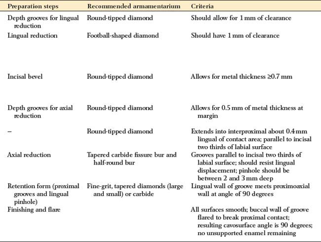
PARTIAL VENEER CROWN PREPARATION, ANTERIOR TEETH
| Preparation steps | Recommended armamentarium | Criteria |
|---|---|---|
| Depth grooves for lingual reduction | Round-tipped diamond | Should allow for 1 mm of clearance |
| Lingual reduction | Football-shaped diamond | Should have 1 mm of clearance |
| Incisal bevel | Round-tipped diamond | Allows for metal thickness =0.7 mm |
| Depth grooves for axial reduction | Round-tipped diamond | Allows for 0.5 mm of metal thickness at margin |
| — | Round-tipped diamond | Extends into interproximal about 0.4 mm lingual of contact area; parallel to incisal two thirds of labial surface |
| Axial reduction | Tapered carbide fissure bur and half-round bur | Grooves parallel to incisal two thirds of labial surface; should resist lingual displacement; pinhole should be between 2 and 3 mm deep |
| Retention form (proximal grooves and lingual pinhole) | Fine-grit, tapered diamonds (large and small) or carbide | Lingual wall of groove meets proximoaxial wall at angle of 90 degrees |
| Finishing and flare | All surfaces smooth; buccal wall of groove flared to break proximal contact; resulting cavosurface angle is 90 degrees; no unsupported enamel remaining |
SUMMARY CHART
CLASS II INLAY PREPARATION
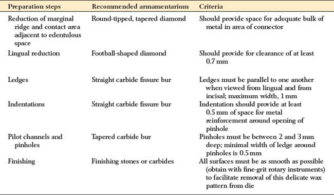
| Preparation steps | Recommended armamentarium | Criteria |
|---|---|---|
| Reduction of marginal ridge and contact area adjacent to edentulous space | Round-tipped, tapered diamond | Should provide space for adequate bulk of metal in area of connector |
| Lingual reduction | Football-shaped diamond | Should provide for clearance of at least 0.7 mm |
| Ledges | Straight carbide fissure bur | Ledges must be parallel to one another when viewed from lingual and from incisal; maximum width, 1 mm |
| Indentations | Straight carbide fissure bur | Indentation should provide at least 0.5 mm of space for metal reinforcement around opening of pinhole |
| Pilot channels and pinholes | Tapered carbide bur | Pinholes must be between 2 and 3 mm deep; minimal width of ledge around pinholes is 0.5 mm |
| Finishing | Finishing stones or carbides | All surfaces must be as smooth as possible (obtain with fine-grit rotary instruments) to facilitate removal of this delicate wax pattern from die |
| Preparation steps | Recommended armamentarium | Criteria |
|---|---|---|
| Occlusal outline | Tapered carbide | Includes central groove, avoids centric contacts, includes dovetail or pinhole for resistance; approximately 1.8 mm deep |
| Proximal box | Tapered carbide | Follows curvature of original tooth surface |
| Caries removal | Excavator or round bur | Tissue replaced with base |
| Axiogingival groove | Gingival margin trimmer | Detectable with explorer tip (0.2 mm deep) |
| Gingival and proximal bevels | Thin, tapered carbide or diamond | 45 degrees; approximately 0.8 mm wide |
| Occlusal bevel | Round carbide or stone | Hollow ground, avoid centric contacts |
SUMMARY CHART
MOD ONLAY PREPARATION
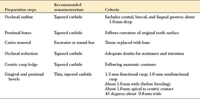
| Preparation steps | Recommended armamentarium | Criteria |
|---|---|---|
| Occlusal outline | Tapered carbide | Includes central, buccal, and lingual grooves; about 1.8 mm deep |
| Proximal boxes | Tapered carbide | Follows curvature of original tooth surface |
| Caries removal | Excavator or round bur | Tissue replaced with base |
| Occlusal reduction | Tapered carbide | Adequate dentin for resistance and retention |
| Centric cusp ledge | Tapered carbide | Following anatomic contours |
| Gingival and proximal bevels | Thin, tapered carbide | 1.5-mm functional cusp; 1.0-mm nonfunctional cusp |
| About 1.0 mm wide (before beveling) | ||
| About 1.0 mm apical to centric contact | ||
| 45 degrees; about 0.8 mm wide |