DIGESTIVE SYSTEM
Alimentary Canal
SUMMARY OF PROJECTIONS
Digestive System
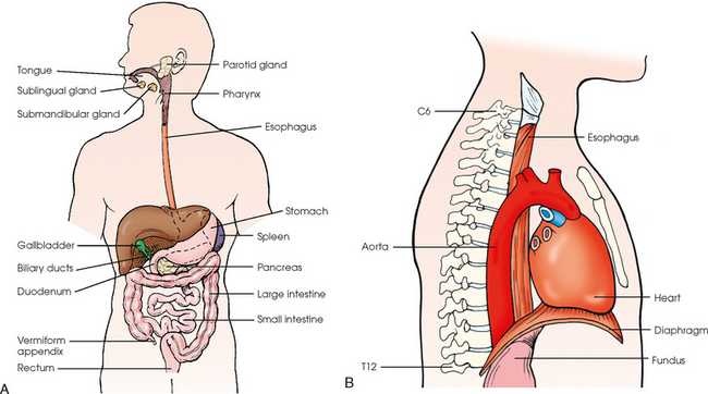
The digestive system consists of two parts: the accessory glands and the alimentary canal. The accessory glands, which include the salivary glands, liver, gallbladder, and pancreas, secrete digestive enzymes into the alimentary canal. The alimentary canal is a musculomembranous tube that extends from the mouth to the anus. The regions of the alimentary canal vary in diameter according to functional requirements. The greater part of the canal, which is about 29 to 30 ft (8.6 to 8.9 m) long, lies in the abdominal cavity. The component parts of the alimentary canal (Fig. 17-1) are the mouth, in which food is masticated and converted into a bolus by insalivation; the pharynx and esophagus, which are the organs of swallowing; the stomach, in which the digestive process begins; the small intestine, in which the digestive process is completed; and the large intestine, which is an organ of egestion and water absorption that terminates at the anus.
Esophagus
The esophagus is a long, muscular tube that carries food and saliva from the laryngopharynx to the stomach (see Fig. 17-1). The adult esophagus is approximately 10 inches (24 cm) long and ¾ inch (1.9 cm) in diameter. Similar to the rest of the alimentary canal, the esophagus has a wall composed of four layers. Beginning with the outermost layer and moving in, the layers are as follows:
The esophagus lies in the midsagittal plane. It originates at the level of the sixth cervical vertebra, or the upper margin of the thyroid cartilage. The esophagus enters the thorax from the superior portion of the neck. In the thorax, the esophagus passes through the mediastinum, anterior to the vertebral bodies and posterior to the trachea and heart (see Fig. 17-1, B). In the lower thorax, the esophagus passes through the diaphragm at T10. Inferior to the diaphragm, the esophagus curves sharply left, increases in diameter, and joins the stomach at the esophagogastric junction, which is at the level of the xiphoid tip (T11). The expanded portion of the terminal esophagus, which lies in the abdomen, is called the cardiac antrum.
Stomach
The stomach is the dilated, saclike portion of the digestive tract extending between the esophagus and the small intestine (Fig. 17-2). Its wall is composed of the same four layers as the esophagus.
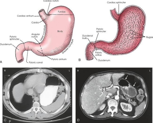
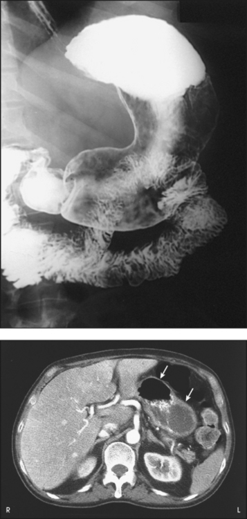
Fig. 17-2 A, Anterior surface of stomach. B, Interior view. C, Axial CT image of upper abdomen showing position of stomach in relation to surrounding organs. Note contrast media (white) and air (black) in stomach. D, Axial CT image showing stomach without contrast media. Note air (upper arrow) and empty stomach (lower arrow). (D, Modified from Kelley LL, Petersen CM: Sectional anatomy for imaging professionals, ed 2, St Louis, 2007, Mosby.)
The stomach is divided into the following four parts:
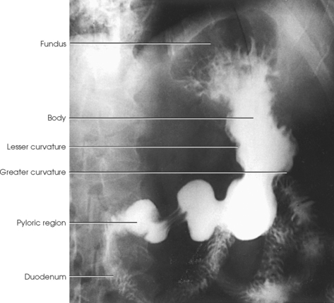
The cardia of the stomach is the section immediately surrounding the esophageal opening. The fundus is the superior portion of the stomach that expands superiorly and fills the dome of the left hemidiaphragm. When the patient is in the upright position, the fundus is usually filled with gas and in radiography is referred to as the gas bubble. Descending from the fundus and beginning at the level of the cardiac notch is the body of the stomach. The inner mucosal layer of the body of the stomach contains numerous longitudinal folds called rugae. When the stomach is full, the rugae are smooth. The body of the stomach ends at a vertical plane passing through the angular notch. Distal to this plane is the pyloric portion of the stomach, which consists of the pyloric antrum, to the immediate right of the angular notch, and the narrow pyloric canal communicating with the duodenal bulb.
The stomach has anterior and posterior surfaces. The right border of the stomach is marked by the lesser curvature. The lesser curvature begins at the esophagogastric junction, is continuous with the right border of the esophagus, and is a concave curve ending at the pylorus. The left and inferior borders of the stomach are marked by the greater curvature. The greater curvature begins at the sharp angle at the esophagogastric junction, the cardiac notch, and follows the superior curvature of the fundus and then the convex curvature of the body down to the pylorus. The greater curvature is four to five times longer than the lesser curvature.
The entrance to and the exit from the stomach are each controlled by a muscle sphincter. The esophagus joins the stomach at the esophagogastric junction through an opening termed the cardiac orifice. The muscle controlling the cardiac orifice is called the cardiac sphincter. The opening between the stomach and the small intestine is the pyloric orifice, and the muscle controlling the pyloric orifice is called the pyloric sphincter.
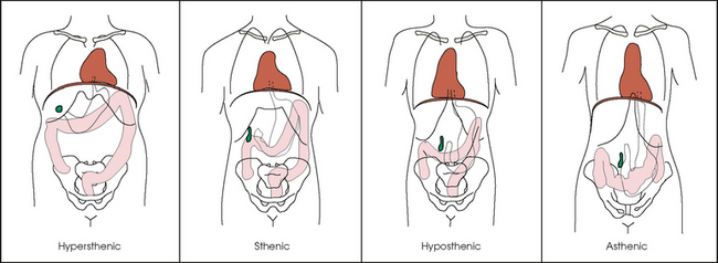
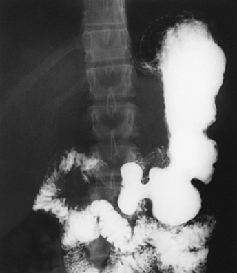
The size, shape, and position of the stomach depend on body habitus and vary with posture and the amount of stomach contents (Fig. 17-3). In persons with a hypersthenic habitus, the stomach is almost horizontal and is high, with its most dependent portion well above the umbilicus. In persons with an asthenic habitus, the stomach is vertical and occupies a low position, with its most dependent portion extending well below the transpyloric, or interspinous, line. Between these two extremes are the intermediate types of bodily habitus with corresponding variations in the shape and position of the stomach. The habitus of 85% of the population is either sthenic or hyposthenic. Radiographers should become familiar with the various positions of the stomach in the different types of body habitus so that accurate positioning of the stomach is ensured.
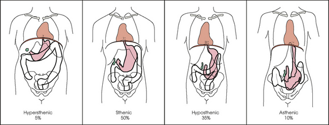
Fig. 17-3 Size, shape, and position of stomach and large intestine for the four different types of body habitus. Note extreme difference between the hypersthenic and asthenic types.
The stomach has several functions in the digestive process. The stomach serves as a storage area for food until it can be digested further. It is also where food is broken down. Acids, enzymes, and other chemicals are secreted to break food down chemically. Food is also mechanically broken down through churning and peristalsis. Food that has been mechanically and chemically altered in the stomach is transported to the duodenum as a material called chyme.
Small Intestine
The small intestine extends from the pyloric sphincter of the stomach to the ileocecal valve, where it joins the large intestine at a right angle. Digestion and absorption of food occur in this portion of the alimentary canal. The length of the adult small intestine averages about 22 ft (6.5 m), and its diameter gradually diminishes from approximately 1½ inches (3.8 cm) in the proximal part to approximately 1 inch (2.5 cm) in the distal part. The wall of the small intestine contains the same four layers as the walls of the esophagus and stomach. The mucosa of the small intestine contains a series of fingerlike projections called villi, which assist the process of digestion and absorption.
The small intestine is divided into the following three portions:
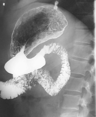
The duodenum is 8 to 10 inches (20 to 24 cm) long and is the widest portion of the small intestine (Fig. 17-4). It is retroperitoneal and relatively fixed in position. Beginning at the pylorus, the duodenum follows a C-shaped course. Its four regions are described as the first (superior), second (descending), third (horizontal or inferior), and fourth (ascending) portions. The segment of the first portion is called the duodenal bulb because of its radiographic appearance when it is filled with an opaque contrast medium. The second portion is about 3 or 4 inches (7.6 to 10 cm) long. This segment passes inferiorly along the head of the pancreas and in close relation to the undersurface of the liver. The common bile duct and the pancreatic duct usually unite to form the hepatopancreatic ampulla, which opens on the summit of the greater duodenal papilla in the duodenum. The third portion passes toward the left at a slight superior inclination for a distance of about 2½ inches (6 cm) and continues as the fourth portion on the left side of the vertebrae. This portion joins the jejunum at a sharp curve called the duodenojejunal flexure and is supported by the suspensory muscle of the duodenum (ligament of Treitz). The duodenal loop, which lies in the second portion, is the most fixed part of the small intestine and normally lies in the upper part of the umbilical region of the abdomen; however, its position varies with body habitus and with the amount of gastric and intestinal contents.
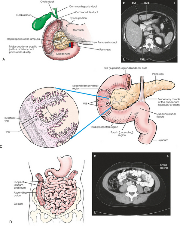
Fig. 17-4 A, Duodenal loop in relation to biliary and pancreatic ducts. B, CT axial image of pyloric antrum (pya), pyloric sphincter (pys), and duodenal bulb (duo). C, Anatomic areas of duodenum. Inset: Cross section of duodenum, showing villi. D, Loops of small intestine lying in central and lower abdominal cavity. E, CT axial image of small bowel loops with contrast media. (B and E, Modified from Kelley LL, Petersen CM: Sectional anatomy for imaging professionals, ed 2, St Louis, 2007, Mosby.)
The remainder of the small intestine is arbitrarily divided into two portions, with the upper two fifths referred to as the jejunum and the lower three fifths referred to as the ileum. The jejunum and ileum are gathered into freely movable loops, or gyri, and are attached to the posterior wall of the abdomen by the mesentery. The loops lie in the central and lower part of the abdominal cavity within the arch of the large intestine.
Large Intestine
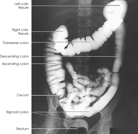
The large intestine begins in the right iliac region, where it joins the ileum of the small intestine, forms an arch surrounding the loops of the small intestine, and ends at the anus (Fig. 17-5). The large intestine has four main parts, as follows:
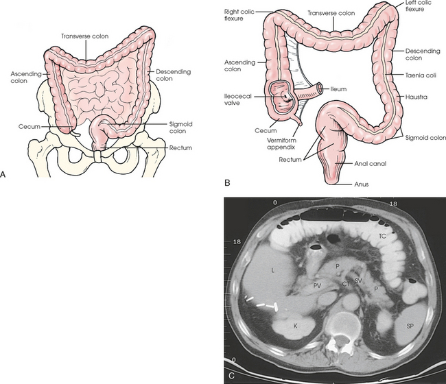
Fig. 17-5 A, Anterior aspect of large intestine positioned in abdomen. B, Anterior aspect of large intestine. C, Axial CT image of upper abdomen showing actual image of transverse colon positioned in anterior abdomen.
The large intestine is about 5 ft (1.5 m) long and is greater in diameter than the small intestine. The wall of the large intestine contains the same four layers as the walls of the esophagus, stomach, and small intestine. The muscular portion of the intestinal wall contains an external band of longitudinal muscle that forms into three thickened bands called taeniae coli. One band is positioned anteriorly, and two are positioned posteriorly. These bands create a pulling muscle tone that forms a series of pouches called the haustra. The main functions of the large intestine are reabsorption of fluids and elimination of waste products.
The cecum is the pouchlike portion of the large intestine and is below the junction of the ileum and the colon. The cecum is approximately 2½ inches (6 cm) long and 3 inches (7.6 cm) in diameter. The vermiform appendix is attached to the posteromedial side of the cecum. The appendix is a narrow, wormlike tube that is about 3 inches (7.6 cm) long. The ileocecal valve is just below the junction of the ascending colon and the cecum. The valve projects into the lumen of the cecum and guards the opening between the ileum and the cecum.
The colon is subdivided into ascending, transverse, descending, and sigmoid portions. The ascending colon passes superiorly from its junction with the cecum to the undersurface of the liver, where it joins the transverse portion at an angle called the right colic flexure (formerly hepatic flexure). The transverse colon, which is the longest and most movable part of the colon, crosses the abdomen to the undersurface of the spleen. The transverse portion makes a sharp curve, called the left colic flexure (formerly splenic flexure), and ends in the descending portion. The descending colon passes inferiorly and medially to its junction with the sigmoid portion at the superior aperture of the lesser pelvis. The sigmoid colon curves to form an S-shaped loop and ends in the rectum at the level of the third sacral segment.
The rectum extends from the sigmoid colon to the anal canal. The anal canal terminates at the anus, which is the external aperture of the large intestine (Fig. 17-6). The rectum is approximately 6 inches (15 cm) long. The distal portion, which is about 1 inch (2.5 cm) long, is constricted to form the anal canal. Just above the anal canal is a dilation called the rectal ampulla. Following the sacrococcygeal curve, the rectum passes inferiorly and posteriorly to the level of the pelvic floor and bends sharply anteriorly and inferiorly into the anal canal, which extends to the anus. The rectum and anal canal have two AP curves; this fact must be remembered when an enema tube is inserted.
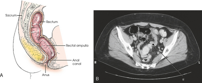
Fig. 17-6 A, Sagittal section showing direction of anal canal and rectum. B, Axial CT image of lower pelvis showing rectum and sigmoid colon (si) in relation to surrounding organs. (B, From Kelley LL, Petersen CM: Sectional anatomy for imaging professionals, ed 2, St Louis, 2007, Mosby.)
The size, shape, and position of the large intestine vary greatly, depending on body habitus (see Fig. 17-3). In hypersthenic patients, the large intestine is positioned around the periphery of the abdomen and may require more radiographs to show its entire length. The large intestine of asthenic patients, which is bunched together and positioned low in the abdomen, is at the other extreme.
Liver and Biliary System
The liver, the largest gland in the body, is an irregularly wedge-shaped gland. It is situated with its base on the right and its apex directed anteriorly and to the left (Fig. 17-7). The deepest point of the liver is the inferior aspect just above the right kidney. The diaphragmatic surface of the liver is convex and conforms to the undersurface of the diaphragm. The visceral surface is concave and molded over the viscera on which it rests. Almost all of the right hypochondrium and a large part of the epigastrium are occupied by the liver. The right portion extends inferiorly into the right lateral region as far as the fourth lumbar vertebra, and the left extremity extends across the left hypochondrium.
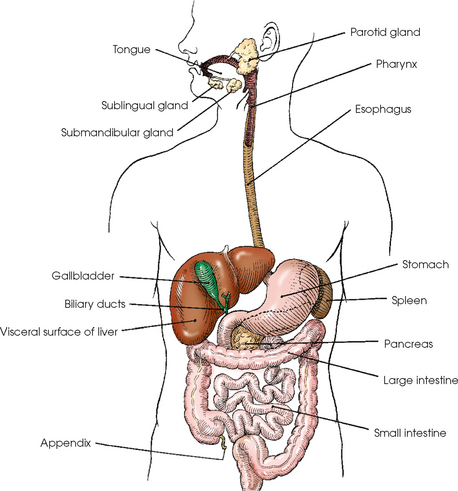
Fig. 17-7 Alimentary tract and accessory organs. To show position of gallbladder in relation to liver, the liver is shown with inferior portion pulled anteriorly and superiorly, placing the liver in an atypical position.
At the falciform ligament, the liver is divided into a large right lobe and a much smaller left lobe. Two minor lobes are located on the medial side of the right lobe: the caudate lobe on the posterior surface and the quadrate lobe on the inferior surface (Fig. 17-8, A). The hilum of the liver, called the porta hepatis, is situated transversely between the two minor lobes.
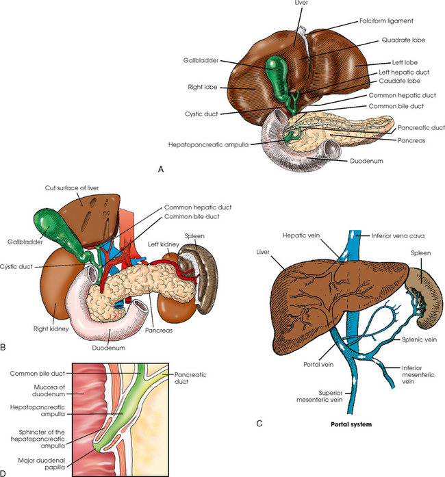
Fig. 17-8 A, Visceral surface (inferoposterior aspect) of liver and gallbladder. B, Visceral (inferoposterior) surface of gallbladder and bile ducts. C, Portal system showing hepatic artery and vein and other surrounding vessels. D, Detail of drainage system into duodenum.
The portal vein and the hepatic artery, both of which convey blood to the liver, enter the porta hepatis and branch out through the liver substance (see Fig. 17-8, C). The portal vein ends in the sinusoids, and the hepatic artery ends in capillaries that communicate with sinusoids. In addition to the usual arterial blood supply, the liver receives blood from the portal system.
The portal system, of which the portal vein is the main trunk, consists of the veins arising from the walls of the stomach, from the greater part of the intestinal tract and the gallbladder, and from the pancreas and the spleen. The blood circulating through these organs is rich in nutrients and is carried to the liver for modification before being returned to the heart. The hepatic veins convey the blood from the liver sinusoids to the inferior vena cava.
The liver has numerous physiologic functions. The primary consideration from the radiographic standpoint is the formation of bile. The gland secretes bile at the rate of 1 to 3 pints (½ to 1½ L) each day. Bile, the channel of elimination for the waste products of red blood cell destruction, is an excretion and a secretion. As a secretion, it is an important aid in the emulsification and assimilation of fats. The bile is collected from the liver cells by the ducts and either carried to the gallbladder for temporary storage or poured directly into the duodenum through the common bile duct.
The biliary, or excretory, system of the liver consists of the bile ducts and gallbladder (see Fig. 17-8). Beginning within the lobules as bile capillaries, the ducts unite to form larger and larger passages as they converge, finally forming two main ducts, one leading from each major lobe. The two main hepatic ducts emerge at the porta hepatis and join to form the common hepatic duct, which unites with the cystic duct to form the common bile duct. The hepatic and cystic ducts are each about 1½ inches (3.8 cm) in length. The common bile duct passes inferiorly for a distance of approximately 3 inches (7.6 cm). The common bile duct joins the pancreatic duct, and they enter together or side by side into an enlarged chamber known as the hepatopancreatic ampulla, or ampulla of Vater. The ampulla opens into the descending portion of the duodenum. The distal end of the common bile duct is controlled by the choledochal sphincter as it enters the duodenum. The hepatopancreatic ampulla is controlled by a circular muscle known as the sphincter of the hepatopancreatic ampulla, or sphincter of Oddi. During interdigestive periods, the sphincter remains in a contracted state, routing most of the bile into the gallbladder for concentration and temporary storage; during digestion, it relaxes to permit the bile to flow from the liver and gallbladder into the duodenum. The hepatopancreatic ampulla opens on an elevation on the duodenal mucosa known as the major duodenal papilla.
The gallbladder is a thin-walled, more or less pear-shaped, musculomembranous sac with a capacity of approximately 2 oz. The gallbladder concentrates bile by absorption of the water content; stores bile during interdigestive periods; and, by contraction of its musculature, evacuates the bile during digestion. The muscular contraction of the gallbladder is activated by a hormone called cholecystokinin. This hormone is secreted by the duodenal mucosa and released into the blood when fatty or acid chyme passes into the intestine. The gallbladder consists of a narrow neck that is continuous with the cystic duct; a body or main portion; and a fundus, which is its broad lower portion. The gallbladder is usually lodged in a fossa on the visceral (inferior) surface of the right lobe of the liver, where it lies in an oblique plane inferiorly and anteriorly. Measuring about 1 inch (2.5 cm) in width at its widest part and 3 to 4 inches (7.5 to 10 cm) long, the gallbladder extends from the lower right margin of the porta hepatis to a variable distance below the anterior border of the liver. The position of the gallbladder varies with body habitus, being high and well away from the midline in hypersthenic persons and low and near the spine in asthenic persons (Fig. 17-9). The gallbladder is sometimes embedded in the liver and frequently hangs free below the inferior margin of the liver.
Pancreas and Spleen
The pancreas is an elongated gland situated across the posterior abdominal wall. Extending from the duodenum to the spleen (Fig. 17-10; see Fig. 17-8), the pancreas is about 5½ inches (14 cm) long and consists of a head, neck, body, and tail. The head, which is the broadest portion of the organ, extends inferiorly and is enclosed within the curve of the duodenum at the level of the second or third lumbar vertebra. The body and tail of the pancreas pass transversely behind the stomach and in front of the left kidney, with the narrow tail terminating near the spleen. The pancreas cannot be seen on plain radiographic studies.
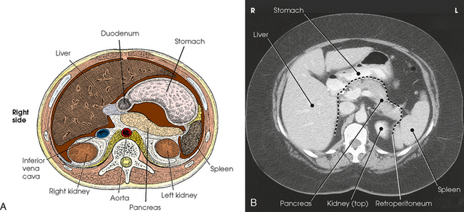
Fig. 17-10 A, Sectional image of upper abdomen (viewed from the patient’s feet upward), showing relationship of digestive system components. B, Axial CT image of same area of abdomen as in A. (B, From Kelley LL, Petersen CM: Sectional anatomy for imaging professionals, ed 2, St Louis, 2007, Mosby.)
The pancreas is an exocrine and an endocrine gland. The exocrine cells of the pancreas are arranged in lobules with a highly ramified duct system. This exocrine portion of the gland produces pancreatic juice, which acts on proteins, fats, and carbohydrates. The endocrine portion of the gland consists of clusters of islet cells, or islets of Langerhans, which are randomly distributed throughout the pancreas. Each islet comprises clusters of cells surrounding small groups of capillaries. These cells produce the hormones insulin and glucagon, which are responsible for glucose metabolism. The islet cells do not communicate directly with the ducts but release their secretions directly into the blood through a rich capillary network.
The digestive juice secreted by the exocrine cells of the pancreas is conveyed into the pancreatic duct and from there into the duodenum. The pancreatic duct often unites with the common bile duct to form a single passage via the hepatopancreatic ampulla, which opens directly into the descending duodenum.
The spleen is included in this section only because of its location; it belongs to the lymphatic system. The spleen is a glandlike but ductless organ that produces lymphocytes and stores and removes dead or dying red blood cells. The spleen is more or less bean-shaped and measures about 5 inches (13 cm) long, 3 inches (7.6 cm) wide, and 1½ inches (3.8 cm) thick. Situated obliquely in the left upper quadrant, the spleen is just below the diaphragm and behind the stomach. It is in contact with the abdominal wall laterally, with the left suprarenal gland and left kidney medially, and with the left colic flexure of the colon inferiorly. The spleen is visualized with and without contrast media.
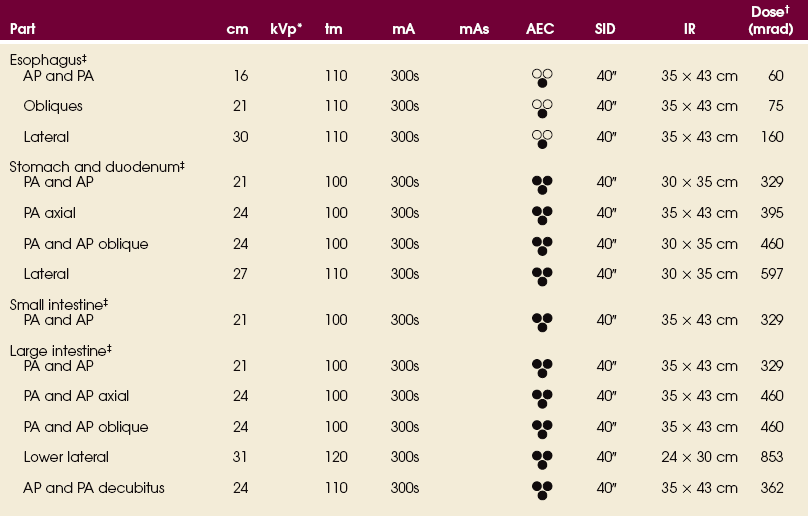
EXPOSURE TECHNIQUE CHART ESSENTIAL PROJECTIONS
SUMMARY OF PATHOLOGY
| Condition | Definition |
| Achalasia | Failure of smooth muscle of alimentary canal to relax |
| Appendicitis | Inflammation of the appendix |
| Barrett esophagus | Peptic ulcer of lower esophagus, often with stricture |
| Bezoar | Mass in the stomach formed by material that does not pass into the intestine |
| Biliary stenosis | Narrowing of bile ducts |
| Carcinoma | Malignant new growth composed of epithelial cells |
| Celiac disease or sprue | Malabsorption disease caused by mucosal defect in the jejunum |
| Cholecystitis | Acute or chronic inflammation of gallbladder |
| Choledocholithiasis | Calculus in common bile duct |
| Cholelithiasis | Presence of gallstones |
| Colitis | Inflammation of the colon |
| Diverticulitis | Inflammation of diverticula in the alimentary canal |
| Diverticulosis | Diverticula in the colon without inflammation or symptoms |
| Diverticulum | Pouch created by herniation of the mucous membrane through the muscular coat |
| Esophageal varices | Enlarged tortuous veins of lower esophagus, resulting from portal hypertension |
| Gastritis | Inflammation of lining of stomach |
| Gastroesophageal reflux | Backward flow of stomach contents into the esophagus |
| Hiatal hernia | Protrusion of the stomach through the esophageal hiatus of the diaphragm |
| Hirschsprung disease or congenital aganglionic megacolon | Absence of parasympathetic ganglia, usually in the distal colon, resulting in the absence of peristalsis |
| Ileus | Failure of bowel peristalsis |
| Inguinal hernia | Protrusion of the bowel into the groin |
| Intussusception | Prolapse of a portion of the bowel into the lumen of an adjacent part |
| Malabsorption syndrome | Disorder in which subnormal absorption of dietary constituents occurs |
| Meckel diverticulum | Diverticulum of the distal ileum, similar to the appendix |
| Pancreatitis | Acute or chronic inflammation of the pancreas |
| Pancreatic pseudocyst | Collection of debris, fluid, pancreatic enzymes, and blood as a complication of acute pancreatitis |
| Polyp | Growth or mass protruding from a mucous membrane |
| Pyloric stenosis | Narrowing of pyloric canal causing obstruction |
| Regional enteritis or Crohn disease | Inflammatory bowel disease, most commonly involving the distal ileum |
| Ulcer | Depressed lesion on the surface of the alimentary canal |
| Ulcerative colitis | Recurrent disorder causing inflammatory ulceration in the colon |
| Volvulus | Twisting of a bowel loop on itself |
| Zenker diverticulum | Diverticulum located just above the cardiac portion of the stomach |
Technical Considerations
Peristalsis is the term applied to the contraction waves by which the digestive tube propels its contents toward the rectum. Normally three or four waves per minute occur in the filled stomach. The waves begin in the upper part of the organ and travel toward the pylorus. The average emptying time of a normal stomach is 2 to 3 hours.
Peristaltic action in the intestines is greatest in the upper part of the canal and gradually decreases toward the lower portion. In addition to peristaltic waves, localized contractions occur in the duodenum and the jejunum. These contractions usually occur at intervals of 3 to 4 seconds during digestion. The first part of a “barium meal” normally reaches the ileocecal valve in 2 to 3 hours, and the last portion reaches the ileocecal valve in 4 to 5 hours. The barium usually reaches the rectum within 24 hours.
The specialized procedures commonly used in radiologic examinations of the esophagus, stomach, and intestines are discussed in this section. The esophagus extends between the pharynx and the cardiac end of the stomach and occupies a constant position in the posterior part of the mediastinum; it is easy to show the esophagus on radiograph when a contrast medium is used. The stomach and intestines vary in size, shape, position, and muscular tonus according to the body habitus (see Fig. 17-3). In addition to the normal structural and functional differences, various gastrointestinal abnormalities can cause further changes in location and motility. These variations make the gastrointestinal investigation of every patient an individual study, and meticulous attention must be given to each detail in the examination procedure.
EXAMINATION PROCEDURE
The alimentary canal is usually examined using a combination of fluoroscopy and radiography. Fluoroscopy makes it possible to observe the canal in motion, perform special mucosal studies, and determine the subsequent procedure required for a complete examination. Images are obtained, as indicated, during and after the fluoroscopic examination to provide a permanent record of the findings.
Contrast media
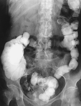
Because the thin-walled alimentary canal does not have sufficient density to be shown through the surrounding structures, demonstration of it on radiograph requires the use of an artificial contrast medium. Barium sulfate, which is a water-insoluble salt of the metallic element barium, is the contrast medium universally used in examinations of the alimentary canal (Fig. 17-11). The barium sulfate used for this purpose is a specially prepared, chemically pure product to which various chemical substances have been added. Barium sulfate is available as either a dry powder or liquid. The powdered barium has different concentrations and is mixed with plain water. The concentration depends on the part to be examined and the preference of the physician.
Many special barium sulfate products are also available. Products with finely divided barium sulfate particles tend to resist precipitation and remain in suspension longer than regular barium preparations. Some barium preparations contain gums or other suspending or dispersing agents and are referred to as suspended or flocculation-resistant preparations. The speed with which the barium mixture passes through the alimentary canal depends on the suspending medium, the temperature of the medium, the consistency of the preparation, and the motile function of the alimentary canal.
In addition to barium sulfate, water-soluble, iodinated contrast media suitable for opacification of the alimentary canal are available (Fig. 17-12). These preparations are modifications of basic IV urographic media, such as diatrizoate sodium and diatrizoate meglumine.
Iodinated solutions move through the gastrointestinal tract quicker than barium sulfate suspensions (Figs. 17-13 and 17-14). An iodinated solution normally clears the stomach in 1 to 2 hours, and the entire iodinated contrast column reaches and outlines the colon in about 4 hours. An orally administered iodinated medium differs from barium sulfate in the following ways:
1. It outlines the esophagus, but it does not adhere to the mucosa as well as a barium sulfate suspension does.
2. It affords an entirely satisfactory examination of the stomach and duodenum including mucosal delineation.
3. It permits a rapid survey of the entire small intestine but fails to provide clear anatomic detail of this portion of the alimentary canal. This failure results from the dilution of the contrast medium and the resultant decrease in opacification.
4. Because of the normal rapid absorption of water through the colonic mucosa, the medium again becomes densely concentrated in the large intestine. Consequently, the entire large intestine is opacified with retrograde filling using a barium sulfate suspension. As a result of its increased concentration and accelerated transit time, a rapid investigation of the large intestine can be performed by the oral route when a patient cannot cooperate for a satisfactory enema study.
A great advantage of water-soluble media is that they are easily removed by aspiration either before or during surgery. If a water-soluble, iodinated medium escapes into the peritoneum through a preexisting perforation of the stomach or intestine, no ill effects result. The medium is readily absorbed from the peritoneal cavity and excreted by the kidneys. This is a definite advantage when perforated ulcers are being investigated.
A disadvantage of iodinated preparations is their strongly bitter taste, which can be masked only to a limited extent. Patients should be forewarned so that they can more easily tolerate ingesting these agents. In addition, these iodinated contrast media are hyperosmolar, encouraging movement of excess fluid into the gastrointestinal tract lumen.
Radiologic apparatus
The fluoroscopic equipment used today contains highly sophisticated image intensification systems (Fig. 17-15). These systems can be connected to accessory units, such as cine film recorders, television systems, spot-film cameras, digital-image cameras, and video recorders. Remote-control fluoroscopic rooms are also available and are used by the fluoroscopist in an adjacent control area (Fig. 17-16). Although conventional IR-loaded spotimage devices are still used with image intensification, digital fluoroscopic units that permit the recording of multiple fluoroscopic images are common.
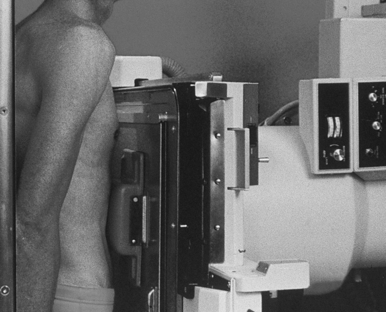
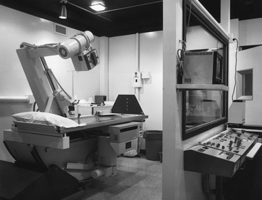
Fig. 17-16 Remote-control fluoroscopic room, showing patient fluoroscopic table (left) and fluoroscopist’s control console (right). The fluoroscopist views the patient through the large window.
Compression and palpation of the abdomen are often performed during an examination of the alimentary canal. Many types of compression devices are available. The fluoroscopic unit shown in Fig. 17-15 shows a compression cone in contact with the patient’s abdomen. This device is often used during general fluoroscopic examinations.
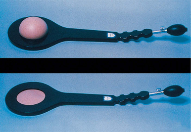
Other types of commercial compression devices include the pneumatic compression paddle shown in Fig. 17-17. This device is often placed under the duodenal bulb and inflated to place pressure on the abdomen. The air is slowly released, and the compression on the body part is eliminated.
Preparation of examining room
The examining room should be completely prepared before the patient enters. In preparing the room, the radiographer should do the following:
• Adjust the equipment controls to the appropriate settings.
• Have the footboard and shoulder support available.
• Check the mechanism of the spot-film device or spot-film camera, or both, and ensure that sufficient films are available.
Before beginning the examination, the radiographer should do the following:
Exposure time
One of the most important considerations in gastrointestinal radiography is the elimination of motion. The highest degree of motor activity is normally found in the stomach and proximal part of the small intestine. The activity gradually decreases along the intestinal tract until it becomes fairly slow in the distal part of the large bowel. Peristaltic speed also depends on the individual patient’s body habitus and is influenced by pathologic changes, use of narcotic pain medication, body position, and respiration. The amount of exposure time for each region must be based on these factors.
In esophageal examinations, the radiographer should observe the following guidelines:
• Use an exposure time of 0.1 second or less for upright radiographs. The time may be slightly longer for recumbent images because the barium descends more slowly when patients are in recumbent positions.
• Barium passes through the esophagus fairly slowly if it is swallowed at the end of full inspiration. The rate of passage is increased if the barium is swallowed at the end of moderate inspiration. The barium is delayed in the lower part for several seconds, however, if it is swallowed at the end of full expiration.
• Respiration is inhibited for several seconds after the beginning of deglutition, which allows sufficient time for the exposure to be made without instructing the patient to hold his or her breath after swallowing.
In examinations of the stomach and small intestine, the radiographer should observe the following guidelines:
• Use an exposure time of no longer than 0.2 second for patients with normal peristaltic activity and never more than 0.5 second; the exposure time should be 0.1 second or less for patients with hypermotility.
• Make exposures of the stomach and intestines at the end of expiration in the routine procedure.
Radiation Protection
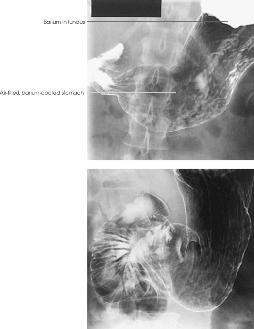
The patient receives radiation during fluoroscopy, spot filming (Fig. 17-18), and radiographic filming for either a partial or a complete gastrointestinal examination. It is taken for granted that properly added filtration is in place at all times in each x-ray tube in the radiology department. It is further assumed that based on the capacity of the machines and the best available accessory equipment, the exposure factors are adjusted to deliver the least possible radiation to the patient.
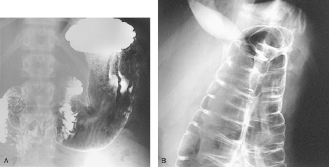
Fig. 17-18 A, AP spot radiograph of barium-filled fundus of stomach. B, Spot radiograph of air-contrast colon, showing left colic flexure.
Protection of the patient from unnecessary radiation is a professional responsibility of the radiographer. (See Chapter 1 in Volume 1 of this atlas for specific guidelines.) In this chapter, the Shield gonads statement at the end of the Position of part section indicates that the patient is to be protected from unnecessary radiation by restricting the radiation beam using proper collimation. Placing lead shielding between the gonads and the radiation source when the clinical objectives of the examination are not compromised is also appropriate.
Esophagus
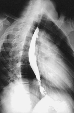
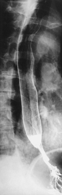
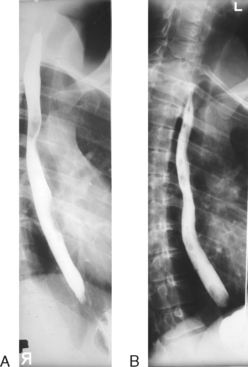
The esophagus may be examined by performing a full-column, single-contrast study in which only barium or watersoluble, iodinated contrast agent is used to fill the esophageal lumen. A doublecontrast procedure also may be used. For this study, high-density barium and carbon dioxide crystals (which liberate carbon dioxide when exposed to water) are the two contrast agents. No preliminary preparation of the patient is necessary. These contrast media procedures show intrinsic lesions and extrinsic pathology impressing on the esophagus. Anatomic structures normally indenting the esophagus must be appreciated to identify pathology. Normally indenting structures include the aortic arch, left main stem bronchus, and left atrium (Fig. 17-19).
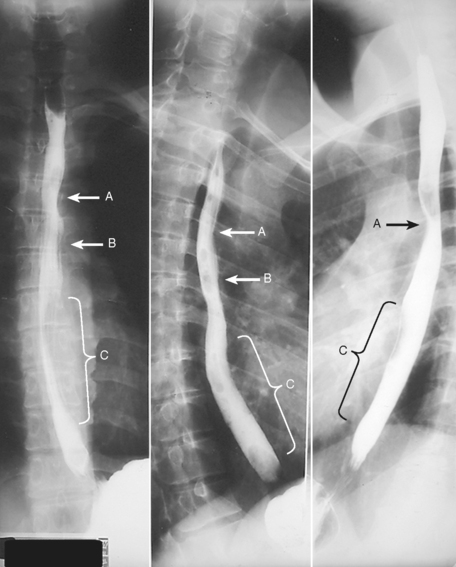
Fig. 17-19 Esophagogram images showing luminal indentations from adjacent anatomy. Normally indented structures include aortic arch (A), left main stem bronchus (B), and left atrium (C).
Barium sulfate mixture
A 30% to 50% weight/volume suspension1 is useful for the full-column, single-contrast technique. A low-viscosity, high-density barium developed for doublecontrast gastric examinations may be used for a double-contrast examination. Whatever the weight/volume concentration of the barium, the most important criterion is that the barium flows sufficiently to coat the walls of the esophagus. The mixing instructions of the barium manufacturer must be followed closely to attain optimal performance of the contrast medium.
Examination procedures
For a single-contrast examination (Figs. 17-20 to 17-22), the following steps are taken:
• Start the fluoroscopic and spot-film examinations with the patient in the upright position whenever possible.
• Use the horizontal and Trendelenburg positions as indicated.
• After the fluoroscopic examination of the heart and lungs and when the patient is upright, instruct the patient to take the cup containing the barium suspension in the left hand and to drink it on request.
The radiologist asks the patient to swallow several mouthfuls of the barium so that the act of deglutition can be observed to determine whether any abnormality is present. The radiologist instructs the patient to perform various breathing maneuvers under fluoroscopic observation so that spot radiographs of areas or lesions not otherwise shown can be obtained.
Performance of a double-contrast esophageal examination (Fig. 17-23) is similar to that of a single-contrast examination. For a double-contrast examination, a free-flowing, high-density barium must be used. A gas-producing substance, usually carbon dioxide crystals, can be added to the barium mixture or given by mouth immediately before the barium suspension is ingested. Spot radiographs are taken during the examination, and delayed images may be obtained on request.
OPAQUE FOREIGN BODIES
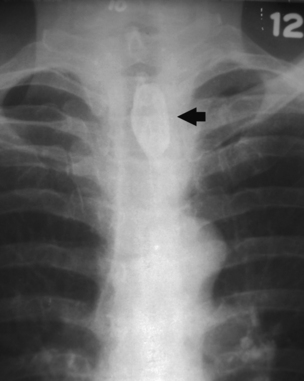
Opaque foreign bodies lodged in the pharynx or in the upper part of the esophagus can usually be shown without the use of a contrast medium. A soft tissue neck or lateral projection of the retrosternal area may be taken for this purpose. A lateral neck radiograph should be obtained at the height of swallowing for the delineation of opaque foreign bodies in the upper end of the intrathoracic esophagus. Swallowing elevates the intrathoracic esophagus a distance of two cervical segments, placing it above the level of the clavicles.
Tufts or pledgets of cotton saturated with a thin barium suspension are sometimes used to show an obstruction or to detect nonopaque foreign bodies in the pharynx and upper esophagus (Fig. 17-24).
Esophagus
 AP, PA, OBLIQUE, AND LATERAL PROJECTIONS
Image receptor: 14 × 17 inch (35 × 43 cm) lengthwise and centered so that the top of the IR is positioned at the level of the mouth for inclusion of the entire esophagus
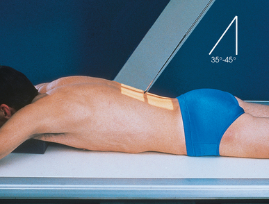
• Position the patient as for chest radiographs (AP, PA, oblique, and lateral; see Chapter 10, Volume 1). Because the RAO position of 35 to 40 degrees (Fig. 17-25) makes it possible to obtain a wider space for an unobstructed image of the esophagus between the vertebrae and the heart, it is usually used in preference to the LAO position. The LPO position has also been recommended.1
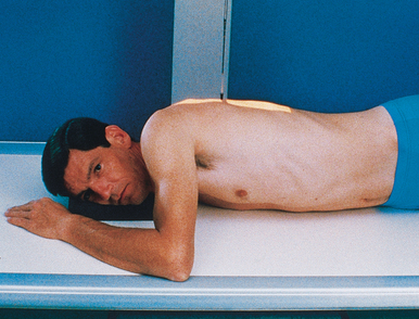
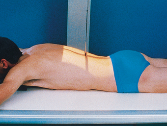
• Unless the upright position is specified, place the patient in the recumbent position for esophageal studies. The recumbent position is used to obtain more complete contrast filling of the esophagus (especially filling of the proximal part) by having the barium column flow against gravity. The recumbent position is routinely used to show variceal distentions of the esophageal veins because varices are best filled by having the blood flow against gravity. Variceal filling is more complete during increased venous pressure, which may be applied by full expiration or by the Valsalva maneuver (see Chapter 15, p. 79).
AP OR PA OBLIQUE PROJECTION
• Position the patient in the RAO or LPO position with the midsagittal plane forming an angle of 35 to 40 degrees from the grid device.
• For the RAO position, adjust the patient’s side-down arm at the side and the side-up arm on the pillow by the head. For the LPO position, do the same, with the side-down arm at the side and the side-up arm on the pillow.
• Center the elevated side to the grid through a plane approximately 2 inches (5 cm) lateral to the midsagittal plane (Fig. 17-26).
LATERAL PROJECTION
• Place the patient’s arms forward, with the forearm on the pillow near the head.
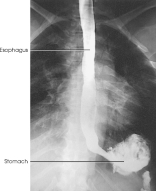
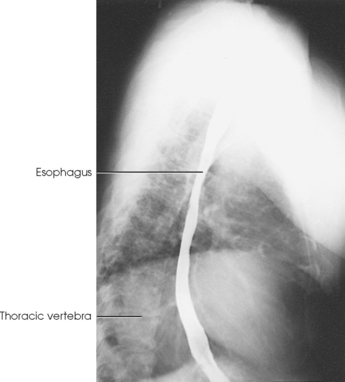
Structures shown: The contrast medium–filled esophagus should be shown from the lower part of the neck to the esophagogastric junction, where the esophagus joins the stomach.
The following should be clearly shown:
AP or PA projection (see Fig. 17-20)
Lateral projection (see Fig. 17-21)
 Patient’s arm not interfering with visualization of the proximal esophagus
Ribs posterior to the vertebrae superimposed to show that the patient was not rotated
NOTE: The general criteria apply to all projections: AP or PA, oblique, and lateral.
Barium administration and respiration:
• Feed the barium sulfate suspension to the patient by spoon, by cup, or through a drinking straw, depending on its consistency.
• Ask the patient to swallow several mouthfuls of barium in rapid succession and then to hold a mouthful until immediately before the exposure.
• To show esophageal varices, instruct the patient (1) to expirate fully and then swallow the barium bolus and avoid inspiration until the exposure has been made or (2) to take a deep breath and, while holding the breath, swallow the bolus and then perform the Valsalva maneuver (Fig. 17-27, A).
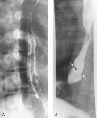
Fig. 17-27 A, Spot-film studies showing esophageal varices. B, Barium bolus clearly shows Schatzki ring (arrows). (Courtesy Michael J. Kudlas, MEd, RT(R)(QM).)
• For other conditions, instruct the patient simply to swallow the barium bolus, which is normally done during moderate inspiration (Fig. 17-27, B). Because respiration is inhibited for about 2 seconds after swallowing, the patient does not have to hold his or her breath for the exposure. If the contrast medium is swallowed at the end of full inspiration, make two or three exposures in rapid succession before the contrast medium passes into the stomach. To show the entire esophagus, it is sometimes necessary to make the exposure while the patient is drinking the barium suspension through a straw in rapid and continuous swallows.
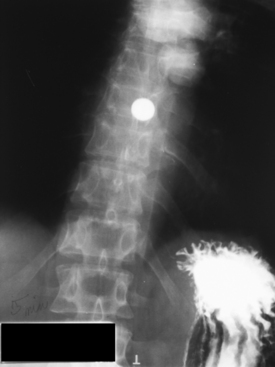
• Ask the patient to swallow a barium tablet to evaluate the degree of lumen narrowing with esophageal structure (Fig. 17-28).
Stomach: Gastrointestinal Series
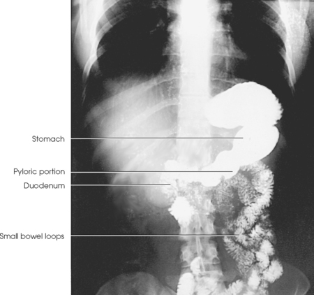
Upper gastrointestinal (UGI) tract radiographs are used to evaluate the distal esophagus, stomach, and some or all of the small intestine. A UGI examination (Fig. 17-29), usually called a gastrointestinal or UGI series, may include the following:
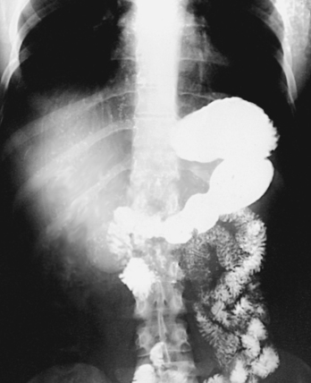
1. A preliminary radiograph of the abdomen to delineate the liver, spleen, kidneys, psoas muscles, and bony structures and to detect any abdominal or pelvic calcifications or tumor masses. The detection of calcifications and tumor masses requires that the survey radiograph of the abdomen be taken after preliminary cleansing of the intestinal tract but before administration of the contrast medium.
2. An examination consisting of fluoroscopic and serial radiographic studies of the esophagus, stomach, and duodenum using an ingested opaque mixture, usually barium sulfate.
3. When requested, a small intestine study consisting of radiographs obtained at frequent intervals during passage of the contrast column through the small intestine, at which time the vermiform appendix and the ileocecal region may be examined.
Ambulatory outpatients or acutely ill patients, such as patients with a bleeding ulcer, are usually examined in the supine position using a fluoroscopic and spot-film procedure. Everything possible should be done to expedite the procedure. Any contrast preparation must be ready, and the examination room must be fully prepared before the patient is brought into the radiology department.
PRELIMINARY PREPARATION
Because a gastrointestinal series is time-consuming, the patient should be told the approximate time required for the procedure before being assigned an appointment for an examination. The patient also needs to understand the reason for preliminary preparation so that full cooperation can be given.
The stomach must be empty for an examination of the UGI tract (the stomach and small intestine). It is also desirable to have the colon free of gas and fecal material. When the patient is constipated, a non–gas-forming laxative may be administered 1 day before the examination.
An empty stomach is ensured by withholding food and water after midnight for 8 to 9 hours before the examination. When a small intestine study is to be made, food and fluid are withheld after the evening meal.
Because it is believed that nicotine and chewing gum stimulate gastric secretion and salivation, some physicians tell patients not to smoke or chew gum after midnight on the night before the examination. This restriction is intended to prevent excessive fluid from accumulating in the stomach and diluting the barium suspension enough to interfere with its coating property.
Barium sulfate suspension
The contrast medium generally used in routine gastrointestinal examinations is barium sulfate mixed with water. The preparation must be thoroughly mixed according to the manufacturer’s instructions. Specially formulated, high-density barium is also available. Advances in the production of barium have all but eliminated the use of a single barium formula for most gastrointestinal examinations performed in the radiology department.
Most physicians use one of the many commercially prepared barium suspensions. These products are available in several flavors, and some are conveniently packaged in individual cups containing the dry ingredients. To these products, the radiographer merely has to add water, recap the cup, and shake it to obtain a smooth suspension. Other barium suspensions are completely mixed and ready to use.
Contrast Studies
Two general procedures are routinely used to examine the stomach: the singlecontrast method and the double-contrast method. A biphasic examination is a combination of the single-contrast and double-contrast methods during the same procedure. Hypotonic duodenography is another, less commonly used examination.
SINGLE-CONTRAST EXAMINATION
In the single-contrast method (Fig. 17-30), a barium sulfate suspension is administered during the initial fluoroscopic examination. The barium suspension used for this study is usually in the 30% to 50% weight/volume range.1 The procedure is as follows:
• Whenever possible, begin the examination with the patient in the upright position.
• The radiologist may first examine the heart and lungs fluoroscopically and observe the abdomen to determine whether food or fluid is in the stomach.
• Give the patient a glass of barium and instruct the patient to drink it as requested by the radiologist. If the patient is in the recumbent position, administer the suspension through a drinking straw.
• The radiologist asks the patient to swallow two or three mouthfuls of the barium. During this time, examine and expose any indicated spot films of the esophagus. By manual manipulation of the stomach through the abdominal wall, the radiologist then coats the gastric mucosa.
• Obtain images with the spot-film device or another compression device to show a mucosal lesion of the stomach or duodenum.
• After studying the rugae and as the patient drinks the remainder of the barium suspension, observe the filling of the stomach and examine the duodenum further. Based on this examination, the following can be accomplished:
The contrast medium normally begins to pass into the duodenum almost immediately. Nervous tension of the patient may delay transit of the contrast material, however.
Fluoroscopy is performed with the patient in the upright and recumbent positions while the body is rotated and the table is angled so that all aspects of the esophagus, stomach, and duodenum are shown. Spot films are exposed as indicated. If esophageal involvement is suspected, a study is usually made with a thick barium suspension. Subsequent radiographs of the stomach and duodenum should be obtained immediately after fluoroscopy before any considerable amount of the barium suspension passes into the jejunum.
Position of patient
The stomach and duodenum may be examined using PA, AP, oblique, and lateral projections with the patient in the upright and recumbent positions, as indicated by the fluoroscopic findings.
One variation of the supine positions is the LPO position. In another variation, the head end of the table is lowered 25 to 30 degrees to show a hiatal hernia. Finally, to show esophageal regurgitation and hiatal hernias, the head end of the table is lowered 10 to 15 degrees and the patient is rotated slightly toward the right side to place the esophagogastric (gastroesophageal) junction in profile to the right of the spine. The medical significance of diagnosing hiatal hernias is a topic that has received much attention in recent years. Some authors report little correlation between the presence of a hiatal hernia and gastrointestinal symptoms. If little correlation exists, radiographic evaluation is of little value in most hiatal hernias.
DOUBLE-CONTRAST EXAMINATION
A second approach to the examination of the gastrointestinal tract is the double-contrast technique (Fig. 17-31). The principal advantages of this method over the single-contrast method are that small lesions are less easily obscured and the mucosal lining of the stomach can be more clearly visualized. For successful results, the patient must be able to move with relative ease throughout the examination.
For double-contrast studies, the procedure is as follows:
• To begin the examination, place the patient on the fluoroscopic table in the upright position.
• Give the patient a gas-producing substance in the form of a powder, crystals, pills, or a carbonated beverage. (An older technique involved placing pinholes in the sides of a drinking straw so that the patient ingested air while drinking the barium suspension during the examination.)
• Give the patient a small amount of commercially available, high-density barium suspension. For even coating of the stomach walls, the barium must flow freely and have a low viscosity. Many high-density barium products are available; these suspensions have weight/volume ratios of up to 250%.
• Place the patient in the recumbent position, and instruct him or her to turn from side to side or to roll over a few times. This movement serves to coat the mucosal lining of the stomach as the carbon dioxide continues to expand. The patient may feel the need to belch but should refrain from doing so until the examination is finished to ensure that an optimal amount of contrast material (gas) remains for the duration of the examination.
• Just before the examination, the patient may be given glucagon or other anticholinergic medications intravenously or intramuscularly to relax the gastrointestinal tract. These medications improve visualization by inducing greater distention of the stomach and intestines. Before administering these agents, the radiologist must consider numerous factors, including side effects, contraindications, availability, and cost.
Radiographic imaging procedure
The conventional images obtained after the fluoroscopic examination may be the same as the images obtained for the single-contrast examination. Often the radiographs with the greatest amount of diagnostic information are the spot images taken during fluoroscopy. In most cases, the radiologist will have already obtained most of the necessary diagnostic radiographs. Nonfluoroscopic images may be unnecessary.
BIPHASIC EXAMINATION
The biphasic gastrointestinal examination incorporates the advantages of the single-contrast and double-contrast UGI examinations, with both examinations performed during the same procedure. The patient first undergoes a double-contrast examination of the UGI tract. When this study is completed, the patient is given an approximately 15% weight/volume barium suspension, and a single-contrast examination is performed. This biphasic approach increases the accuracy of diagnosis without significantly increasing the cost of the examination.
HYPOTONIC DUODENOGRAPHY
The use of hypotonic duodenography as a primary diagnostic tool has decreased in recent years. When lesions beyond the duodenum are suspected, the doublecontrast gastrointestinal examination described can aid in the diagnosis. When pancreatic disease is suspected, computed tomography (CT) or needle biopsy can also be used. Hypotonic duodenography is less frequently necessary.
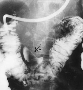
First described by Liotta,1 hypotonic duodenography requires intubation (Figs. 17-32 and 17-33) and is used to evaluate postbulbar duodenal lesions and detect pancreatic disease. A newer tubeless technique requires temporary drug-induced duodenal paralysis so that a doublecontrast examination can be performed without interference from peristaltic activity. During the atonic state when the duodenum is distended with the contrast medium to two or three times its normal size, it presses against and outlines any abnormality in the contour of the head of the pancreas.
Stomach and Duodenum
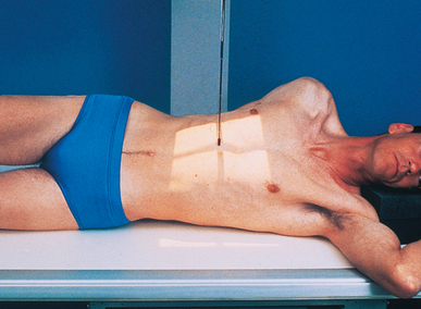
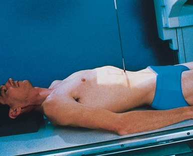
• For radiographic studies of the stomach and duodenum, place the patient in the recumbent position. The upright position is sometimes used to show the relative position of the stomach.
• When adjusting thin patients in the prone position, support the weight of the body on pillows or other suitable pads positioned under the thorax and pelvis. This adjustment keeps the stomach or duodenum from pressing against the vertebrae, with resultant pressure-filling defects.
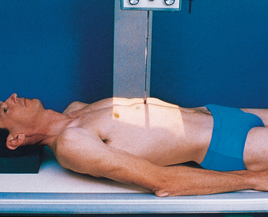
• Adjust the patient’s position either recumbent or upright so that the midline of the grid coincides with a sagittal plane passing halfway between the vertebral column and the left lateral border of the abdomen (Fig. 17-34).
• Center the IR about 1 to 2 inches (2.5 to 5 cm) above the lower rib margin at the level of L1-2 when the patient is prone (Figs. 17-35 and 17-36).
• For upright images, center the IR 3 to 6 inches (7.6 to 15 cm) lower than L1-2. The greatest visceral movement between the prone and upright positions occurs in asthenic patients.
• Do not apply an immobilization band for standard radiographic projections of the stomach and intestines because the pressure is likely to cause filling defects and because it interferes with emptying and filling of the duodenal bulb, factors that are important in serial studies.
• Respiration: Suspend at the end of expiration unless otherwise requested.
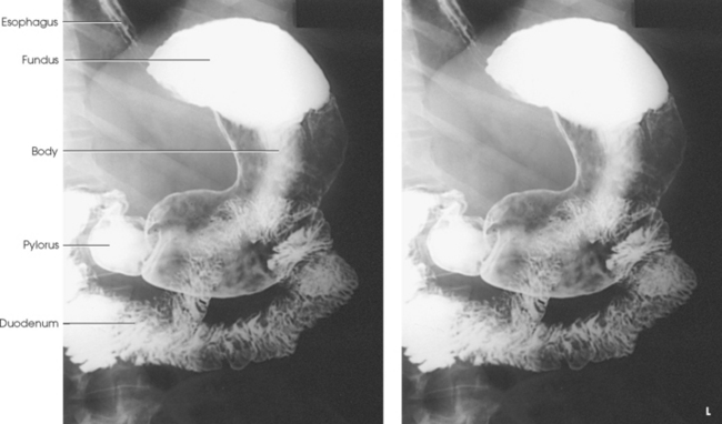
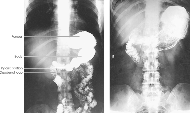
Structures shown: A PA projection of the contour of the barium-filled stomach and duodenal bulb is shown. The upright projection shows the size, shape, and relative position of the filled stomach, but it does not adequately show the unfilled fundic portion of the organ. In the prone position, the stomach moves superiorly 1½ to 4 inches (3.8 to 10 cm) according to the patient’s body habitus (Figs. 17-37 to 17-40). At the same time, the stomach spreads horizontally, with a comparable decrease in its length. (Note that the fundus usually fills in asthenic patients.)
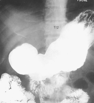
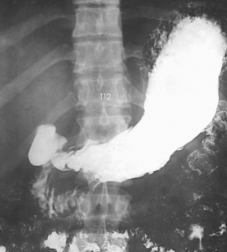
The pyloric canal and duodenal bulb are well shown in patients with an asthenic or a hyposthenic habitus. These structures are often partially obscured in patients with a sthenic habitus and, except in the PA axial projection, are completely obscured by the prepyloric portion of the stomach in patients with a hypersthenic habitus.
PA AXIAL PROJECTION
• Adjust the patient’s body so that the midsagittal plane is centered to the grid.
• For a sthenic patient, center the IR at the level of L2 (Fig. 17-41); center it higher for a hypersthenic patient and lower for an asthenic patient. L2 lies about 1 to 2 inches (2.5 to 5 cm) above the lower rib margin.
• Respiration: Suspend respiration at the end of expiration unless otherwise requested.
• Directed to the midpoint of the IR at an angle of 35 to 45 degrees cephalad. Gugliantini1 recommended a cephalic angulation of 20 to 25 degrees to show the stomach in infants.
Structures shown: Gordon1 developed the PA axial projection to “open up” the high, horizontal (hypersthenic-type) stomach to show the greater and lesser curvatures, the antral portion of the stomach, the pyloric canal, and the duodenal bulb. The resultant image gives a hypersthenic stomach much the same configuration as the average sthenic type of stomach (Fig. 17-42).
PA OBLIQUE PROJECTION
• After the PA projection, instruct the patient to rest the head on the right cheek and to place the right arm along the side of the body.
• Have the patient raise his or her left side and support the body on the left forearm and flexed left knee.
• Adjust the patient’s position so that a sagittal plane passing midway between the vertebrae and the lateral border of the elevated side coincides with the midline of the grid (Fig. 17-43).
• Center the IR about 1 to 2 inches (2.5 to 5 cm) above the lower rib margin, at the level of L1-2, when the patient is prone.
• Make the final adjustment in body rotation. The approximately 40 to 70 degrees of rotation required to give the best image of the pyloric canal and duodenum depend on the size, shape, and position of the stomach. Generally, hypersthenic patients require a greater degree of rotation than sthenic and asthenic patients.
• The RAO position is used for serial studies of the pyloric canal and the duodenal bulb because gastric peristalsis is usually more active when the patient is in this position.
• Respiration: Suspend at the end of expiration unless otherwise requested.
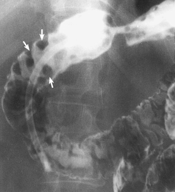
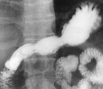
Structures shown: A PA oblique projection of the stomach and entire duodenal loop is presented. This projection gives the best image of the pyloric canal and the duodenal bulb in patients whose habitus approximates the sthenic type (Figs. 17-44 and 17-45).
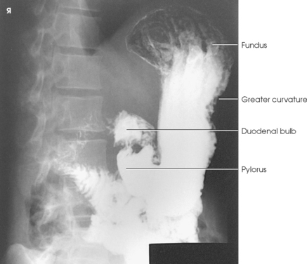
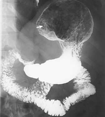
Fig. 17-45 Double-contrast PA oblique stomach and duodenum. Note esophagus entering stomach (arrow).
Because gastric peristalsis is generally more active with the patient in the RAO position, a serial study of several exposures is sometimes obtained at intervals of 30 to 40 seconds to delineate the pyloric canal and duodenal bulb.
AP OBLIQUE PROJECTION
• Have the patient abduct the left arm and place the hand near the head, or place the extended arm alongside the body.
• Place the right arm alongside the body or across the upper chest, as preferred.
• Have the patient turn toward the left, resting on the left posterior body surface.
• Flex the patient’s right knee, and rotate the knee toward the left for support.
• Place a positioning sponge against the patient’s elevated back for immobilization.
• Adjust the patient’s position so that a sagittal plane passing approximately midway between the vertebrae and the left lateral margin of the abdomen is centered to the IR.
• Adjust the center of the IR at the level of the body of the stomach. The centering would be at a point midway between the xiphoid process and the lower margin of the ribs (Fig. 17-46).
• The degree of rotation required to show the stomach best depends on the patient’s body habitus. An average angle of 45 degrees should be sufficient for a sthenic patient, but the degree of angulation can vary from 30 to 60 degrees.
• Respiration: Suspend at the end of expiration unless otherwise instructed.
Structures shown: The AP oblique projection shows the fundic portion of the stomach (Fig. 17-47). Because of the effect of gravity, the pyloric canal and duodenal bulb are not as filled with barium as they are in the opposite and complementary position (the RAO position; see Figs. 17-43 to 17-45).
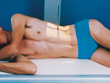
LATERAL PROJECTION
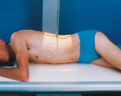
• With the patient in either the upright or recumbent position, adjust the body so that a plane passing midway between the midcoronal plane and the anterior surface of the abdomen coincides with the midline of the grid.
• Center the IR at the level of L1-2 for the recumbent position (about 1 to 2 inches [2.5 to 5 cm] above the lower rib margin) and at L3 for the upright position.
• Adjust the body in a true lateral position (Fig. 17-48).
• Respiration: Suspend at the end of expiration unless otherwise requested.
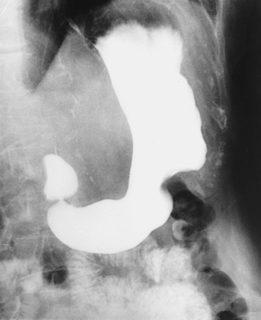
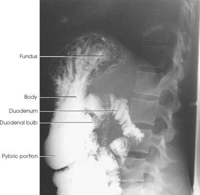
Structures shown: A lateral projection shows the anterior and posterior aspects of the stomach, the pyloric canal, and the duodenal bulb (Figs. 17-49 and 17-50). The right lateral projection commonly affords the best image of the pyloric canal and the duodenal bulb in patients with a hypersthenic habitus.
AP PROJECTION
Image receptor: 10 × 12 inch (24 × 30 cm) lengthwise for small hiatal hernias; 14 × 17 inch (35 × 43 cm) lengthwise for large diaphragmatic herniations or for the stomach and small bowel
• Place the patient in the supine position. The stomach moves superiorly and to the left in this position, and, except in thin patients, its pyloric end is elevated so that the barium flows into and fills its cardiac or fundic portions or both. The filling of the fundus displaces the gas bubble into the pyloric end of the stomach, where it allows double-contrast delineation of posterior wall lesions when a single-contrast examination is performed. If the patient is thin, the intestinal loops do not move superior enough to tilt the stomach for fundic filling. Rotating the patient’s body toward the left or angling the head end of the table downward is necessary.
• Tilt the table to full or partial Trendelenburg angulation to show diaphragmatic herniations (Fig. 17-51). In the Trendelenburg position, the involved organ or organs, which may appear to be normally located in all other body positions, shift upward and protrude through the hernial orifice (most commonly through the esophageal hiatus).
NOTE: Valsalva maneuver may be used in conjunction with or as an alternative to the Trendelenburg position.
• Adjust the position of the patient so that the midline of the grid coincides (1) with the midline of the body when a 14- × 17-inch (35- × 43-cm) IR is used (see Fig. 17-51) or (2) with a sagittal plane passing midway between the midline and the left lateral margin of the abdomen when a 10- × 12-inch (24- × 30-cm) IR is used (Fig. 17-52). Longitudinal centering of the large IR depends on the extent of hernial protrusion into the thorax and is determined during fluoroscopy.
• For the stomach and duodenum, center the 10- × 12-inch (24- × 30-cm) IR at a level midway between the xiphoid process and the lower rib margin (approximately L1-2). For the 14- × 17-inch (35- × 43-cm) IR, center it at the same level and adjust up or down slightly, depending on whether the diaphragm or small bowel needs to be seen.
• Respiration: Suspend at the end of expiration unless otherwise requested.
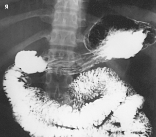
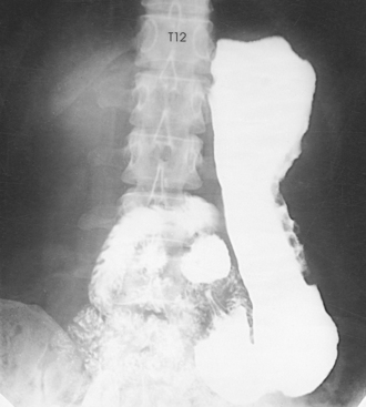
Stomach: An AP projection of the stomach shows a well-filled fundic portion and usually a double-contrast delineation of the body, pyloric portion, and duodenum (Fig. 17-53). Because of the elevation and superior displacement of the stomach, this projection affords the best AP projection of the retrogastric portion of the duodenum and jejunum.
Diaphragm: An AP projection of the abdominothoracic region shows the organ or organs involved in, and the location and extent of, any gross hernial protrusion through the diaphragm (Figs. 17-54 and 17-55).
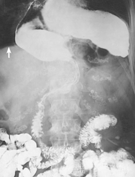
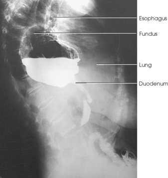
Fig. 17-55 Upright left lateral stomach showing hiatal hernia. (Comparison lateral radiographs are shown in Figs. 17-49 and 17-50.)
The following should be clearly shown:
Evidence of proper collimation
Entire stomach and duodenal loop
Double-contrast visualization of the gastric body, pylorus, and duodenal bulb
Retrogastric portion of the duodenum and jejunum
Lower lung fields on 14- × 17-inch (35- × 43-cm) radiographs to show diaphragmatic hernias
Stomach centered at the level of the pylorus on 10- × 12-inch (24- × 30-cm) radiographs
Superior Stomach and Distal Esophagus
WOLF METHOD (FOR HIATAL HERNIA)
RAO position
The Wolf method1 is a modification of the Trendelenburg position. The technique was developed for the purpose of applying greater intra-abdominal pressure than is provided by body angulation alone and ensuring more consistent results in the radiographic demonstration of small, sliding gastroesophageal herniations through the esophageal hiatus.
The Wolf method requires the use of a semicylindric radiolucent compression device measuring 22 inches (55 cm) in length, 10 inches (24 cm) in width, and 8 inches (20 cm) in height. (The compression sponge depicted in Fig. 17-56 is slightly smaller than the one described by Wolf.)
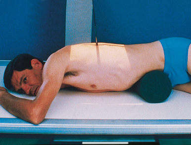
Wolf and Guglielmo1 stated that this compression device not only provides Trendelenburg angulation of the patient’s trunk, but also increases intra-abdominal pressure enough to permit adequate contrast filling and maximal distention of the entire esophagus. A further advantage of the device is that it does not require angulation of the table; the patient can hold the barium container and ingest the barium suspension through a straw with comparative ease.
NOTE: Valsalva maneuver also increases intraabdominal pressure and may be used instead of the Wolf method.
• Instruct the patient to assume a modified knee-chest position during placement of the compression device.
• Place the compression device horizontally under the abdomen and just below the costal margin.
• Adjust the patient in a 40- to 45-degree RAO position, with the thorax centered to the midline of the grid.
• Instruct the patient to ingest the barium suspension in rapid, continuous swallows.
• To allow for complete filling of the esophagus, make the exposure during the third or fourth swallow (see Fig. 17-56).
Structures shown: The Wolf method shows the relationship of the stomach to the diaphragm and is useful in diagnosing a hiatal hernia (Fig. 17-57).
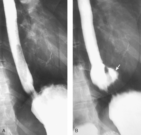
Fig. 17-57 Comparison PA axial oblique images in one patient. A, Without abdominal compression: no evidence of hernia. B, With abdominal compression: obvious large sliding hernia (arrow).
Small Intestine
Radiologic examinations of the small intestine are performed by administering a barium sulfate preparation (1) by mouth; (2) by complete reflux filling with a large-volume barium enema (BE); or (3) by direct injection into the bowel through an intestinal tube, a technique that is called enteroclysis, or small intestine enema. The latter two methods are used when the oral method fails to provide conclusive information.1 Enteroclysis is technically difficult, so its use is usually limited to larger medical facilities.
PREPARATION FOR EXAMINATION
Preferably, the patient has a soft or low-residue diet for 2 days before the small intestine study. Because of economics, however, it often is impossible to delay the examination for 2 days. Food and fluid are usually withheld after the evening meal of the day before the examination, and breakfast is withheld on the day of the study. A cleansing enema may be administered to clear the colon; however, an enema is not always recommended for enteroclysis because enema fluid may be retained in the small intestine. The barium formula varies depending on the method of examination. The patient’s bladder should be empty before and during the procedure to avoid displacing or compressing the ileum.
ORAL METHOD OF EXAMINATION
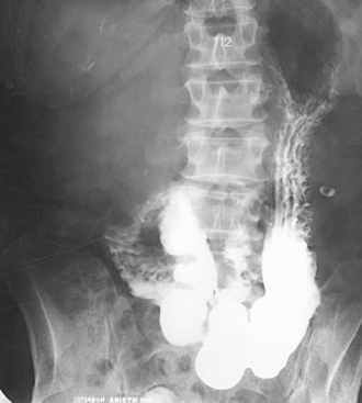
The radiographic examination of the small intestine is usually termed a small bowel series because several identical radiographs are done at timed intervals. The oral examination, or ingestion of barium through the mouth, is usually preceded by a preliminary radiograph of the abdomen. Each radiograph of the small intestine is identified with a time marker indicating the interval between its exposure and the ingestion of barium. The studies are made with the patient in either the supine or the prone position. The supine position is used (1) to take advantage of the superior and lateral shift of the barium-filled stomach for visualization of the retrogastric portions of the duodenum and jejunum and (2) to prevent possible compression overlapping of loops of the intestine. The prone position is used to compress the abdominal contents, which increases radiographic quality. For the final radiographs in thin patients, it may be necessary to angle the table into the Trendelenburg position to “unfold” low-lying and superimposed loops of the ileum.
The first small intestine radiograph is usually taken 15 minutes after the patient drinks the barium. The interval to the next exposure varies from 15 to 30 minutes depending on the average transit time of the barium sulfate preparation used. Regardless of the barium preparation used, the radiologist inspects the radiographs as they are processed and varies the procedure according to the requirements for the individual patient. Fluoroscopic and radiographic studies (spot or conventional) may be made of any segment of the bowel as the loops become opacified.
Some radiologists request that a glass of ice water (or another routinely used food stimulant) be given to a patient with hypomotility after 3 or 4 hours of administrating barium sulfate to accelerate peristalsis. Others give patients a watersoluble gastrointestinal contrast medium, tea, or coffee to stimulate peristalsis. Other radiologists administer peristaltic stimulants every 15 minutes through the transit time. With these methods, the transit of the medium is shown fluoroscopically, spot and conventional radiographs are exposed as indicated, and the examination is usually completed in 30 to 60 minutes.