GENERAL ANATOMY AND RADIOGRAPHIC POSITIONING TERMINOLOGY
General Anatomy
Radiographers must possess a thorough knowledge of anatomy, physiology, and osteology to obtain radiographs that show the desired body part. Anatomy is the term applied to the science of the structure of the body. Physiology is the study of the function of the body organs. Osteology is the detailed study of the body of knowledge relating to the bones of the body.
Radiographers also must have a general understanding of all body systems and their functions. Particular attention must be given to gaining a thorough understanding of the skeletal system and the surface landmarks used to locate different body parts. The radiographer must be able to visualize mentally the internal structures that are to be radiographed. By using external landmarks, the radiographer should properly position body parts to obtain the best diagnostic radiographs possible.
BODY PLANES
The full dimension of the human body as viewed in the anatomic position (see Chapter 1) can be effectively subdivided through the use of imaginary body planes. These planes slice through the body at designated levels from all directions. The following four fundamental body planes referred to regularly in radiography are illustrated in Fig. 3-1, A:
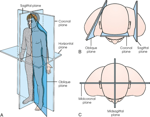
Fig. 3-1 Planes of the body. A, A patient in anatomic position with four planes identified. B, Top-down perspective of patient’s body showing sagittal plane through left shoulder, coronal plane through anterior head, and oblique plane through right shoulder. C, Midsagittal plane dividing body equally into right and left halves and midcoronal plane dividing body equally into anterior and posterior halves. Sagittal, coronal, and horizontal planes are always at right angles to one another.
Sagittal plane
A sagittal plane divides the entire body or a body part into right and left segments. The plane passes vertically through the body from front to back (see Fig. 3-1, A and B). The midsagittal plane is a specific sagittal plane that passes through the midline of the body and divides it into equal right and left halves (Fig. 3-1, C).
Coronal plane
A coronal plane divides the entire body or a body part into anterior and posterior segments. The plane passes through the body vertically from one side to the other (see Fig. 3-1, A and B). The midcoronal plane is a specific coronal plane that passes through the midline of the body, dividing it into equal anterior and posterior halves (see Fig. 3-1, C). This plane is sometimes referred to as the midaxillary plane.
Horizontal plane
A horizontal plane passes crosswise through the body or a body part at right angles to the longitudinal axis. It is positioned at a right angle to the sagittal and coronal planes. This plane divides the body into superior and inferior portions. Often it is referred to as a transverse, axial, or cross-sectional plane (see Fig. 3-1, A).
Oblique plane
An oblique plane can pass through a body part at any angle among the three previously described planes (see Fig. 3-1, A and B). Planes are used in radiographic positioning to center a body part to the image receptor (IR) or central ray and to ensure that the body part is properly oriented and aligned with the IR. The midsagittal plane may be centered and perpendicular to the IR with the long axis of the IR parallel to the same plane. Planes can also be used to guide projections of the central ray. The central ray for an anteroposterior (AP) projection passes through the body part parallel to the sagittal plane and perpendicular to the coronal plane. Quality imaging requires attention to all relationships among body planes, the IR, and the central ray.
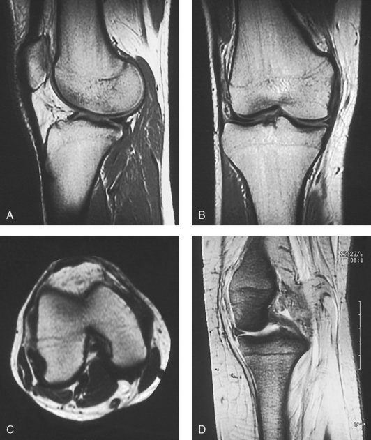
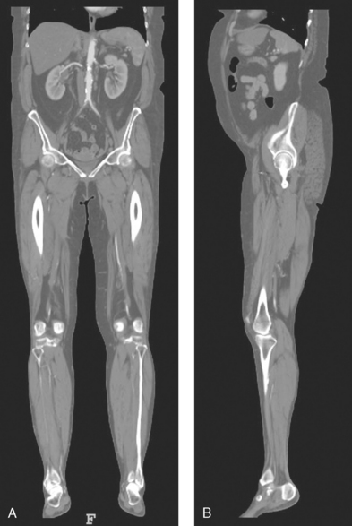
Body planes are used in computed tomography (CT), magnetic resonance imaging (MRI), and ultrasound (US) to identify the orientation of anatomic cuts or slices shown in the procedure (Fig. 3-2). Imaging in several planes is often used to show large sections of anatomy (Fig. 3-3).
SPECIAL PLANES
Two special planes are used in radiographic positioning. These planes are localized to a specific area of the body only.
Interiliac plane
The interiliac plane transects the pelvis at the top of the iliac crests at the level of the fourth lumbar spinous process (Fig. 3-4, A). It is used in positioning the lumbar spine, sacrum, and coccyx.
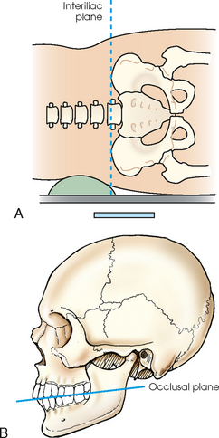
Occlusal plane
The occlusal plane is formed by the biting surfaces of the upper and lower teeth with the jaws closed (Fig. 3-4, B). It is used in positioning of the odontoid process and some head projections.
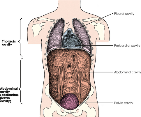
BODY CAVITIES
The two great cavities of the torso are the thoracic and abdominal cavities (Fig. 3-5). The thoracic cavity is subdivided into a pericardial segment and two pleural portions. Although the abdominal cavity has no intervening partition, the lower portion is called the pelvic cavity. Some anatomists combine the abdominal and pelvic cavities and refer to them as the abdominopelvic cavity. The principal structures located in the cavities are listed on the following page.
DIVISIONS OF THE ABDOMEN
The abdomen is the portion of the trunk that is bordered superiorly by the diaphragm and inferiorly by the superior pelvic aperture (pelvic inlet). The location of organs or an anatomic area can be described by dividing the abdomen according to one of two methods: four quadrants or nine regions.
Quadrants
The abdomen is often divided into four clinical divisions called quadrants (Fig. 3-6). The midsagittal plane and a horizontal plane intersect at the umbilicus and create the boundaries. The quadrants are named as follows:
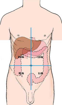
Dividing the abdomen into four quadrants is useful for describing the location of the various abdominal organs. For example, the spleen can be described as being located in the left upper quadrant.
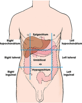
Regions
Some anatomists divide the abdomen into nine regions by using four planes (Fig. 3-7). These anatomic divisions are not used as often as quadrants in clinical practice. The nine regions of the body, divided into three groups, are named as follows:
SURFACE LANDMARKS
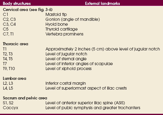
Most anatomic structures cannot be visualized directly; the radiographer must use various protuberances, tuberosities, and other external indicators to position the patient accurately. These surface landmarks enable the radiographer to obtain radiographs of optimal quality consistently for a wide variety of body types. If surface landmarks are not used for radiographic positioning or if they are used incorrectly, the chance of having to repeat the radiograph greatly increases.
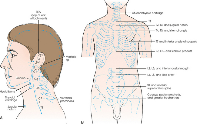
Many commonly used landmarks are listed in Table 3-1 and diagrammed in Fig. 3-8. These landmarks are accepted averages for most patients and should be used only as guidelines. Variations in anatomic build or pathologic conditions may warrant positioning compensation on an individual basis. The ability to compensate is gained through experience.
BODY HABITUS
Common variations in the shape of the human body are termed the body habitus. 1 determined the primary classifications of body habitus based on his study of 1000 patients. The specific type of body habitus is important in radiography because it determines the size, shape, and position of the organs of the thoracic and abdominal cavities.
Body habitus directly affects the location of the following:
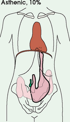
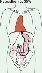
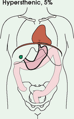
An organ such as the gallbladder may vary in position by 8 inches, depending on the body habitus. The stomach may be positioned horizontally, high, and in the center of the abdomen for one type of habitus and positioned vertically, low, and to the side of the midline in another type. Fig. 3-9 shows an example of the placement, shape, and size of the lungs, heart, and diaphragm in patients with four different body habitus types.
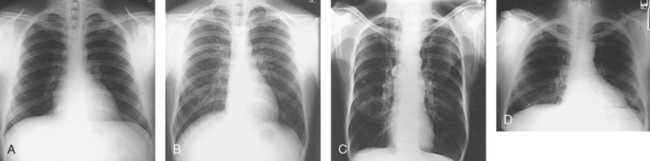
Fig. 3-9 Placement, shape, and size of lungs, heart, and diaphragm in patients with four different body habitus types. A, Sthenic. B, Hyposthenic. C, Asthenic. D, Hypersthenic.
Body habitus and the placement of the thoracic and abdominal organs are also important in the determination of technical and exposure factors for the appropriate radiographic density and contrast and the radiation doses. Contrast medium in the gallbladder may affect the automatic exposure control detector. For one type of habitus, the gallbladder may lie directly over the detector (which is undesirable); for another, it may not even be near the detector. The standard placement and size of the IR may have to be changed because of body habitus. The selection of kilovolt (peak) and milliampere-second exposure factors may also be affected by the type of habitus because of wide variations in physical tissue density. These technical considerations are described in greater detail in radiography physics and imaging texts.
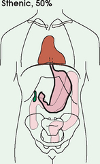
Box 3-1 describes specific characteristics of the four types of body habitus and outlines their general shapes and variations. The four major types of body habitus and their approximate frequency in the population are identified as follows:
BOX 3-1 Four types of body habitus: prevalence, organ placement, and characteristics
Heart: Nearly vertical and at midline
Lungs: Long, apices above clavicles, may be broader above base
Build: Frail
Organs and characteristics for this habitus are intermediate between sthenic and asthenic body habitus types; this habitus is the most difficult to classify
More than 85% of the population has either a sthenic or hyposthenic body habitus. The sthenic type is considered the dominant type of habitus. The relative shape of patients with a sthenic or hyposthenic body habitus and the position of their organs are referred to in clinical practice as ordinary or average. All standard radiographic positioning and exposure techniques are based on these two groups. Radiographers must become thoroughly familiar with the characteristics and organ placements of these two body types.
Radiographers must also become familiar with the two extreme habitus types: asthenic and hypersthenic. In these two small groups (15% of the population), the placement and size of the organs significantly affect positioning and the selection of exposure factors. Consequently, radiography of these patients can be challenging. Experience and professional judgment enable the radiographer to determine the correct body habitus and to judge the specific location of the organs.
Body habitus is not an indication of disease or other abnormality, and it is not determined by the body fat or physical condition of the patient. Habitus is simply a classification of the four general shapes of the trunk of the human body. When positioning patients, the radiographer should be conscious that habitus is not associated with height or weight. Four patients of equal height could have four different trunk shapes (Fig. 3-10).
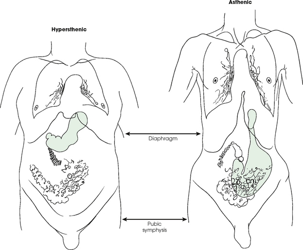
Fig. 3-10 Different trunks are shown for asthenic and hypersthenic habitus, the two extremes. The abdomen is the same length in both patients (diaphragm to pubic symphysis). The abdominal organs are in completely different positions. Note high stomach in hypersthenic habitus (green color) and low stomach in asthenic habitus. (Art is based on actual autopsy findings by R. Walter Mills, MD.)
Osteology
The adult human skeleton is composed of 206 primary bones. Ligaments unite the bones of the skeleton. Bones provide the following:
• Mechanical basis for movement
• Protection of internal organs
The 206 bones of the body are divided into two main groups:
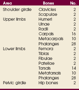
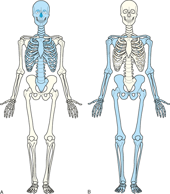
The axial skeleton supports and protects the head and trunk with 80 bones (Table 3-2). The appendicular skeleton allows the body to move in various positions and from place to place with its 126 bones (Table 3-3). Fig. 3-11 identifies these two skeletal areas.
TABLE 3-2
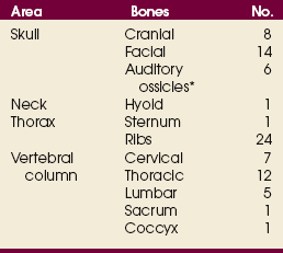
*Auditory ossicles are small bones in the ears. They are not considered ofofficial bones of the axial skeleton but are placed here for convenience.
GENERAL BONE FEATURES
The general features of most bones are shown in Fig. 3-12. All bones are composed of a strong, dense outer layer called the compact bone and an inner portion of less dense spongy bone. The hard outer compact bone protects the bone and gives it strength for supporting the body. The softer spongy bone contains a spiculated network of interconnecting spaces called the trabeculae (Fig. 3-13). The trabeculae are filled with red and yellow marrow. Red marrow produces red and white blood cells, and yellow marrow stores adipose (fat) cells. Long bones have a central cavity called the medullary cavity, which contains trabeculae filled with yellow marrow. In long bones, the red marrow is concentrated at the ends of the bone and not in the medullary cavity.
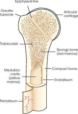
A tough, fibrous connective tissue called the periosteum covers all bony surfaces except the articular surfaces, which are covered by the articular cartilage. The tissue lining the medullary cavity of bones is called the endosteum. Bones contain various knoblike projections called tubercles and tuberosities, which are covered by the periosteum. Muscles, tendons, and ligaments attach to the periosteum at these projections. Blood vessels and nerves enter and exit the bone through the periosteum.
BONE VESSELS AND NERVES
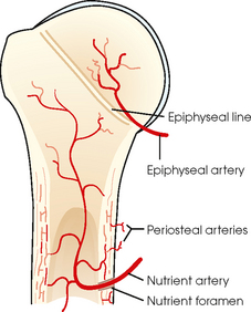
Bones are live organs and must receive a blood supply for nourishment or they die. Bones also contain a supply of nerves. Blood vessels and nerves enter and exit the bone at the same point, through openings called the foramina. Near the center of all long bones is an opening in the periosteum called the nutrient foramen. The nutrient artery of the bone passes into this opening and supplies the cancellous bone and marrow. The epiphyseal artery separately enters the ends of long bones to supply the area, and periosteal arteries enter at numerous points to supply the compact bone. Veins exiting the bones carry blood cells to the body (Fig. 3-14).
BONE DEVELOPMENT
Ossification is the term given to the development and formation of bones. Bones begin to develop in the 2nd month of embryonic life. Ossification occurs separately by two distinct processes: intermembranous ossification and endochondral ossification.
Intermembranous ossification
Bones that develop from fibrous membranes in the embryo produce the flat bones—bones of the skull, clavicles, mandible, and sternum. Before birth, these bones are not joined. As flat bones grow after birth, they join and form sutures. Other bones in this category merge and create the various joints of the skeleton.
Endochondral ossification
Bones created by endochondral ossification develop from hyaline cartilage in the embryo and produce the short, irregular, and long bones. Endochondral ossification occurs from two distinct centers of development called the primary and secondary centers of ossification.
Primary ossification
Primary ossification begins before birth and forms the entire bulk of the short and irregular bones. This process forms the long central shaft in long bones. During development only, the long shaft of the bone is called the diaphysis (Fig. 3-15, A).
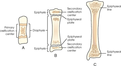
Secondary ossification
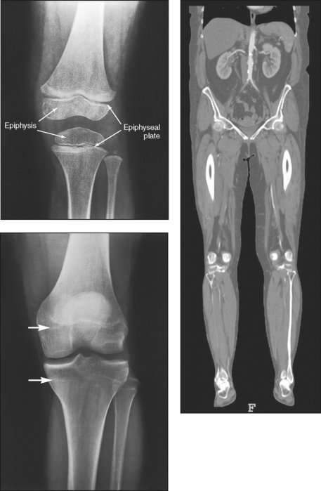
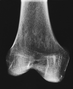
Secondary ossification occurs after birth when a separate bone begins to develop at both ends of each long bone. Each end is called the epiphysis (Fig. 3-15, B). At first, the diaphysis and epiphysis are distinctly separate. As growth occurs, a plate of cartilage called the epiphyseal plate develops between the two areas (Fig. 3-15, C). This plate is seen on long bone radiographs of all pediatric patients (Fig. 3-16, A). The epiphyseal plate is important radiographically because it is a common site of fractures in pediatric patients. Near age 21 years, full ossification occurs, and the two areas become completely joined; only a moderately visible epiphyseal line appears on the bone (Fig. 3-16, B).
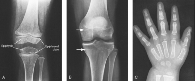
Fig. 3-16 A, Radiograph of a 6-year-old child. Epiphysis and epiphyseal plate shown on knee radiograph (arrows). B, Radiograph of same area in a 21-year-old adult. Full ossification has occurred, and only subtle epiphyseal lines are seen (arrows). C, PA radiograph of hand of a 2½-year-old child. Note early stages of ossification in epiphyses at proximal ends of phalanges and first metacarpal, distal ends of other metacarpals, and radius. (C, From Standring S: Gray’s anatomy, ed 40, New York, 2009, Churchill Livingstone.) Churchill Livingstone
CLASSIFICATION OF BONES
Bones are classified by shape, as follows (Fig. 3-17):
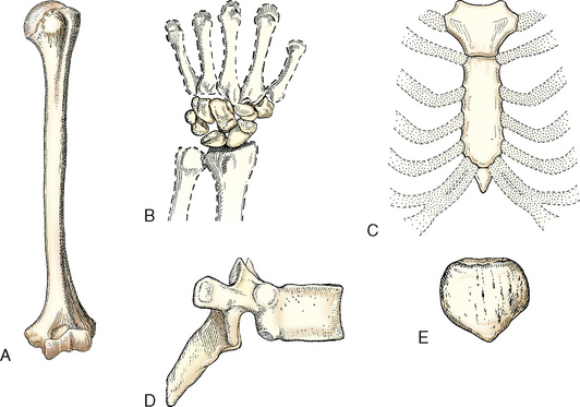
Fig. 3-17 Bones are classified by shape. A, Humerus is a long bone. B, Carpals of the wrist are short bones. C, Sternum is a flat bone. D, Vertebra is an irregular bone. E, Patella is a sesamoid bone.
Long bones
Long bones are found only in the limbs. They consist primarily of a long cylindric shaft called the body and two enlarged, rounded ends that contain a smooth, slippery articular surface. A layer of articular cartilage covers this surface. The ends of these bones all articulate with other long bones. The femur and humerus are typical long bones. The phalanges of the fingers and toes are also considered long bones. A primary function of long bones is to provide support.
Short bones
Short bones consist mainly of cancellous bone containing red marrow and have a thin outer layer of compact bone. The carpal bones of the wrist and the tarsal bones of the ankles are the only short bones. They are varied in shape and allow minimum flexibility of motion in a short distance.
Flat bones
Flat bones consist largely of two tables of compact bone. The narrow space between the inner and outer tables contains cancellous bone and red marrow, or diploë, as it is called in flat bones. The bones of the cranium, sternum, and scapula are examples of flat bones. The flat surfaces of these bones provide protection, and their broad surfaces allow muscle attachment.
Irregular bones
Irregular bones are so termed because their peculiar shapes and variety of forms do not place them in any other category. The vertebrae and the bones in the pelvis and face fall into this category. Similar to other bones, they have compact bone on the exterior and cancellous bone containing red marrow in the interior. Their shape serves many functions, including attachment for muscles, tendons, and ligaments, or they attach to other bones to create joints.
Sesamoid bones
Sesamoid bones are small and oval. They develop inside and beside tendons. Their precise role is not understood. Experts believe that they alter the direction of muscle pull and decrease friction. The largest sesamoid bone is the patella, or the kneecap. Other sesamoids are located beneath the first metatarsophalangeal articulation of the foot and on the palmar aspect of the thumb at the metacarpophalangeal joint of the hand. Two small but prominent sesamoids are located beneath the base of the large toe. Similar to all other bones, they can be fractured.
Arthrology
Arthrology is the study of the joints, or articulations between bones. Joints make it possible for bones to support the body, protect internal organs, and create movement. Various specialized articulations are necessary for these functions to occur.
The two classifications of joints described in anatomy books are functional and structural. Studying both classifications can be confusing. The most widely used and primary classification is the structural classification, which is used to describe all the joints in this atlas. This is also the classification recognized by Nomina Anatomica. For academic interest, a brief description of the functional classification is also provided.
FUNCTIONAL CLASSIFICATION
When joints are classified as functional, they are broken down into three classifications. These classifications are based on the mobility of the joint, as follows:
STRUCTURAL CLASSIFICATION
The structural classification of joints is based on the types of tissues that unite or bind the articulating bones. A thorough study of this classification is easier if radiographers first become familiar with the terminology and breakdown of the structural classification identified in Table 3-4.
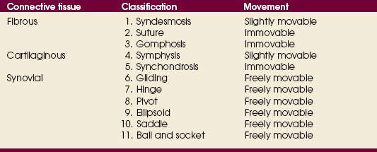
Structurally, joints are classified into three distinct groups on the basis of their connective tissues: fibrous, cartilaginous, and synovial. Within these three broad categories are the 11 specific types of joints. They are numbered in the text for easy reference to Table 3-4.
Fibrous joints
Fibrous joints do not have a joint cavity. They are united by various fibrous and connective tissues or ligaments. These are the strongest joints in the body because they are virtually immovable. The three types of fibrous joints are as follows:
1. Syndesmosis: An immovable joint or slightly movable joint united by sheets of fibrous tissue. The inferior tibiofibular joint is an example (Fig. 3-18, A).
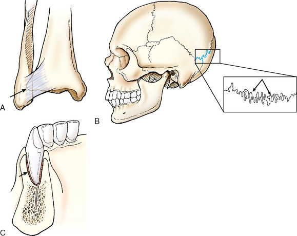
Fig. 3-18 Examples of three types of fibrous joints. A, Syndesmosis: Inferior tibiofibular joint. B, Suture: Sutures of skull. C, Gomphosis: Roots of teeth in alveolus.
2. Suture: An immovable joint occurring only in the skull. In this joint, the interlocking bones are held tightly together by strong connective tissues. The sutures of the skull are an example (Fig. 3-18, B).
3. Gomphosis: An immovable joint occurring only in the roots of the teeth. The roots of the teeth that lie in the alveolar sockets are held in place by fibrous periodontal ligaments (Fig. 3-18, C).
Cartilaginous joints
Cartilaginous joints are similar to fibrous joints in two ways: (1) They do not have a joint cavity, and (2) they are virtually immovable. Hyaline cartilage or fibrocartilage unites these joints. The two types of cartilaginous joints are as follows:
4. Symphysis: A slightly movable joint. The bones in this joint are separated by a pad of fibrocartilage. The ends of the bones contain hyaline cartilage. A symphysis joint is designed for strength and shock absorbency. The joint between the two pubic bones (pubic symphysis) is an example of a symphysis joint (Fig. 3-19, A). Another example of a symphysis joint is the joint between each vertebral body. These joints all contain a fibrocartilaginous pad or disk.
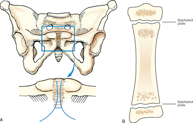
Fig. 3-19 Examples of two types of cartilaginous joints. A, Symphysis: Pubic symphysis. B, Synchondrosis: Epiphyseal plate found between epiphysis and diaphysis of growing long bones.
5. Synchondrosis: An immovable joint. This joint contains a rigid cartilage that unites two bones. An example is the epiphyseal plate found between the epiphysis and diaphysis of a growing long bone (Fig. 3-19, B). Before adulthood, these joints consist of rigid hyaline cartilage that unites two bones. When growth stops, the cartilage ossifies, making this type of joint a temporary joint.
Synovial joints
Synovial joints permit a wide range of motion, and they all are freely movable. These joints are the most complex joints in the body. Fig. 3-20 shows their distinguishing features.
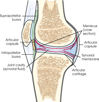
An articular capsule completely surrounds and enfolds all synovial joints to join the separate bones together. The outer layer of the capsule is called the fibrous capsule, and its fibrous tissue connects the capsule to the periosteum of the two bones. The synovial membrane, which is the inner layer, surrounds the entire joint to create the joint cavity. The membrane produces a thick, yellow, viscous fluid called synovial fluid. Synovial fluid lubricates the joint space to reduce friction between the bones. The ends of the adjacent bones are covered with articular cartilage. This smooth and slippery cartilage permits ease of motion. The two cartilages do not actually touch because they are separated by a thin layer of synovial membrane and fluid.
Some synovial joints contain a pad of fibrocartilage called the meniscus, which surrounds the joint. Specific menisci intrude into the joint from the capsular wall. They act as shock absorbers by conforming to and filling in the large gaps around the periphery of the bones. Some synovial joints also contain synovial fluid–filled sacs outside the main joint cavity, which are called the bursae. Bursae help reduce friction between skin and bones, tendons and bones, and muscles and bones. The menisci, bursae, and other joint structures can be visualized radiographically by injecting iodine-based contrast medium or air directly into the synovial cavity. This procedure, called arthrography, is detailed in Chapter 12.
The 6 synovial joints complete the 11 types of joints within the structural classification. They are listed in order of increasing movement. The most common name of each joint is identified, and the less frequently used name is given in parentheses.
6. Gliding (plane): Uniaxial movement. This is the simplest synovial joint. Joints of this type permit slight movement. They have flattened or slightly curved surfaces, and most glide slightly in only one axis. The intercarpal and intertarsal joints of the wrist and foot are examples of gliding joints (Fig. 3-21, A).
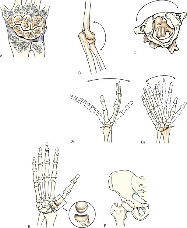
Fig. 3-21 Examples of six types of synovial joints. A, Gliding: Intercarpal joints of wrist. B, Hinge: Elbow joint. C, Pivot: Atlas and axis of cervical spine (viewed from above). D, Ellipsoid: Radiocarpal joint of wrist. E, Saddle: Carpometacarpal joint. F, Ball and socket: Hip joint.
7. Hinge (ginglymus): Uniaxial movement. A hinge joint permits only flexion and extension. The motion is similar to that of a door. The elbow, knee, and ankle are examples of this type of joint (Fig. 3-21, B).
8. Pivot (trochoid): Uniaxial movement. These joints allow only rotation around a single axis. A rounded or pointed surface of one bone articulates within a ring formed partially by the other bone. An example of this joint is the articulation of the atlas and axis of the cervical spine. The atlas rotates around the dens of the axis and allows the head to rotate to either side (Fig. 3-21, C).
9. Ellipsoid (condyloid): Biaxial movement, primary. An ellipsoid joint permits movement in two directions at right angles to each other. The radiocarpal joint of the wrist is an example. Flexion and extension occur along with abduction and adduction. Circumduction, a combination of both movements, can also occur (Fig. 3-21, D).
10. Saddle (sellar): biaxial movement. This joint permits movement in two axes, similar to the ellipsoid joint. The joint is so named because the articular surface of one bone is saddle-shaped and the articular surface of the other bone is shaped like a rider sitting in a saddle. The two saddlelike structures fit into each other. The carpometacarpal joint between the trapezium and the first metacarpal is the only saddle joint in the body. The face of each bone end has a concave and a convex aspect. The opposing bones are shaped in a manner that allows side-to-side and up-and-down movement (Fig. 3-21, E).
11. Ball and socket (spheroid): multiaxial movement. This joint permits movement in many axes, including flexion and extension, abduction and adduction, circumduction, and rotation. In a ball-and-socket joint, the round head of one bone rests within the cup-shaped depression of the other bone. The hip and shoulder are examples (Fig. 3-21, F).
Bone Markings and Features
The following anatomic terms are used to describe either processes or depressions on bones.
PROCESSES OR PROJECTIONS
Processes or projections extend beyond or project out from the main body of a bone and are designated by the following terms:
condyle rounded process at an articular extremity
coracoid or coronoid beaklike or crownlike process
epicondyle projection above a condyle
facet small, smooth-surfaced process for articulation with another structure
head expanded end of a long bone
horn hornlike process on a bone
line less prominent ridge than a crest; a linear elevation
protuberance projecting part or prominence
trochanter either of two large, rounded, and elevated processes (greater or major and lesser or minor) located at junction of neck and shaft of femur
DEPRESSIONS
Depressions are hollow or depressed areas and are described by the following terms:
foramen hole in a bone for transmission of blood vessels and nerves
fossa pit, fovea, or hollow space
meatus tubelike passageway running within a bone
notch indentation into border of a bone
sinus recess, groove, cavity, or hollow space, such as (1) recess or groove in bone, as used to designate a channel for venous blood on inner surface of cranium; (2) air cavity in bone or hollow space in other tissue (used to designate a hollow space within a bone, as in paranasal sinuses); or (3) fistula or suppurating channel in soft tissues
Fractures
A fracture is a break in the bone. Fractures are classified according to the nature of the break. Several general terms can pertain to them:
closed fracture that does not break through the skin
displaced serious fracture in which bones are not in anatomic alignment
nondisplaced fracture in which bone retains its normal alignment
open serious fracture in which broken bone or bones project through the skin
Common classifications of fractures are listed as follows and identified in Fig. 3-22:
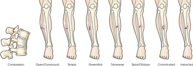
Many fractures fall into more than one category. A fracture could be spiral, closed, and nondisplaced.
Anatomic Relationship Terms
Various terms are used to describe the relationship of parts of the body in the anatomic position. Radiographers should be thoroughly familiar with these terms, which are commonly used in clinical practice. Most of the following positioning and anatomic terms are paired as opposites. Fig. 3-23 illustrates two commonly used sets of terms.
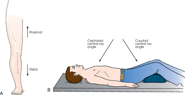
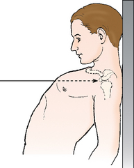
Fig. 3-23 A, Use of common radiology terms proximal and distal. B, Use of common radiology terms caudad angle and cephalad angle.
anterior (ventral) refers to forward or front part of body or forward part of an organ
posterior (dorsal) refers to back part of body or organ (note, however, that the superior surface of the foot is referred to as the dorsal surface)
caudad refers to parts away from the head of the body
cephalad refers to parts toward the head of the body
inferior refers to nearer the feet or situated below
superior refers to nearer the head or situated above
central refers to middle area or main part of an organ
peripheral refers to parts at or near the surface, edge, or outside of another body part
contralateral refers to part or parts on the opposite side of body
ipsilateral refers to part or parts on the same side of body
lateral refers to parts away from the median plane of body or away from the middle of another body part to the right or left
medial refers to parts toward the median plane of body or toward the middle of another body part
deep refers to parts far from the surface
superficial refers to parts near the skin or surface
distal refers to parts farthest from the point of attachment, point of reference, origin, or beginning; away from center of body
proximal refers to parts nearer the point of attachment, point of reference, origin, or beginning; toward the center of body
external refers to parts outside an organ or on the outside of body
internal refers to parts within or on the inside of an organ
parietal refers to the wall or lining of a body cavity
visceral refers to the covering of an organ
dorsum refers to the top or anterior surface of the foot or to the back or posterior surface of the hand
Radiographic Positioning Terminology
Radiography is the process of recording an image of a body part using one or more types of IRs (cassette/film, cassette/phosphor plate, or fluoroscopic screen/TV). The terminology used to position the patient and to obtain the radiograph was developed through convention. Attempts to analyze the usage often lead to confusion because the manner in which the terms are used does not follow one specific rule. During the preparation of this chapter, contact was maintained with the American Registry of Radiologic Technologists (ARRT) and the Canadian Association of Medical Radiation Technologists (CAMRT). The ARRT first distributed the “Standard Terminology for Positioning and Projection” in 19781; it has not been substantially revised since initial distribution.2 Despite its title, the ARRT document did not actually define selected positioning terms.3 Terms not defined by the ARRT are defined in this atlas.
Approval of Canadian positioning terminology is the responsibility of the CAMRT Radiography Council on Education. This council provided information for the development of this chapter and clearly identified the terminology differences between the United States and Canada.4
The terminology used by the ARRT and CAMRT is consistent overall with that used in this atlas. The only difference is that the term view is commonly used in Canada for some projections and positions.
The following are the four positioning terms most commonly used in radiology:
PROJECTION
The term projection is defined as the path of the central ray as it exits the x-ray tube and goes through the patient to the IR. Most projections are defined by the entrance and exit points in the body and are based on the anatomic position. When the central ray enters anywhere in the front (anterior) surface of the body and exits the back (posterior), an anteroposterior (AP) projection is obtained. Regardless of which body position the patient is in (e.g., supine, prone, upright), if the central ray enters the anterior body surface and exits the posterior body surface, the projection is termed an AP projection (Fig. 3-24).
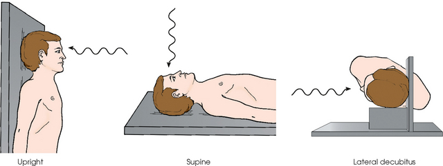
Fig. 3-24 Patient’s head placed in upright, supine, and lateral decubitus positions for a radiograph. All three body positions produce AP projection of skull.
Projections can also be defined by the relationship formed between the central ray and the body as the central ray passes through the entire body or body part. Examples include the axial and tangential projections.
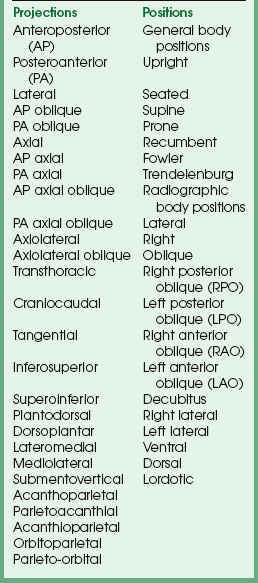
All radiographic examinations described in this atlas are standardized and titled by their x-ray projection. The x-ray projection accurately and concisely defines each image produced in radiography. A complete list of the projection terms used in radiology is provided in Box 3-2. The essential radiographic projections follow.
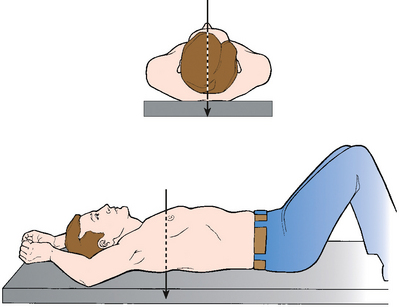
Anteroposterior projection
In Fig. 3-25, a perpendicular central ray enters the anterior body surface and exits the posterior body surface. This is an AP projection. The patient is shown in the supine or dorsal recumbent body position. AP projections can also be achieved with upright, seated, or lateral decubitus positions.
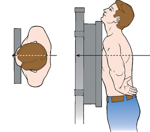
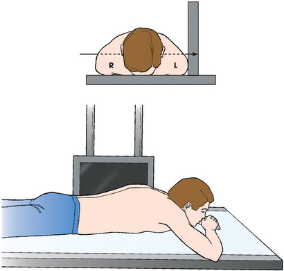
Posteroanterior projection
In Fig. 3-26, a perpendicular central ray is shown entering the posterior body surface and exiting the anterior body surface. This illustrates a posteroanterior (PA) projection with the patient in the upright body position. PA projections can also be achieved with seated, prone (ventral recumbent), and lateral decubitus positions.
Axial projection
In an axial projection (Fig. 3-27), there is longitudinal angulation of the central ray with the long axis of the body or a specific body part. This angulation is based on the anatomic position and is most often produced by angling the central ray cephalad or caudad. The longitudinal angulation in some examinations is achieved by angling the entire body or body part while maintaining the central ray perpendicular to the IR.
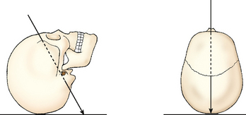
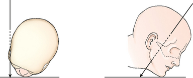
Fig. 3-27 AP axial projection of skull. Central ray enters anterior aspect at an angle and exits posterior aspect.
The term axial, as used in this atlas, refers to all projections in which the longitudinal angulation between the central ray and the long axis of the body part is 10 degrees or more. When a range of central ray angles (e.g., 5 to 15 degrees) is recommended for a given projection, the term axial is used because the angulation could exceed 10 degrees. Axial projections are used in a wide variety of examinations and can be obtained with the patient in virtually any body position.
Tangential projection
Occasionally the central ray is directed toward the outer margin of a curved body surface to profile a body part just under the surface and project it free of superimposition. This is called a tangential projection because of the tangential relationship formed between the central ray and the entire body or body part (Fig. 3-28).
Lateral projection
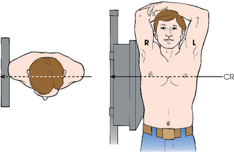
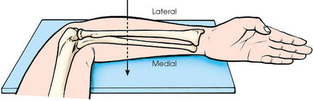
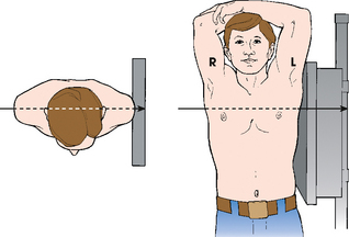
For a lateral projection, a perpendicular central ray enters one side of the body or body part, passes transversely along the coronal plane, and exits on the opposite side. Lateral projections can enter from either side of the body or body part as needed for the examination. This can be determined by the patient’s condition or ordered by the physician. When a lateral projection is used for head, chest, or abdominal radiography, the direction of the central ray is described with reference to the associated radiographic position. A left lateral position or right lateral position specifies the side of the body closest to the IR and corresponds with the side exited by the central ray (Fig. 3-29). For a right lateral position, the central ray enters the left side of the body and exits the right side (see Fig. 3-29). Lateral projections of the limbs are clarified further by the terms lateromedial or mediolateral to indicate the sides entered and exited by the central ray (Fig. 3-30). The transthoracic projection is a unique lateral projection used for shoulder radiography and is described in Chapter 5.
Oblique projection
During an oblique projection, the central ray enters the body or body part from a side angle following an oblique plane. Oblique projections may enter from either side of the body and from anterior or posterior surfaces. If the central ray enters the anterior surface and exits the opposite posterior surface, it is an AP oblique projection; if it enters the posterior surface and exits anteriorly, it is a PA oblique projection (Fig. 3-31).
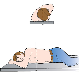
Fig. 3-31 PA oblique projection of chest. Central ray enters posterior aspect of body (even though it is rotated) and exits anterior aspect.
Most oblique projections are achieved by rotating the patient with the central ray perpendicular to the IR. As in the lateral projection, the direction of the central ray for oblique projections is described with reference to the associated radiographic position. A right posterior oblique position (RPO) places the right posterior surface of the body closest to the IR and corresponds with an AP oblique projection exiting through the same side. This relationship is discussed later. Oblique projections can also be achieved for some examinations by angling the central ray diagonally along the horizontal plane rather than rotating the patient.
Complex projections
For additional clarity, projections may be defined by entrance and exit points and by the central ray relationship to the body at the same time. In the PA axial projection, the central ray enters the posterior body surface and exits the anterior body surface following an axial or angled trajectory relative to the entire body or body part. Axiolateral projections also use angulations of the central ray, but the ray enters and exits through lateral surfaces of the entire body or body part.
True projections
The term true (true AP, true PA, and true lateral)1 is often used in clinical practice. True is used specifically to indicate that the body part must be placed exactly in the anatomic position.
A true AP or PA projection is obtained when the central ray is perpendicular to the coronal plane and parallel to the sagittal plane. A true lateral projection is obtained when the central ray is parallel to the normal plane and perpendicular to the sagittal plane. When a body part is rotated for an AP or PA oblique projection, a true AP or PA projection cannot be obtained. In this atlas, the term true is used only when the body part is placed in the anatomic position.
POSITION
The term position is used in two ways in radiology. One way identifies the overall posture of the patient or the general body position. The patient may be described as upright, seated, or supine. The second use of position refers to the specific placement of the body part in relation to the radiographic table or IR during imaging. This is the radiographic position and may be a right lateral, left anterior oblique, or other position depending on the examination and anatomy of interest. A list of all general body positions and radiographic positions is provided in Box 3-2.
During radiography, general body positions are combined with radiographic positions to produce the appropriate image. For clarification of the positioning for an examination, it is often necessary to include references to both because a particular radiographic position, such as right lateral, can be achieved in several general body positions (e.g., upright, supine, lateral recumbent) with differing image outcomes. Specific descriptions of general body positions and radiographic positions follow.
General body positions
The following list describes the general body positions. All are commonly used in radiography practice.
upright erect or marked by a vertical position (see Fig. 3-26)
seated upright position in which the patient is sitting on a chair or stool
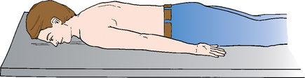
recumbent general term referring to lying down in any position, such as dorsal recumbent (Fig. 3-32), ventral recumbent (Fig. 3-33), or lateral recumbent (Fig. 3-34)
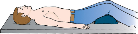
Fig. 3-32 Supine position of body, also termed dorsal recumbent position. The patient’s knees are flexed for comfort.
supine lying on the back (see Fig. 3-32)
prone lying face down (see Fig. 3-33)
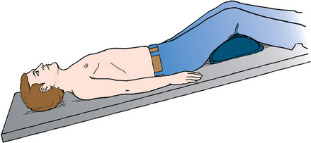
Trendelenburg position supine position with head tilted downward (Fig. 3-35)
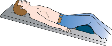
Fowler position supine position with head higher than the feet (Fig. 3-36)
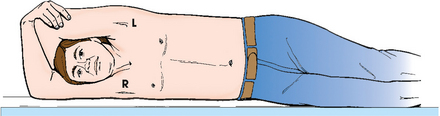
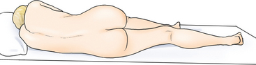
Sims position recumbent position with the patient lying on the left anterior side (semiprone) with left leg extended and right knee and thigh partially flexed (Fig. 3-37)
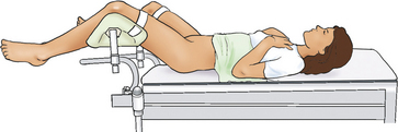
lithotomy position supine position with knees and hip flexed and thighs abducted and rotated externally, supported by ankle or knee supports (Fig. 3-38)
Lateral position
Lateral radiographic positions are always named according to the side of the patient that is placed closest to the IR (Figs. 3-39 and 3-40). In this atlas, the right or left lateral positions are indicated as subheadings for all lateral x-ray projections of the head, chest, and abdomen in which either the left or the right side of the patient is placed adjacent to the IR. The specific side selected depends on the condition of the patient, the anatomic structure of clinical interest, and the purpose of the examination. In Figs. 3-39 and 3-40, the x-ray projection for the positions indicated is lateral projection.
Oblique position
An oblique radiographic position is achieved when the entire body or body part is rotated so that the coronal plane is not parallel with the radiographic table or IR. The angle of oblique rotation varies with the examination and structures to be shown. In this atlas, an angle is specified for each oblique position (e.g., rotated 45 degrees from the prone position).
Oblique positions, similar to lateral positions, are always named according to the side of the patient that is placed closest to the IR. In Fig. 3-41, the patient is rotated with the right anterior body surface in contact with the radiographic table. This is a right anterior oblique (RAO) position because the right side of the anterior body surface is closest to the IR. Fig. 3-42 shows the patient placed in a left anterior oblique (LAO) position.
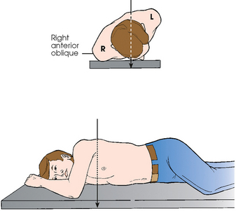
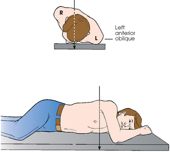
The relationship between oblique position and oblique projection can be summarized simply. Anterior oblique positions result in PA oblique projections as shown in Figs. 3-41 and 3-42. Similarly, posterior oblique positions result in AP oblique projections as illustrated in Figs. 3-43 and 3-44.
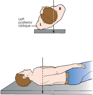
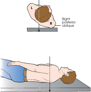
The oblique positioning terminology used in this atlas has been standardized using RAO and LAO or RPO and LPO positions along with the appropriate PA or AP oblique projection. For oblique positions of the limbs, the terms medial rotation and lateral rotation have been standardized to designate the direction in which the limbs have been turned from the anatomic position (Fig. 3-45).
Decubitus position
In radiographic positioning terminology, the term decubitus indicates that the patient is lying down and that the central ray is horizontal and parallel with the floor. Three primary decubitus positions are named according to the body surface on which the patient is lying: lateral decubitus (left or right), dorsal decubitus, and ventral decubitus. Of these, the lateral decubitus position is used most often to show the presence of air-fluid levels or free air in the chest and abdomen.
In Fig. 3-46, the patient is placed in the left lateral decubitus radiographic position with the back (posterior surface) closest to the IR. In this position, a horizontal central ray provides an AP projection. Fig. 3-46 is accurately described as an AP projection with the body in the left lateral decubitus position. Alternatively, the patient may be placed with the front of the body (anterior surface) facing the IR, resulting in a PA projection. This would be correctly described as a PA projection of the body in the left lateral decubitus position. Right lateral decubitus positions may be necessary with AP or PA projections, depending on the examination.
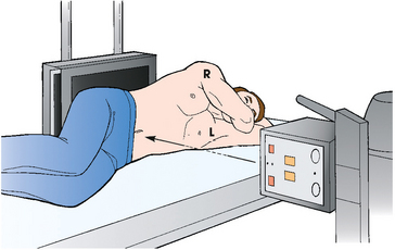
Fig. 3-46 Left lateral decubitus radiographic position of abdomen results in AP projection. Note horizontal orientation of central ray.
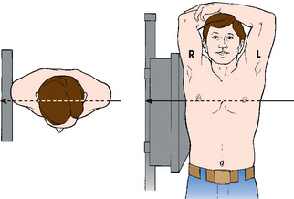
In Fig. 3-47, the patient is shown in a dorsal decubitus radiographic position with one side of the body next to the IR. The horizontal central ray provides a lateral projection. This is correctly described as a lateral projection with the patient placed in the dorsal decubitus position. Either side may face the IR, depending on the examination or the patient’s condition.
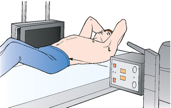
Fig. 3-47 Right dorsal decubitus radiographic position of abdomen results in right lateral projection. Note horizontal orientation of central ray.
The ventral decubitus radiographic position (Fig. 3-48) also places a side of the body adjacent to the IR, resulting in a lateral projection. Similar to the earlier examples, the accurate terminology is lateral projection with the patient in the ventral decubitus position. Either side may face the IR.
Lordotic position
The lordotic position is achieved by having the patient lean backward while in the upright body position so that only the shoulders are in contact with the IR (Fig. 3-49). An angulation forms between the central ray and the long axis of the upper body, producing an AP axial projection. This position is used for the visualization of pulmonary apices (see Chapter 10) and clavicles (see Chapter 5).
Note to educators, students, and clinicians
In clinical practice, the terms position and projection are often incorrectly used. These are two distinct terms that should not be interchanged. Incorrect use leads to confusion for the student who is attempting to learn the correct terminology of the profession. Educators and clinicians are encouraged to use the term projection generally when describing any examination performed. The word projection is the only term that accurately describes how the body part is being examined. The term position should be used only when referring to the placement of the patient’s body. A correct example is, “We are going to perform a PA projection of the chest with the patient in the upright position.”
VIEW
The term view is used to describe the body part as seen by the IR. Use of this term is restricted to the general discussion of a finished radiograph or image. View and projection are exact opposites. For many years, view and projection were often used interchangeably, which led to confusion. In the United States, projection has replaced view as the preferred terminology for describing radiographic images. In Canada, view remains an acceptable positioning term. For consistency, this atlas refers to all views as images or radiographs.
METHOD
Some radiographic projections and procedures are named after individuals (e.g., Waters, Towne) in recognition of their development of a method to show a specific anatomic part. Method, which was first described in the fifth edition of this atlas, describes the specific radiographic projection that the individual developed. The majority of methods are named after an individual, however a few are for unique projections. The method specifies the x-ray projection and body position, and it may include specific items such as IR, CR, or other unique aspects. In this atlas, standard projection terminology is used first, and a named method is listed secondarily (e.g., PA axial projection; Towne method). The ARRT and CAMRT use the standard anatomic projection terminology and list the originator in parentheses.
Body Movement Terminology
The following terms are used to describe movement related to the limbs. These terms are often used in positioning descriptions and in the patient history provided to the radiographer by the referring physician. They must be studied thoroughly.
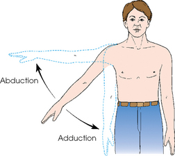
abduct or abduction movement of a part away from the central axis of the body or body part
adduct or adduction movement of a part toward the central axis of the body or body part (Fig. 3-50)
extension straightening of a joint; when both elements of the joint are in the anatomic position; normal position of a joint (Fig. 3-51)
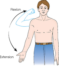
flexion act of bending a joint; opposite of extension (Fig. 3-52)
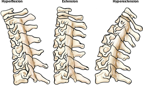
hyperextension forced or excessive extension of a limb or joints
hyperflexion forced overflexion of a limb or joints (see Fig. 3-52)
evert/eversion outward turning of the foot at the ankle
invert/inversion inward turning of the foot at the ankle (Fig. 3-53)
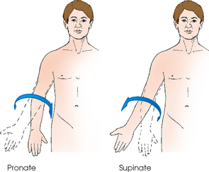
pronate/pronation rotation of the forearm so that the palm is down
supinate/supination rotation of the forearm so that the palm is up (in the anatomic position) (Fig. 3-54)
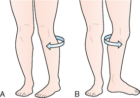
rotate/rotation turning or rotating of body or a body part around its axis (Fig. 3-55, A); rotation of a limb is either medial (toward the midline of the body from the anatomic position [Fig. 3-55, B]) or lateral (away from the midline of the body from the anatomic position [Fig. 3-55, C])
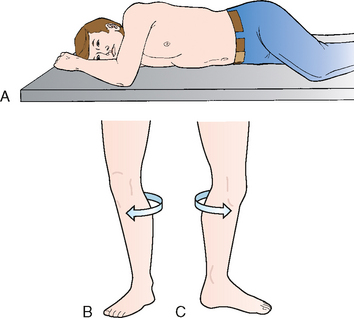
Fig. 3-55 A, Rotation of chest and abdomen. The patient’s arm and knee are flexed for comfort. B, Medial rotation of left leg. C, Lateral rotation of left leg.
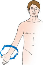
circumduction circular movement of a limb (Fig. 3-56)
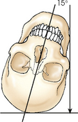
tilt tipping or slanting a body part slightly; tilt is in relation to the long axis of the body (Fig. 3-57)
deviation turning away from the regular standard or course (Fig. 3-58)
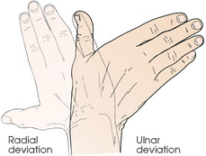
Fig. 3-58 Radial deviation of hand (turned to radial side) and ulnar deviation (turned to ulnar side).
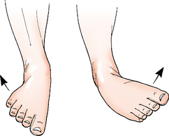
dorsiflexion flexion or bending the foot toward the leg (Fig. 3-59)
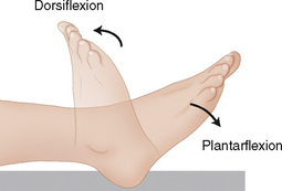
plantar flexion flexion or bending the foot downward toward the sole (see Fig. 3-59)
Medical Terminology
Single and plural word endings for common Greek and Latin nouns are presented in Table 3-5. Single and plural word forms are often confused. Examples of commonly misused word forms are listed in Table 3-6; the singular form generally is used when the plural form is intended.
TABLE 3-5
Greek and Latin nouns: common singular and plural forms
| Singular | Plural | Examples: singular—plural |
| -a | -ae | maxilla—maxillae |
| -ex | -ces | apex—apices |
| -is | -es | diagnosis—diagnoses |
| -ix | -ces | appendix—appendices |
| -ma | -mata | condyloma—condylomata |
| -on | -a | ganglion—ganglia |
| -um | -a | antrum—antra |
| -us | -i | ramus—rami |
TABLE 3-6
Frequently misused single and plural word forms
| Singular | Plural |
| adnexus | adnexa |
| alveolus | alveoli |
| Areola | areolae |
| bronchus | bronchi |
| Bursa | bursae |
| calculus | calculi |
| Coax | coxae |
| diagnosis | diagnoses |
| diverticulum | diverticula |
| Fossa | fossae |
| Gingival | gingivae |
| haustrum | haustra |
| Hilum | hila |
| Ilium | ilia |
| Labium | labia |
| Lamina | laminae |
| Lumen | lumina |
| mediastinum | mediastina |
| medulla | medullae |
| meninx | meninges |
| meniscus | menisci |
| metastasis | metastases |
| mucosa | mucosae |
| omentum | omenta |
| paralysis | paralyses |
| plexus | plexi |
| pleura | pleurae |
| pneumothorax | pneumothoraces |
| ramus | rami |
| ruga | rugae |
| sulcus | sulci |
| thrombus | thrombi |
| vertebra | vertebrae |
| viscus | viscera |
See Addendum A for a summary of all abbreviations used in Volume 1.
1Mills WR: The relation of bodily habitus to visceral form, position, tonus, and motility, AJR 4:155, 1917.
1ARRT educator’s handbook, ed 3, 1990, ARRT.
2ARRT educator guide, Spring 2010.
3ARRT, personal communication and permission, May 2006.
4CAMRT, Radiography Council on Education, personal communication, July 1993.
1Bontrager KL: Textbook of radiographic positioning, ed 7, St Louis, 2009, Mosby.