UPPER LIMB
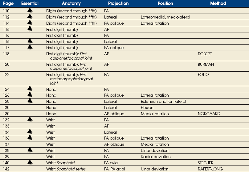
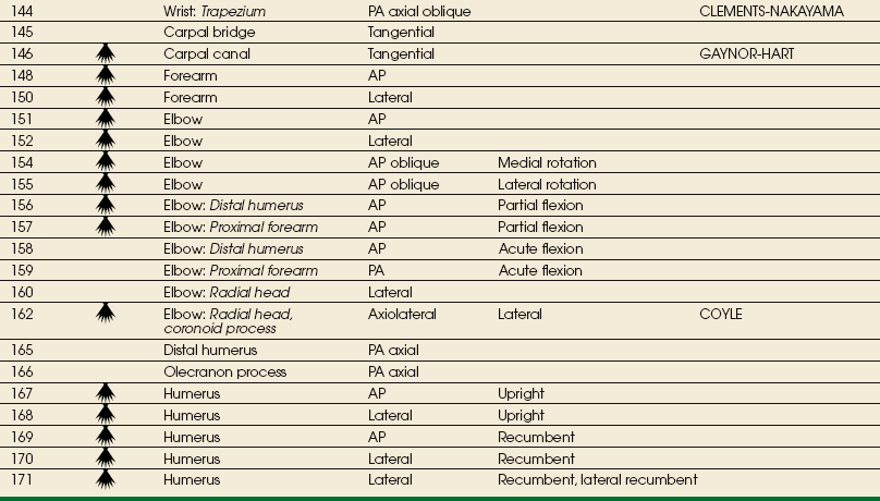
SUMMARY OF PROJECTIONS
ANATOMY
Anatomists divide the bones of the upper limbs, or extremities, into the following main groups:
The proximal arm and shoulder girdle are discussed in Chapter 5.
Hand
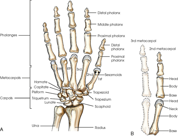
The hand consists of 27 bones, which are subdivided into the following groups:
• Phalanges: Bones of the digits (fingers and thumb)
• Metacarpals: Bones of the palm
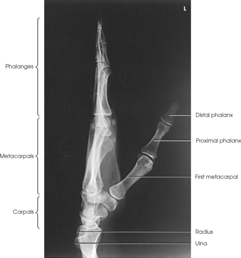
• Carpals: Bones of the wrist (Fig. 4-1)
DIGITS
The five digits are described by numbers and names; however, description by number is the more correct practice. Beginning at the lateral, or thumb, side of the hand, the numbers and names are as follows:
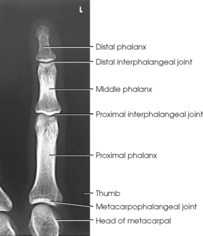
The digits contain 14 phalanges (phalanx, singular), which are long bones that consist of a cylindric body and articular ends. Nine phalanges have two articular ends. The first digit has two phalanges—the proximal and distal. The other digits have three phalanges—the proximal, middle, and distal. The proximal phalanges are the closest to the palm, and the distal phalanges are the farthest from the palm. The distal phalanges are small and flattened, with a roughened rim around their distal anterior end; this gives them a spatulalike appearance. Each phalanx has a head, body, and base.
METACARPALS
Five metacarpals, which are cylindric in shape and slightly concave anteriorly, form the palm of the hand (see Fig. 4-1). They are long bones consisting of a body and two articular ends—the head distally and the base proximally. The area below the head is the neck where fractures often occur. The first metacarpal contains two small sesamoid bones on its palmar aspect below the neck (see Fig. 4-1). A single sesamoid is often seen at this same level on the second metacarpal. The metacarpal heads, commonly known as the knuckles, are visible on the dorsal hand in flexion. The metacarpals are also numbered 1 to 5, beginning from the lateral side of the hand.
WRIST
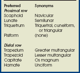
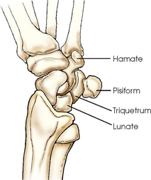
The wrist has eight carpal bones, which are fitted closely together and arranged in two horizontal rows (see Fig. 4-1). The carpals are classified as short bones and are composed largely of cancellous tissue with an outer layer of compact bony tissue. These bones, with one exception, have two or three names; this atlas uses the preferred terms (see box). The proximal row of carpals, which is nearest the forearm, contains the scaphoid, lunate, triquetrum, and pisiform. The distal row includes the trapezium, trapezoid, capitate, and hamate.
Each carpal contains identifying characteristics. Beginning at the proximal row of carpals on the lateral side, the scaphoid, the largest bone in the proximal carpal row, has a tubercle on the anterior and lateral aspect for muscle attachment and is palpable near the base of the thumb. The lunate articulates with the radius proximally and is easy to recognize because of its crescent shape. The triquetrum is roughly pyramidal and articulates anteriorly with the hamate. The pisiform is a pea-shaped bone situated anterior to the triquetrum and is easily palpated.
Beginning at the distal row of carpals on the lateral side, the trapezium has a tubercle and groove on the anterior surface. The tubercles of the trapezium and scaphoid constitute the lateral margin of the carpal groove. The trapezoid has a smaller surface anteriorly than posteriorly. The capitate articulates with the base of the third metacarpal and is the largest and most centrally located carpal. The wedge-shaped hamate exhibits the prominent hook of hamate, which is located on the anterior surface. The hamate and the pisiform form the medial margin of the carpal groove.
A triangular depression is located on the posterior surface of the wrist and is visible when the thumb is abducted and extended. This depression, known as the anatomic snuffbox, is formed by the tendons of the two major muscles of the thumb. The anatomic snuffbox overlies the scaphoid bone and the radial artery, which carries blood to the dorsum of the hand. Tenderness in the snuffbox area is a clinical sign suggesting fracture of the scaphoid—the most commonly fractured carpal bone.
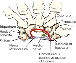
CARPAL SULCUS
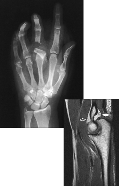
The anterior or palmar surface of the wrist is concave from side to side and forms the carpal sulcus (Figs. 4-2 and 4-3). The flexor retinaculum, a strong fibrous band, attaches medially to the pisiform and hook of hamate and laterally to the tubercles of the scaphoid and trapezium. The carpal tunnel is the passageway created between the carpal sulcus and flexor retinaculum. The median nerve and the flexor tendons pass through the carpal canal. Carpal tunnel syndrome results from compression of the median nerve inside the carpal tunnel.
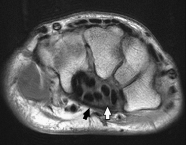
Fig. 4-2 Axial MRI of wrist. Bones in same position as in Fig. 4-3. Note arched position of carpal bones and carpal sulcus protecting tendons of fingers (black circles within sulcus) and median nerve (white arrow). Flexor retinaculum (black arrow) is also seen.
Forearm
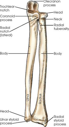
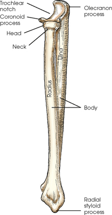
The forearm contains two bones that lie parallel to each other—the radius and ulna. Similar to other long bones, they have a body and two articular extremities. The radius is located on the lateral side of the forearm, and the ulna is located on the medial side (Figs. 4-4 and 4-5).
ULNA
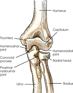
The body of the ulna is long and slender and tapers inferiorly. The upper portion of the ulna is large and presents two beaklike processes and concave depressions (Fig. 4-6). The proximal process, or olecranon process, concaves anteriorly and slightly inferiorly and forms the proximal portion of the trochlear notch. The more distal coronoid process projects anteriorly from the anterior surface of the body and curves slightly superiorly. The process is triangular and forms the lower portion of the trochlear notch. A depression called the radial notch is located on the lateral aspect of the coronoid process.
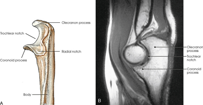
Fig. 4-6 A, Radial aspect of left proximal ulna. B, Sagittal MRI of elbow joint showing trochlear notch surrounding trochlea of humerus. (B, Modified from Kelley LL, Petersen CM: Sectional anatomy for imaging professionals, ed 2, St Louis, 2007, Mosby.)
The distal end of the ulna includes a rounded process on its lateral side called the head and a narrower conic projection on the posteromedial side called the ulnar styloid process. An articular disk separates the head of the ulna from the wrist joint.
RADIUS
The proximal end of the radius is small and presents a flat disklike head above a constricted area called the neck. Just inferior to the neck on the medial side of the body of the radius is a roughened process called the radial tuberosity. The distal end of the radius is broad and flattened and has a conic projection on its lateral surface called the radial styloid process.
Arm
The arm has one bone called the humerus, which consists of a body and two articular ends (Fig. 4-7, A and B). The proximal part of the humerus articulates with the shoulder girdle and is described further in Chapter 5. The distal humerus is broad and flattened and presents numerous processes and depressions.
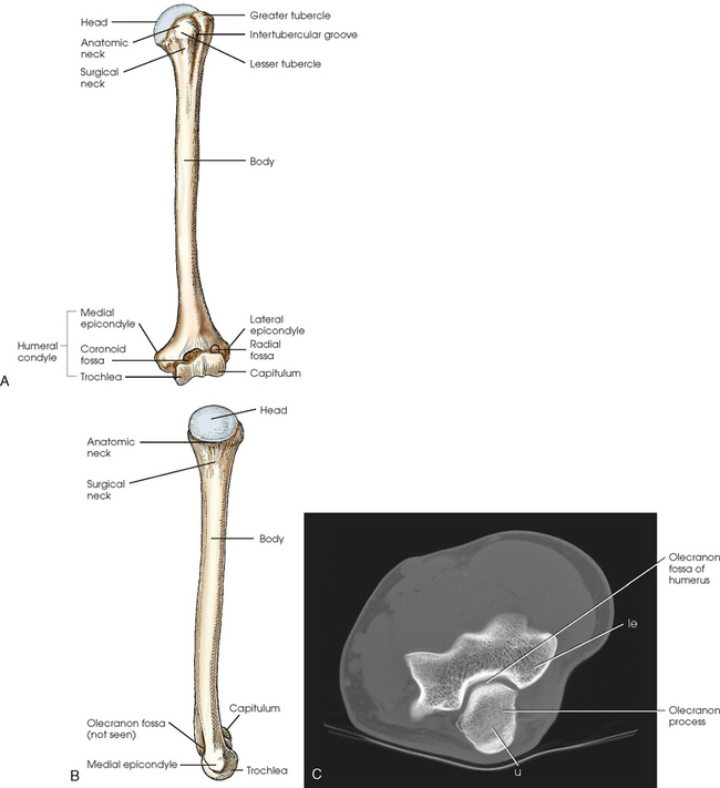
Fig. 4-7 A, Anterior aspect of left humerus. B, Medial aspect of left humerus. C, Axial CT scan of elbow. le, lateral epicondyle; u, ulna.
The entire distal end of the humerus is called the humeral condyle and includes two smooth elevations for articulation with the bones of the forearm—the trochlea on the medial side and the capitulum on the lateral side. The medial and lateral epicondyles are superior to the condyle and easily palpated. On the anterior surface superior to the trochlea, a shallow depression called the coronoid fossa receives the coronoid process when the elbow is flexed. The relatively small radial fossa, which receives the radial head when the elbow is flexed, is located lateral to the coronoid fossa and proximal to the capitulum. The olecranon fossa is a deep depression found immediately behind the coronoid fossa on the posterior surface and accommodates the olecranon process when the elbow is extended (Fig. 4-7, C).
The proximal end of the humerus contains the head, which is large, smooth, and rounded and lies in an oblique plane on the superomedial side. Just below the head, lying in the same oblique plane, is the narrow, constricted anatomic neck. The constriction of the body just below the tubercles is called the surgical neck, which is the site of many fractures.
The lesser tubercle is situated on the anterior surface of the bone immediately below the anatomic neck. The tendon of the subscapularis muscle inserts at the lesser tubercle. The greater tubercle is located on the lateral surface of the bone just below the anatomic neck and is separated from the lesser tubercle by a deep depression called the intertubercular groove.
Upper Limb Articulations
Table 4-1 contains a summary of the joints of the upper limb. A detailed description of the upper limb articulations follows.
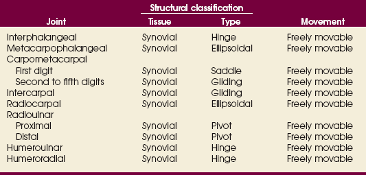
The interphalangeal (IP) articulations between the phalanges are synovial hinge type and allow only flexion and extension (Fig. 4-8). The IP joints are named by location and are differentiated as either proximal interphalangeal (PIP) or distal interphalangeal (DIP), by the digit number, and by right or left hand (e.g., the PIP articulation of the fourth digit of the left hand) (Fig. 4-9, A and B). Because the first digit has only two phalanges, the joint between the two phalanges is simply called the IP joint.
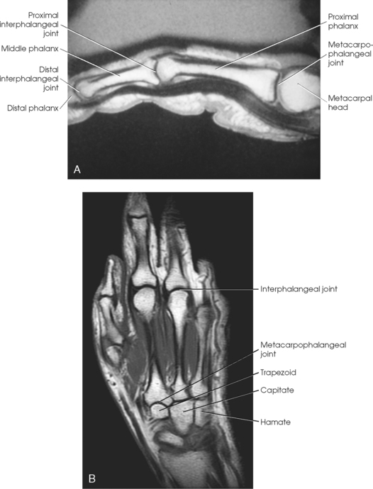
Fig. 4-8 A, Sagittal MRI of finger showing IP and MCP joints. B, Coronal MRI of hand and wrist showing same joints.
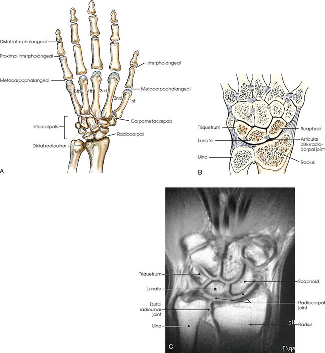
Fig. 4-9 A, Articulations of hand and wrist. B, Radiocarpal articulation formed by scaphoid, lunate, and triquetrum with radius. C, Coronal MRI of wrist showing bones and joints of wrist.
The metacarpals articulate with the phalanges at their distal ends and the carpals at their proximal ends. The metacarpophalangeal (MCP) articulations are synovial ellipsoidal joints and have the movements of flexion, extension, abduction, adduction, and circumduction. Because of the less convex and wider surface of the MCP joint of the thumb, only limited abduction and adduction are possible.
The carpals articulate with each other, the metacarpals, and the radius of the forearm. In the carpometacarpal (CMC) articulations, the first metacarpal and trapezium form a synovial saddle joint, which permits the thumb to oppose the fingers (touch the fingertips). The articulations between the second, third, fourth, and fifth metacarpals and the trapezoid, capitate, and hamate form synovial gliding joints. The intercarpal articulations are also synovial gliding joints. The articulations between the lunate and scaphoid form a gliding joint. The radiocarpal articulation is a synovial ellipsoidal type. This joint is formed by the articulation of the scaphoid, lunate, and triquetrum, with the radius and the articular disk just distal to the ulna (Fig. 4-9, C).
The distal and proximal radioulnar articulations are synovial pivot joints. The distal ulna articulates with the ulnar notch of the distal radius. The proximal head of the radius articulates with the radial notch of the ulna at the medial side. The movements of supination and pronation of the forearm and hand largely result from the combined rotary action of these two joints. In pronation, the radius turns medially and crosses over the ulna at its upper third, and the ulna makes a slight counterrotation that rotates the humerus medially.
The elbow joint proper includes the proximal radioulnar articulation and the articulations between the humerus and the radius and ulna. The three joints are enclosed in a common capsule. The trochlea of the humerus articulates with the ulna at the trochlear notch. The capitulum of the humerus articulates with the flattened head of the radius. The humeroulnar and humeroradial articulations form a synovial hinge joint and allow only flexion and extension movement (Figs. 4-10 and 4-11, A). The proximal humerus and its articulations are described with the shoulder girdle in Chapter 5.
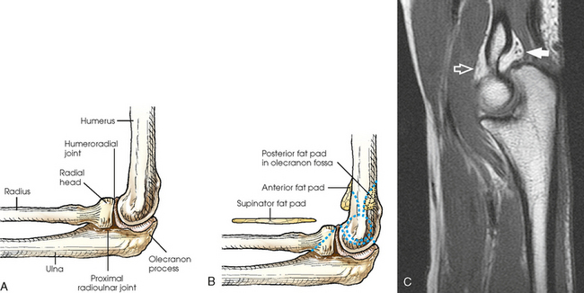
Fat Pads
The three areas of fat1,2 associated with the elbow joint can be visualized only in the lateral projection (Fig. 4-11, B and C). The posterior fat pad covers the largest area and lies within the olecranon fossa of the posterior humerus. The superimposed coronoid and radial fat pads, which lie in the coronoid and radial fossae of the anterior humerus, form the anterior fat pad. The supinator fat pad is positioned anterior to and parallel with the anterior aspect of the proximal radius.
When the elbow is flexed 90 degrees for the lateral projection, only the anterior and supinator fat pads are visible, and the posterior fat pad is depressed within the olecranon fossa. The anterior fat pad resembles a teardrop, and the supinator fat pad appears as shown in Fig. 4-11, B. The fat pads become significant radiographically when an elbow injury causes effusion and displaces the fat pads or alters their shape. Visualization of the posterior fat pad is a reliable indicator of elbow pathology. Exposure factors designed to show soft tissues are extremely important on lateral elbow radiographs because visualization of the fat pads may be the only evidence of injury.
EXPOSURE TECHNIQUE CHART ESSENTIAL PROJECTIONS
*kVp values are for a three-phase, 12-pulse or high-frequency generator.
†Relative doses for comparison use. All doses are skin entrance for average adult at cm indicated.
‡Tabletop, extremity IR. Screen-film speed 100.
§Tabletop, standard IR. Screen-film speed 300.
|Bucky, 16:1 grid. Screen-film speed 300 or equivalent CR.
¶Gratale P, Turner GW, Burns CB: Using the same exposure factors for wet and dry casts, Radiol Technol 57:328, 1986.
SUMMARY OF PATHOLOGY
| Condition | Definition |
| Bone cyst | Fluid-filled cyst with wall of fibrous tissue |
| Bursitis | Inflammation of bursa |
| Dislocation | Displacement of bone from joint space |
| Fracture | Disruption in continuity of bone |
| Bennett | Fracture at base of first metacarpal |
| Boxer’s | Fracture of metacarpal neck |
| Colles | Fracture of distal radius with posterior (dorsal) displacement |
| Smith | Fracture of distal radius with anterior (palmar) displacement |
| Torus or buckle | Impacted fracture with bulging of periosteum |
| Gout | Hereditary form of arthritis in which uric acid is deposited in joints |
| Joint effusion | Accumulation of fluid in joint associated with underlying condition |
| Metastases | Transfer of cancerous lesion from one area to another |
| Osteoarthritis or degenerative joint disease | Form of arthritis marked by progressive cartilage deterioration in synovial joints and vertebrae |
| Osteomyelitis | Inflammation of bone owing to pyogenic infection |
| Osteopetrosis | Increased density of atypically soft bone |
| Osteoporosis | Loss of bone density |
| Rheumatoid arthritis | Chronic, systemic, inflammatory collagen disease |
| Tumor | New tissue growth where cell proliferation is uncontrolled |
| Chondrosarcoma | Malignant tumor arising from cartilage cells |
| Enchondroma | Benign tumor consisting of cartilage |
| Ewing sarcoma | Malignant tumor of bone arising in medullary tissue |
| Osteosarcoma | Malignant, primary tumor of bone with bone or cartilage formation |
Rob Hughes, MS, RT(R), contributed the new pathology terms and definitions for each chapter of this edition of the atlas.
General Procedures
When the upper limb is radiographed, the following steps should be initiated:
• Remove rings, watches, and other radiopaque objects, and place them in secure storage during the procedure.
• Seat the patient at the side or end of the table to avoid a strained or uncomfortable position.
• Place the IR at a location and angle that allows the patient to be in the most comfortable position. Because the degree of immobilization (particularly of the hand and digits) is limited, the patient must be comfortable to promote relaxation and cooperation in maintaining the desired position.
• Unless otherwise specified, direct the central ray at a right angle to the midpoint of the IR. Because the joint spaces of the limbs are narrow, accurate centering is essential to avoid obscuring the joint spaces.
• Radiograph each side separately when performing a bilateral examination of the hands or wrists; this prevents distortion, particularly of the joint spaces.
• Shield gonads from scattered radiation with a sheet of lead-impregnated rubber or a lead apron placed over the patient’s pelvis (Fig. 4-12).
• Use close collimation. This technique is recommended for all upper limb radiographs.
• Placing multiple exposures on one IR is a common practice. The side of the unexposed IR should always be covered with lead, especially when the new computed radiography IRs are used.
• Use right or left markers and all other vital identification markers when appropriate.
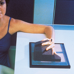
Digits (Second Through Fifth)
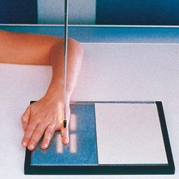
Position of part: When radiographing individual digits (except the first), take the following steps:
• Place the extended digit with the palmar surface down on the unmasked portion of the IR.
• Separate the digits slightly, and center the digit under examination to the midline portion of the IR.
• Center the PIP joint to the IR (Figs. 4-13 to 4-15).

The digit for all projections must be centered to the plate or plate section with four collimator margins or with no margins at all. Two images can be projected on one plate; however, there should be four collimator margins for each projection. A lead blocker must cover the unexposed side when two images are made on one IR.
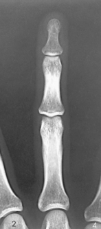
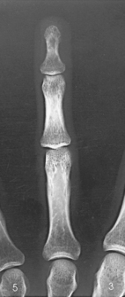
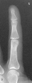
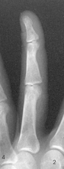
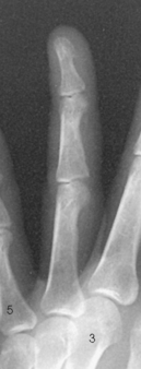
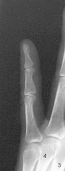
Structures shown: A PA projection of the appropriate digit is visualized (Figs. 4-16 through 4-19).
The following should be clearly shown:
 Evidence of proper collimation
Concavity of the phalangeal shafts and an equal amount of soft tissue on both sides of the phalanges
Fingernail, if visualized and normal, centered over the distal phalanx
Entire digit from fingertip to distal portion of the adjoining metacarpal
No soft tissue overlap from adjacent digits
NOTE: Digits that cannot be extended can be examined in small sections. When joint injury is suspected, an AP projection is recommended instead of a PA projection.
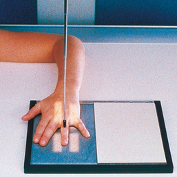
 LATERAL PROJECTION
• Because lateral digit positions are difficult to hold, tell the patient how the digit is adjusted on the IR and demonstrate with your own finger. Let the patient assume the most comfortable arm position.
• Ask the patient to extend the digit to be examined. Close the rest of the digits into a fist and hold them in complete flexion with the thumb.
• Support the elbow on sandbags or provide other suitable support when the elbow must be elevated to bring the digit into position.
• With the digit under examination extended and other digits folded into a fist, have the patient’s hand rest on the lateral, or radial, surface for the second or third digit (Figs. 4-20 and 4-21) or on the medial, or ulnar, surface for the fourth or fifth digit (Figs. 4-22 and 4-23).
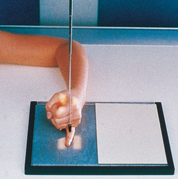
• Before making the final adjustment of the digit position, place the IR so that the midline of its unmasked portion is parallel with the long axis of the digit. Center the IR to the PIP joint.
• Rest the second and fifth digits directly on the IR, but for an accurate image of the bones and joints, elevate the third and fourth digits and place their long axes parallel with the plane of the IR. A radiolucent sponge may be used to support the digits.
• Immobilize the extended digit by placing a strip of adhesive tape, a tongue depressor, or other support against its palmar surface. The patient can hold the support with the opposite hand.
• Adjust the anterior or posterior rotation of the hand to obtain a true lateral position of the digit.
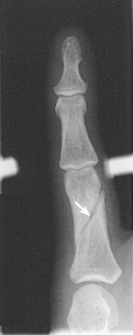
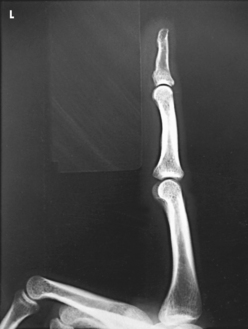
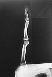
Structures shown: A lateral projection of the affected digit is shown (Figs. 4-24 through 4-27).
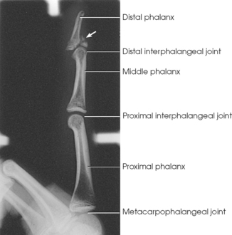
Fig. 4-24 Lateral digit showing chip fracture (arrow) and dislocation involving DIP joint of second digit (arrow).

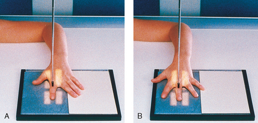
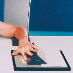
PA OBLIQUE PROJECTION
• Place the patient’s forearm on the table with the hand pronated and the palm resting on the IR.
• Center the IR at the level of the PIP joint.
• Rotate the hand laterally until the digits are separated and supported on a 45degree foam wedge. The wedge supports the digits in a position parallel with the IR plane (Figs. 4-28 through 4-31) so that the IP joint spaces are open.
Structures shown: The resultant image shows a PA oblique projection of the bones and soft tissue of the affected digit (Figs. 4-32 through 4-35).
The following should be clearly shown:
Evidence of proper collimation
Entire digit rotated at a 45-degree angle, including the distal portion of the adjoining metacarpal
No superimposition of the adjacent digits over the proximal phalanx or MCP joint
OPTION: Some radiographers rotate the second digit medially from the prone position (Fig. 4-36). The advantage of medially rotating the digit is that the part is closer to the IR for improved recorded detail and increased visibility of certain fractures.1
1Street JM: Radiographs of phalangeal fractures: importance of the internally rotated oblique projection for diagnosis, AJR Am J Roentgenol 160:575, 1993.
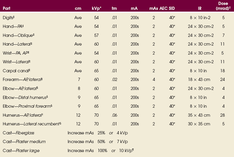
First Digit (Thumb)
AP PROJECTION
• Demonstrate how to avoid motion or rotation with the hand. By adjusting the body position on the chair, the patient can place the hand in the correct position with the least amount of strain on the arm.
• Put the patient’s hand in a position of extreme medial rotation. Have the patient hold the extended digits back with tape or the opposite hand. Rest the thumb on the IR. If the elbow is elevated, place a support under it and have the patient rest the opposite forearm against the table for support (Fig. 4-37).
• Center the long axis of the thumb parallel with the long axis of the IR. Adjust the position of the hand to ensure a true AP projection of the thumb. Place the fifth metacarpal back far enough to avoid superimposition.
• Lewis1 suggested directing the central ray 10 to 15 degrees along the long axis of the thumb toward the wrist to show the first metacarpal free of the soft tissue of the palm.
PA PROJECTION
• If a PA projection of the first CMC joint and first digit is to be performed, place the hand in the lateral position. Rest the elevated and abducted thumb on a radiographic support, or hold it up with a radiolucent stick. Adjust the hand to place the dorsal surface of the digit parallel with the IR. This position magnifies the part (Fig. 4-38).
LATERAL PROJECTION
• Place the hand in its natural arched position with the palmar surface down and fingers flexed or resting on a sponge.
• Place the midline of the IR parallel with the long axis of the digit. Center the IR to the MCP joint.
• Adjust the arching of the hand until a true lateral position of the thumb is obtained (Fig. 4-39).
PA OBLIQUE PROJECTION
• With the thumb abducted, place the palmar surface of the hand in contact with the IR. Ulnar deviate the hand slightly. This relatively normal placement positions the thumb in the oblique position.
• Align the longitudinal axis of the thumb with the long axis of the IR. Center the IR to the MCP joint (Fig. 4-40).
Structures shown: AP, PA, lateral, and PA oblique projections of the thumb are shown (Figs. 4-41 through 4-44).
The following should be clearly shown:
Evidence of proper collimation
 Concavity of the phalangeal and metacarpal shafts
Area from the distal tip of the thumb to the trapezium
Open IP and MCP joint spaces without overlap of bones
Overlap of soft tissue profile of the palm over the mid-shaft of the first metacarpal
First Carpometacarpal Joint
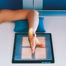
Robert1 first described the radiographic projection of the first CMC joint in 1936. Lewis2 modified the central ray for this projection in 1988, and Long and Rafert3 further modified the central ray in 1995. This projection is commonly performed to show arthritic changes, fractures, displacement of the first CMC joint, and Bennett fracture. The Robert method does not replace the initial AP or PA thumb projection.
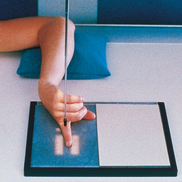
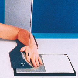
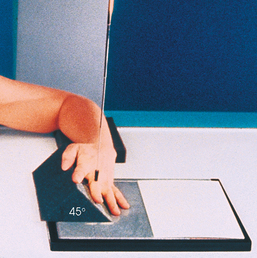
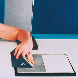
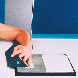
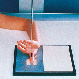
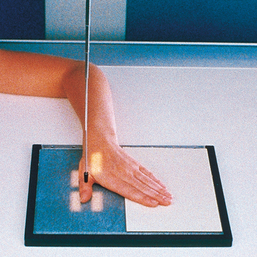
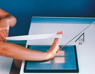
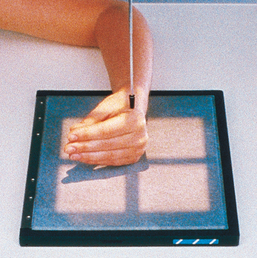
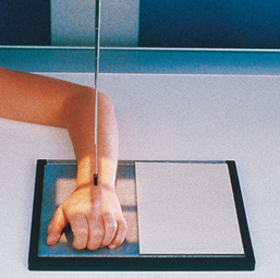
• Seat the patient sideways at the end of the radiographic table. The patient should be positioned low enough to place the shoulder, elbow, and wrist on the same plane. The entire limb must be on the same plane to prevent elevation of the carpal bones and closing of the first CMC joint (Fig. 4-45, A).
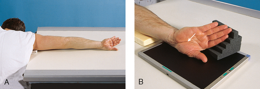
Fig. 4-45 A, Patient in position for AP thumb to show first CMC joint: Robert method. The patient leans forward to place entire arm on same plane and for ease of maximum internal arm rotation. B, Thumb, hand, and wrist in correct position for AP of first CMC joint. Note specific area of wrist where joint is located (arrow).
• Extend the limb straight out on the radiographic table.
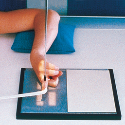
• Rotate the arm internally to place the posterior aspect of the thumb on the IR with the thumbnail down (Fig. 4-45, B).
• Place the thumb in the center of the IR.
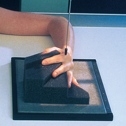
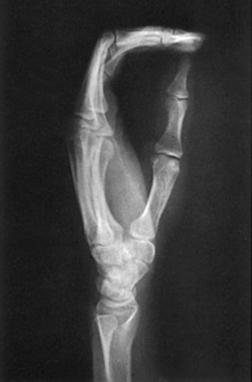
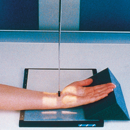
• Hyperextend the hand so that the soft tissue over the ulnar aspect does not obscure the first CMC joint (Fig. 4-46). Ensure that the thumb is not oblique.
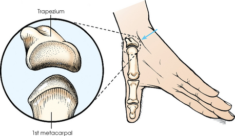
Fig. 4-46 Hyperextended hand and thumb position for AP projection of first CMC joint: Robert method. Soft tissue of palm (arrow) is positioned out of the way so that joint is clearly shown. Inset: First CMC joint is a saddle joint; articular surfaces are shown.
• Long and Rafert1 stated that the patient may hold the fingers back with the other hand.
Central ray (Fig. 4-47): Robert method
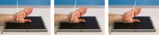
Fig. 4-47 Central ray angulation choices to show first CMC joint. A, Robert method, 0 degrees to CMC joint. B, Long-Rafert modification, 15 degrees proximal to CMC joint. C, Lewis modification, 10 to 15 degrees proximal to MCP joint.
• Angled 10 to 15 degrees proximally along the long axis of the thumb and entering the first MCP joint
NOTE: Angulation of the central ray serves two purposes: (1) It may help project the soft tissue of the hand away from the first CMC joint, and (2) it can help open the joint space when the space is not shown with a perpendicular central ray.
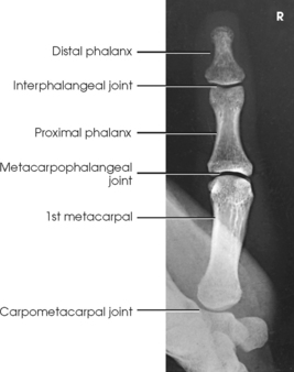
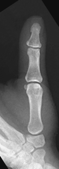
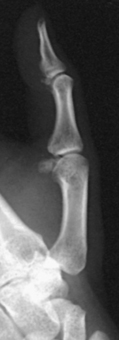
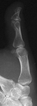
Structures shown: This projection shows the first CMC joint free of superimposition of the soft tissues of the hand (Fig. 4-48).
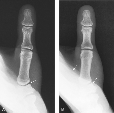
Fig. 4-48 A, Optimal radiograph of AP first CMC joint (arrow): Robert method. B, Example of typical repeat radiograph. Soft tissue of palm (arrows) obscured first CMC joint. Long-Rafert or Lewis modification of central ray would help show the joint on this patient.
First Carpometacarpal Joint
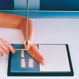
When hyperextension of the wrist is not contraindicated, Burman1 stated that this projection provides a clearer image of the first CMC joint than the standard AP projection.
Image receptor: 8 × 10 inch (18 × 24 cm) lengthwise
SID: The recommended distance is 18 inches; this produces a magnified image that creates a greater field of view of the concavoconvex aspect of this joint.
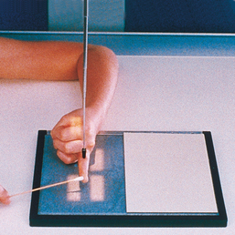
• Place the IR under the wrist, and center the first CMC joint to the center of the IR.
• Hyperextend the hand, and have the patient hold the position with the opposite hand or with a bandage looped around the digits.
• Rotate the hand internally, and abduct the thumb so that it is flat on the IR (Fig. 4-49).
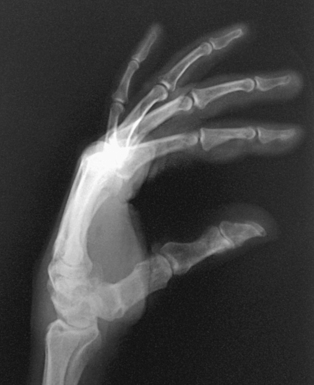
Structures shown: This image shows a magnified concavoconvex outline of the first CMC joint (Fig. 4-50).
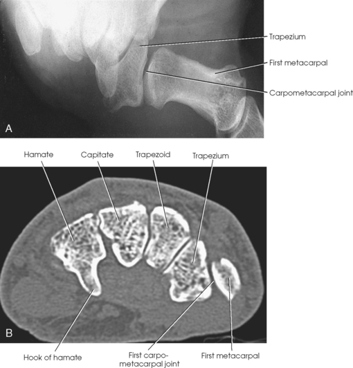
Fig. 4-50 A, AP thumb to demonstrate show the first CMC joint: Burman method. B, Axial CT scan through distal carpals. Note CMC joint is well visualized. (A, Courtesy Michael Burman.)
First Metacarpophalangeal Joint
This projection is useful for the diagnosis of ulnar collateral ligament (UCL) rupture in the MCP joint of the thumb, also known as “skier’s thumb.”1
• Place the patient’s hands on the cassette, resting them on their medial aspects.
• Tightly wrap a rubber band around the distal portion of both thumbs and place a roll of medical tape between the bodies of the first metacarpals.
• Ensure the thumbs remain in the PA plane by keeping the thumbnails parallel to the cassette (Fig. 4-51).
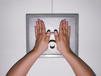
Fig. 4-51 Hands and thumbs in position for PA first MCP joints: Folio method. Note roll of tape between thumbs.
• Before exposure, instruct the patient to pull the thumbs apart and hold.
NOTE: To avoid motion, have the correct technical factors set on the generator and be ready to make the exposure before instructing the patient to pull the thumbs apart.
Structures shown: This projection shows the MCP joints and MCP angles bilaterally (Fig. 4-52).
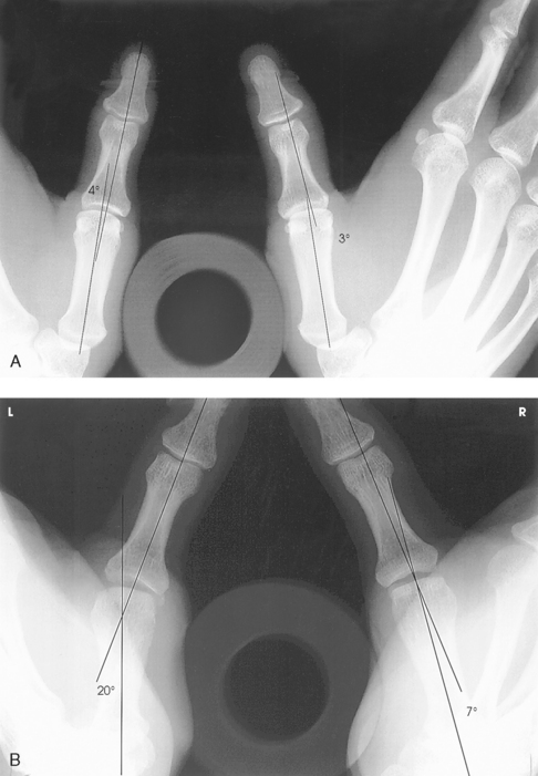
Fig. 4-52 First MCP joint, Folio method. A, Normal thumbs with acceptable MCP joints bilaterally. Roll of tape between metacarpals and rubber band holding distal aspects of thumbs are visible. B, Increased angulation of left MCP joint with 13-degree difference compared with right MCP joint. Partially torn left UCL measures 20 degrees between long axis of first metacarpal and proximal phalanx, whereas uninjured side measures 7 degrees.
RESEARCH: Catherine E. Hearty, MS, RT(R), performed the research and provided this new projection for the atlas.
Hand
Image receptor: 8 × 10 inch (18 × 24 cm) for hand of average size or 10 × 12 inch (24 × 30 cm) crosswise for two images
• Seat the patient at the end of the radiographic table.
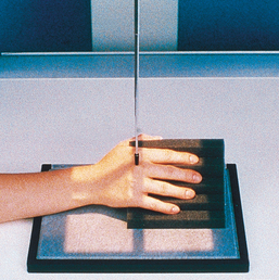
• Adjust the patient’s height so that the forearm is resting on the table (Fig. 4-53, A).
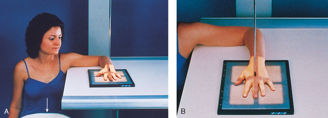
• Rest the patient’s forearm on the table, and place the hand with the palmar surface down on the IR.
• Center the IR to the MCP joints, and adjust the long axis of the IR parallel with the long axis of the hand and forearm.
• Spread the fingers slightly (Fig. 4-53, B).
• Ask the patient to relax the hand to avoid motion. Prevent involuntary movement with the use of adhesive tape or positioning sponges. A sandbag may be placed over the distal forearm.
The hand must be centered to the plate or plate section with four collimator margins or with no margins at all. Two images can be projected on one plate; however, because the hand takes up most of the plate half, collimate to the margins of the plate. A lead blocker must cover the opposite side when two images are made on one IR.
Structures shown: PA projections of the carpals, metacarpals, phalanges (except the thumb), interarticulations of the hand, and distal radius and ulna are shown in Fig. 4-54. This image also shows a PA oblique projection of the first digit.
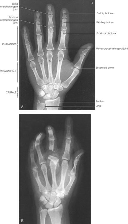
Fig. 4-54 A, PA hand. B, PA hand showing closed, displaced, transverse fracture of third proximal phalanx with dislocation of MCP joint. Overall hand was placed in correct position despite trauma. This gives physician accurate information about displacement of bone.
The following should be clearly shown:
Evidence of proper collimation
Equal concavity of the metacarpal and phalangeal shafts on both sides
Equal amount of soft tissue on both sides of the phalanges
Fingernails, if visualized, in the center of each distal phalanx
Open MCP and IP joints, indicating that the hand is placed flat on the IR
Slightly separate digits with no soft tissue overlap
NOTE: When the MCP joints are under examination and the patient cannot extend the hand enough to place its palmar surface in contact with the IR, the position of the hand can be reversed for an AP projection. This position is also used for the metacarpals when the hand cannot be extended because of an injury, a pathologic condition, or the use of dressings.
SPECIAL TECHNIQUES: Clements and Nakayama1 described a special exposure technique for imaging early rheumatoid arthritis. Lewis2 described a positioning variation to place the second through fifth metacarpals parallel to the IR, resulting in a true PA projection.
1Clements RW, Nakayama HK: Technique for detecting early rheumatoid arthritis, Radiol Technol 62:443, 1991.
2Lewis S: New angles on the radiographic examination of the hand—I, Radiogr Today 54:44-45, 1988.
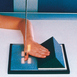
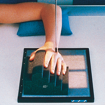
PA OBLIQUE PROJECTION
Image receptor: 8 × 10 inch (18 × 24 cm) lengthwise or 10 × 12 inch (24 × 30 cm) crosswise for two images
• Rest the patient’s forearm on the table with the hand pronated and the palm resting on the IR.
• Adjust the obliquity of the hand so that the MCP joints form an angle of approximately 45 degrees with the IR plane.
• Use a 45-degree foam wedge to support the fingers in the extended position to show the IP joints (Figs. 4-55 and 4-56).
• When examining the metacarpals, obtain a PA oblique projection of the hand by rotating the patient’s hand laterally (externally) from the pronated position until the fingertips touch the IR (Fig. 4-57).
• If it is impossible to obtain the correct position with all fingertips resting on the IR, elevate the index finger and thumb on a suitable radiolucent material (see Fig. 4-56). Elevation opens the joint spaces and reduces the degree of foreshortening of the phalanges.
• For either approach, center the IR to the MCP joints and adjust the midline to be parallel with the long axis of the hand and forearm.
Structures shown: The resulting image shows a PA oblique projection of the bones and soft tissues of the hand (Fig. 4-58). This supplemental position is used for investigating fractures and pathologic conditions.
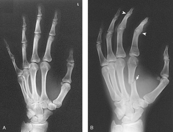
Fig. 4-58 A, PA oblique hand with digits on sponge to show open joints. B, PA oblique hand without support sponge, showing fracture (arrow). IP joints (arrowheads) are not entirely open, and phalanges are foreshortened.
The following should be clearly shown:
Evidence of proper collimation
Minimal overlap of the third-fourth and fourth-fifth metacarpal shafts
Slight overlap of the metacarpal bases and heads
Separation of the second and third metacarpals
Digits separated slightly with no overlap of their soft tissues
NOTE: Lane et al.1 recommended the inclusion of a reverse oblique projection to show severe metacarpal deformities or fractures better. This projection is accomplished by having the patient rotate the hand 45 degrees medially (internally) from the palm-down position.
Kallen2 recommended using a tangential oblique projection to show metacarpal head fractures. From the PA hand position, the MCP joints are flexed 75 to 80 degrees with the dorsum of the digits resting on the IR. The hand is rotated 40 to 45 degrees toward the ulnar surface. Then the hand is rotated 40 to 45 degrees forward until the affected MCP joint is projected beyond its proximal phalanx. The perpendicular central ray is directed tangentially to enter the MCP joint of interest. Variations of rotation are described to show the second metacarpal head free of superimposition.
1Lane CS, Kennedy JF, Kuschner SH: The reverse oblique x-ray film: metacarpal fractures revealed, J Hand Surg Am 17:504, 1992.
2Kallen MJ: Kallen projection reveals metacarpal head fractures, Radiol Technol 65:229, 1994.
LATERAL PROJECTION
Mediolateral or lateromedial Extension and fan lateral
Image receptor: 8 × 10 inch (18 × 24 cm) lengthwise for hand of average size or 10 × 12 inch (24 × 30 cm) crosswise for two images
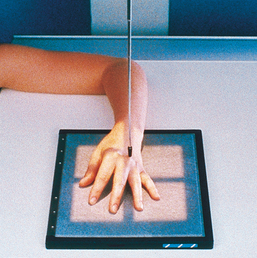
• Seat the patient at the end of the radiographic table with the forearm in contact with the table and the hand in the lateral position with the ulnar aspect down (Fig. 4-59).
• Alternatively, place the radial side of the wrist against the IR (Fig. 4-60). This position is more difficult for the patient to assume.
• Extend the patient’s digits and adjust the first digit at a right angle to the palm.
• Place the palmar surface perpendicular to the IR.
• Center the IR to the MCP joints, and adjust the midline to be parallel with the long axis of the hand and forearm. If the hand is resting on the ulnar surface, immobilization of the thumb may be necessary.
• The two extended digit positions result in superimposition of the phalanges. A modification of the lateral hand is the fan lateral position, which eliminates superimposition of all but the proximal phalanges. For the fan lateral position, place the digits on a sponge wedge. Abduct the thumb and place it on the radiolucent sponge for support (Fig. 4-61).
Structures shown: This image, which shows a lateral projection of the hand in extension (Fig. 4-62), is the customary position for localizing foreign bodies and metacarpal fracture displacement. The exposure technique depends on the foreign body.
The fan lateral superimposes the metacarpals but shows almost all of the individual phalanges. The most proximal portions of the proximal phalanges remain superimposed (Fig. 4-63).
The following should be clearly shown:
Evidence of proper collimation
Hand is in a true lateral position if the following are seen:
Thumb free of motion and superimposition
Each bone outlined through the superimposed shadows of the other metacarpals
NOTE: To show fractures of the fifth metacarpal better, Lewis1 recommended rotating the hand 5 degrees posteriorly from the true lateral position. This positioning removes the superimposition of the second through fourth metacarpals. The thumb is extended as much as possible, and the hand is allowed to become hollow by relaxation. The central ray is angled so that it passes parallel to the extended thumb and enters the midshaft of the fifth metacarpal.
1Lewis S: New angles on the radiographic examination of the hand—II, Radiogr Today 54:29, 1988.
LATERAL PROJECTION
This projection is useful when a hand injury prevents the patient from extending the fingers.
• Center the IR to the MCP joints, and adjust it so that its midline is parallel with the long axis of the hand and forearm.
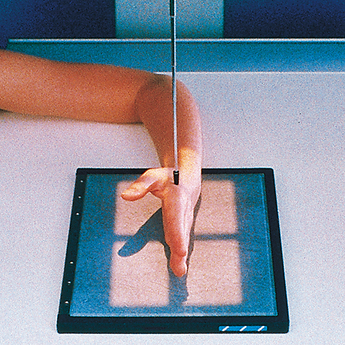
• With the patient relaxing the digits to maintain the natural arch of the hand, arrange the digits so that they are perfectly superimposed (Fig. 4-64).
• Have the patient hold the thumb parallel with the IR, or, if necessary, immobilize the thumb with tape or a sponge.
Structures shown: This projection produces a lateral image of the bony structures and soft tissues of the hand in their normally flexed position (Fig. 4-65). It also shows anterior or posterior displacement in fractures of the metacarpals.
The following should be clearly shown:
Superimposed phalanges and metacarpals
Superimposed distal radius and ulna
No motion or superimposition of the first digit
Radiographic density similar to frontal and oblique hand images, which requires increased exposure factors to compensate for greater hand thickness
Clear outline of each bone through the superimposed shadows of the other metacarpals
AP OBLIQUE PROJECTION
Medial rotation
The Norgaard method,123 sometimes referred to as the ball-catcher’s position, assists in detecting early radiologic changes in the dorsoradial aspects of the second through fifth proximal phalangeal bases, needed to diagnose rheumatoid arthritis. Norgaard reported that it is often possible to make an early diagnosis of rheumatoid arthritis by using this position before laboratory tests are positive.3 He also stated that extremely fine-grain intensifying screens should be used to show high resolution. Low kVp (60 to 65 kVp) is recommended to obtain necessary contrast.
In a more recent article, Stapczynski3 recommended this projection to show fractures of the base of the fifth metacarpal.
• Have the patient place the palms of both hands together. Center the MCP joints on the medial aspect of both hands to the IR. Both hands should be in the lateral position.
• Place two 45-degree radiolucent sponges against the posterior aspect of each hand.
• Rotate the patient’s hands to a halfsupinated position until the dorsal surface of each hand rests against each 45-degree sponge support (Fig. 4-66).
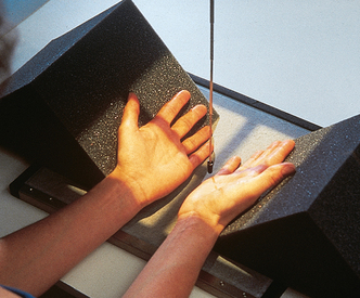
• Extend the patient’s fingers, and abduct the thumbs slightly to avoid superimposing them over the second MCP joint.
• The original method of positioning the hands is often modified. The patient is positioned similar to the method described except that the fingers are not extended. Instead the fingers are cupped as though the patient were going to catch a ball (Fig. 4-67). Comparable diagnostic information is provided using either position.
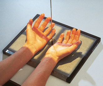
Structures shown: The resulting image shows an AP 45degree oblique projection of both hands (Fig. 4-68). The early radiologic change significant in making the diagnosis of rheumatoid arthritis is a symmetric, very slight, indistinct outline of the bone corresponding to the insertion of the joint capsule dorsoradial on the proximal end of the first phalanx of the four fingers. In addition, associated demineralization of the bone structure is always present in the area directly below the contour defect.
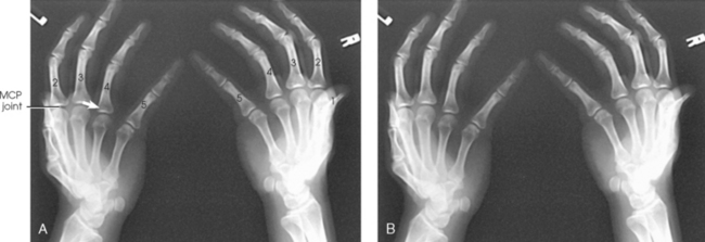
Fig. 4-68 A, AP oblique hands, ball-catcher’s position, showing where indistinct area occurs at dorsoradial aspect of proximal phalangeal base (arrow). B, Ball-catcher’s position.
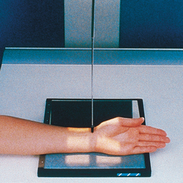
Wrist
• Have the patient rest the forearm on the table, and center the wrist joint to the IR area. The wrist (radiocarpal) joint is at a level just distal to the ulnar styloid.
• When it is difficult to determine the exact location of the radiocarpal joint because of a swollen wrist, ask the patient to flex the wrist slightly, and center the IR to the point of flexion. When the wrist is in a cast or splint, the exact point of centering can be determined by comparison with the opposite side.
• Adjust the hand and forearm to lie parallel with the long axis of the IR.
• Slightly arch the hand at the MCP joints by flexing the digits to place the wrist in close contact with the IR (Fig. 4-69).
• When necessary, place a support under the digits to immobilize them.
The wrist must be centered to the plate or plate section with four collimator margins or with no margins at all. Two images can be projected on one plate; however, there must be four collimator margins for each projection. A lead blocker must cover the opposite side when two images are made on one IR.
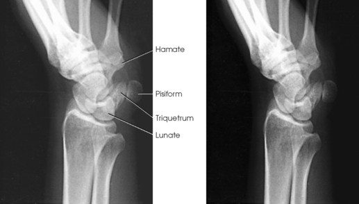
Structures shown: A PA projection of the carpals, distal radius and ulna, and proximal metacarpals is shown (Fig. 4-70). The projection gives a slightly oblique rotation to the ulna. When the ulna is under examination, an AP projection should be taken.
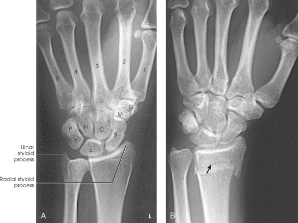
Fig. 4-70 A, PA wrist. C, capitate; G, trapezium; H, hamate; L, lunate; M, trapezoid; P, pisiform; S, scaphoid; T, triquetrum. B, PA wrist showing Smith fracture of distal radius (arrow).
The following should be clearly shown:
Evidence of proper collimation
Distal radius and ulna, carpals, and proximal half of metacarpals
No rotation in carpals, metacarpals, or radius
Soft tissue and bony trabeculation
No excessive flexion to overlap and obscure metacarpals with digits
NOTE: To show the scaphoid and capitate better, Daffner et al.* recommended angling the central ray when the patient is positioned for a PA radiograph. A central ray angle of 30 degrees toward the elbow elongates the scaphoid and capitate, whereas an angle of 30 degrees toward the fingertips elongates only the capitate.
*Daffner RH, Emmerling EW, Buterbaugh GA: Proximal and distal oblique radiography of the wrist: value in occult injuries, J Hand Surg Am 17:499, 1992.
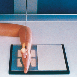
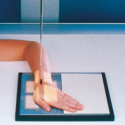
AP PROJECTION
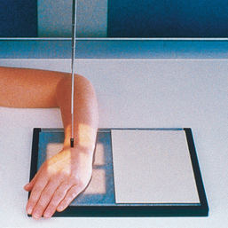
• Have the patient rest the forearm on the table, with the arm and hand supinated.
• Place the IR under the wrist, and center it to the carpals.
• Elevate the digits on a suitable support to place the wrist in close contact with the IR.
• Have the patient lean laterally to prevent rotation of the wrist (Fig. 4-71).
Structures shown: The carpal interspaces are better shown in the AP image than the PA image. Because of the oblique direction of the interspaces, they are more closely parallel with the divergence of the x-ray beam (Fig. 4-72).
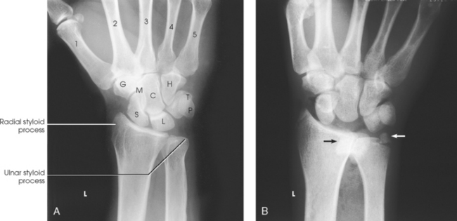
Fig. 4-72 A, AP wrist. C, capitate; G, trapezium; H, hamate; L, lunate; M, trapezoid; P, pisiform; S, scaphoid; T, triquetrum. B, AP wrist showing complete dislocation of lunate (black arrow) and fracture of ulnar styloid process (white arrow).
LATERAL PROJECTION
• Have the patient flex the elbow 90 degrees to rotate the ulna to the lateral position.
• Center the IR to the wrist (radiocarpal) joint, and adjust the forearm and hand so that the wrist is in a true lateral position (Fig. 4-73).
Structures shown: This image shows a lateral projection of the proximal metacarpals, carpals, and distal radius and ulna (Fig. 4-74). An image obtained with the radial surface against the IR (Fig. 4-75) is shown for comparison. This position can also be used to show anterior or posterior displacement in fractures.
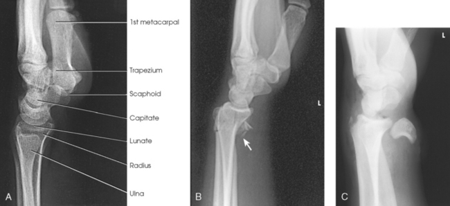
Fig. 4-74 A, Lateral wrist with ulnar surface to IR. B, Lateral with Smith fracture (arrow). This is the same patient as in Fig. 4-70, B. C, Lateral wrist showing obvious complete anterior dislocation of lunate bone. This is the same patient as in Fig. 4-72, A. A lighter exposure was used to show soft tissue.
The following should be clearly shown:
Evidence of proper collimation
Distal radius and ulna, carpals, and proximal half of metacarpals
Superimposed distal radius and ulna
Radiographic density similar to PA or AP and oblique radiographs, which requires increased exposure factors to compensate for greater part thickness
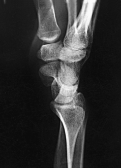
NOTE: Burman et al.1 suggested that the lateral position of the scaphoid should be obtained with the wrist in palmar flexion because this action rotates the bone anteriorly into a dorsovolar position (Fig. 4-76). This position is valuable, however, only when sufficient flexion is permitted.
Fiolle23 was the first to describe a small bony growth occurring on the dorsal surface of the third CMC joint. He termed the condition carpe bossu (carpal boss) and found that it is shown best in a lateral position with the wrist in palmar flexion (see Fig. 4-76).
1Burman MS et al: Fractures of the radial and ulnar axes, AJR Am J Roentgenol 51:455, 1944.
2Fiolle J: Le “carpe bossu,” Bull Soc Chir Paris 57:1687, 1931.
3Fiolle J et al: Nouvelle observation de “carpe bossu,” Bull Soc Chir Paris 58:187, 1932.
PA OBLIQUE PROJECTION
• Rest the palmar surface of the wrist on the IR.
• Adjust the IR so that its center point is under the scaphoid when the wrist is rotated from the pronated position.
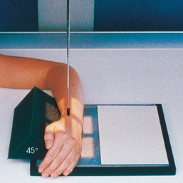
• From the pronated position, rotate the wrist laterally (externally) until it forms an angle of approximately 45 degrees with the plane of the IR. For exact positioning and to ensure duplication in follow-up examinations, place a 45degree foam wedge under the elevated side of the wrist.
• Extend the wrist slightly, and if the digits do not touch the table, support them in place (Fig. 4-77).
• When the scaphoid is under examination, adjust the wrist in ulnar deviation. Place a sandbag across the forearm.
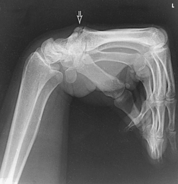
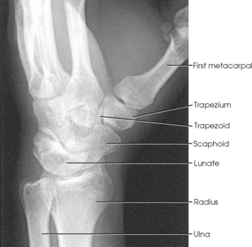
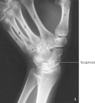
Structures shown: This projection shows the carpals on the lateral side of the wrist, particularly the trapezium and the scaphoid. The scaphoid is superimposed on itself in the direct PA projection (Figs. 4-78 and 4-79).
The following should be clearly shown:
Evidence of proper collimation
A well-shown trapezium and the distal half of the scaphoid
Distal radius and ulna, carpals, and proximal half of metacarpals
Open trapeziotrapezoid and scaphotrapezial joint space
Usually, adequate amount of obliquity in the following circumstances
AP OBLIQUE PROJECTION1
• Place the IR under the wrist and center it at the dorsal surface of the wrist.
• Rotate the wrist medially (internally) until it forms a semisupinated position of approximately 45 degrees to the IR (Fig. 4-80).
Structures shown: This position separates the pisiform from the adjacent carpal bones. It also provides a more distinct radiograph of the triquetrum and hamate (compare Figs. 4-81 and 4-82).
PA PROJECTION
Ulnar deviation1
• Position the wrist on the IR for a PA projection.
• Without moving the forearm, turn the hand outward until the wrist is in extreme ulnar deviation (Fig. 4-83).
Structures shown: This position corrects foreshortening of the scaphoid, which occurs with a perpendicular central ray. It also opens the spaces between the adjacent carpals (Fig. 4-84).
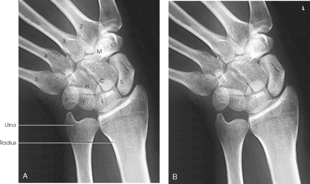
Fig. 4-84 A, PA wrist in ulnar deviation. C, capitate; G, trapezium; H, hamate; L, lunate; M, trapezoid; P, pisiform; S, scaphoid; T, triquetrum. B, Wrist in ulnar deviation.
PA PROJECTION
Radial deviation1
• Position the wrist on the IR for a PA projection.
• Without moving the forearm, turn the hand medially until the wrist is in extreme radial deviation (Fig. 4-85).
Structures shown: Radial deviation opens the interspaces between the carpals on the medial side of the wrist (Fig. 4-86).
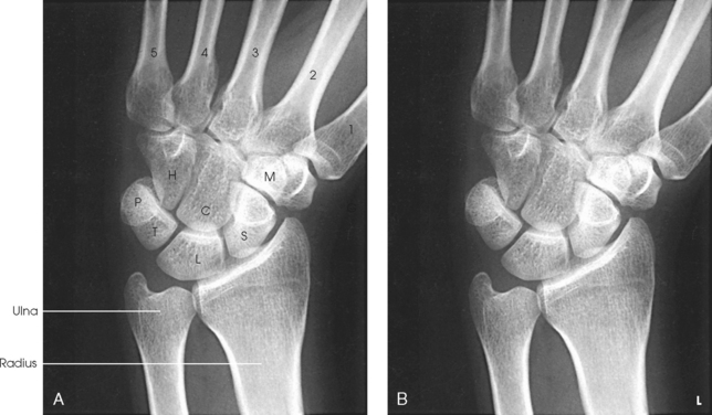
Fig. 4-86 A, PA wrist in radial deviation. C, capitate; G, trapezium; H, hamate; L, lunate; M, trapezoid; P, pisiform; S, scaphoid; T, triquetrum. B, Wrist in radial deviation.