SHOULDER GIRDLE
SUMMARY OF PROJECTIONS
Shoulder Girdle
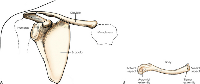
The shoulder girdle is formed by two bones—the clavicle and scapula. The function of these bones is to connect the upper limb to the trunk. Although the alignment of these two bones is considered a girdle, it is incomplete in front and in back. The girdle is completed in front by the sternum, which articulates with the medial end of the clavicle. The scapulae are widely separated in the back. The proximal portion of the humerus is part of the upper limb and not the shoulder girdle proper; however, because the proximal humerus is included in the shoulder joint, its anatomy is considered with that of the shoulder girdle (Figs. 5-1 and 5-2).
Clavicle
The clavicle, classified as a long bone, has a body and two articular extremities (see Fig. 5-1). The clavicle lies in a horizontal oblique plane just above the first rib and forms the anterior part of the shoulder girdle. The lateral aspect is termed the acromial extremity, and it articulates with the acromion process of the scapula. The medial aspect, termed the sternal extremity, articulates with the manubrium of the sternum and the first costal cartilage. The clavicle, which serves as a fulcrum for the movements of the arm, is doubly curved for strength. The curvature is more acute in males than in females.
Scapula
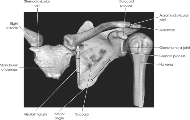
The scapula, classified as a flat bone, forms the posterior part of the shoulder girdle (Figs. 5-3 and 5-4). Triangular in shape, the scapula has two surfaces, three borders, and three angles. Lying on the superoposterior thorax between the second and seventh ribs, the medial border of the scapula runs parallel with the vertebral column. The body of the bone is arched from top to bottom for greater strength, and its surfaces serve as the attachment sites of numerous muscles. The flat aspect of the bone lies at about a 45- to 60-degree angle in relation to the anatomic position (see Fig. 5-2).
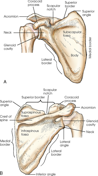
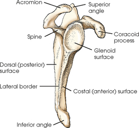
The costal (anterior) surface of the scapula is slightly concave and contains the subscapular fossa. It is filled almost entirely by the attachment of the subscapularis muscle. The anterior serratus muscle attaches to the medial border of the costal surface from the superior angle to the inferior angle.
The dorsal (posterior) surface is divided into two portions by a prominent spinous process. The crest of spine arises at the superior third of the medial border from a smooth, triangular area and runs obliquely superior to end in a flattened, ovoid projection called the acromion. The area above the spine is called the supraspinous fossa and gives origin to the supraspinatus muscle. The infraspinatus muscle arises from the portion below the spine, which is called the infraspinous fossa. The teres minor muscle arises from the superior two thirds of the lateral border of the dorsal surface, and the teres major arises from the distal third and the inferior angle. The dorsal surface of the medial border affords attachment of the levator muscles of the scapulae, greater rhomboid muscle, and lesser rhomboid muscle.
The superior border extends from the superior angle to the coracoid process and at its lateral end has a deep depression, the scapular notch. The medial border extends from the superior to the inferior angles. The lateral border extends from the glenoid cavity to the inferior angle.
The superior angle is formed by the junction of the superior and medial borders. The inferior angle is formed by the junction of the medial (vertebral) and lateral borders and lies over the seventh rib. The lateral angle, the thickest part of the body of the scapula, ends in a shallow, oval depression called the glenoid cavity. The constricted region around the glenoid cavity is called the neck of the scapula. The coracoid process arises from a thick base that extends from the scapular notch to the superior portion of the neck of the scapula. This process projects first anteriorly and medially and then curves on itself to project laterally. The coracoid process can be palpated just distal and slightly medial to the acromioclavicular articulation.
Humerus
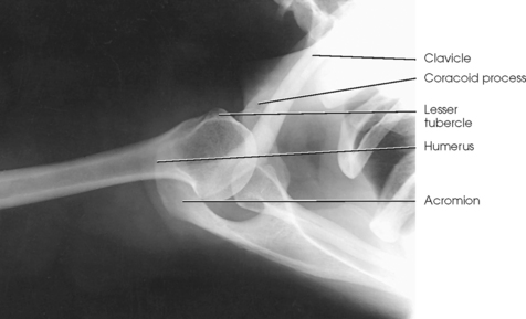
The proximal end of the humerus consists of a head, an anatomic neck, two prominent processes called the greater and lesser tubercles, and the surgical neck (Fig. 5-5). The head is large, smooth, and rounded, and it lies in an oblique plane on the superomedial side of the humerus. Just below the head, lying in the same oblique plane, is the narrow, constricted anatomic neck. The constriction of the body just below the tubercles is called the surgical neck, which is the site of many fractures.
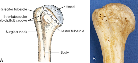
Fig. 5-5 A, Anterior aspect of right proximal humerus. B, Photograph of anterior aspect of proximal humerus.
The lesser tubercle is situated on the anterior surface of the bone, immediately below the anatomic neck (Figs. 5-6 and 5-7; see Fig. 5-5). The tendon of the subscapular muscle inserts at the lesser tubercle. The greater tubercle is located on the lateral surface of the bone, just below the anatomic neck, and is separated from the lesser tubercle by a deep depression called the intertubercular (bicipital) groove. The superior surface of the greater tubercle slopes posteriorly at an angle of approximately 25 degrees and has three flattened impressions for muscle insertions. The anterior impression is the highest of the three and affords attachment to the tendon of the supraspinatus muscle. The middle impression is the point of insertion of the infraspinatus muscle. The tendon of the upper fibers of the teres minor muscle inserts at the posterior impression (the lower fibers insert into the body of the bone immediately below this point).
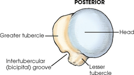
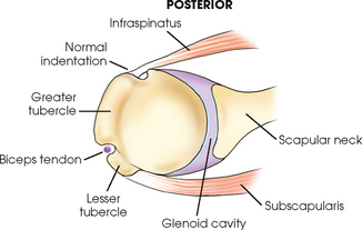
Fig. 5-7 Superior aspect of humerus. Horizontal section through scapulohumeral joint showing normal anatomic relationships.
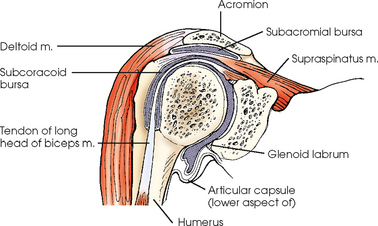
Bursae are small, synovial fluid–filled sacs that relieve pressure and reduce friction in tissue. They are often found between the bones and the skin, and they allow the skin to move easily when the joint is moved. Bursae are found also between bones and ligaments, muscles, or tendons. One of the largest bursae of the shoulder is the subacromial bursa (Fig. 5-8). It is located under the acromion process and lies between the deltoid muscle and the shoulder joint capsule. The subacromial bursa does not normally communicate with the joint. Other bursae of the shoulder are found superior to the acromion, between the coracoid process and the joint capsule, and between the capsule and the tendon of the subscapular muscle. Bursae become important radiographically when injury or age causes the deposition of calcium.
Shoulder Girdle Articulations
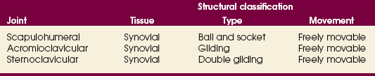
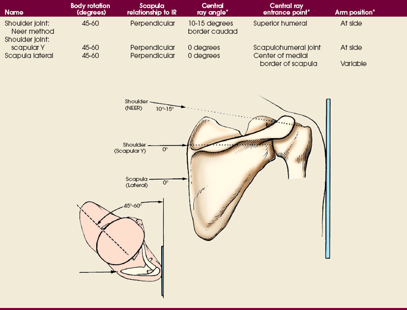
The three joints of the shoulder girdle are summarized in Table 5-1, and a detailed description follows.
SCAPULOHUMERAL ARTICULATION
The scapulohumeral articulation between the glenoid cavity and the head of the humerus forms a synovial ball-and-socket joint, allowing movement in all directions (Figs. 5-9 and 5-10). This joint is often referred to as the glenohumeral joint. Although many muscles connect with, support, and enter into the function of the shoulder joint, radiographers are chiefly concerned with the insertion points of the short rotator cuff muscles (Fig. 5-11). The insertion points of these muscles—the subscapular, supraspinatus, infraspinatus, and teres minor—have already been described.
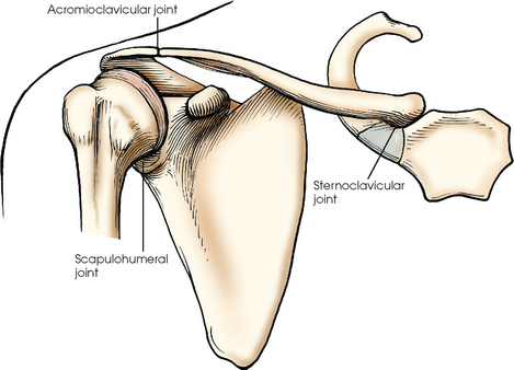
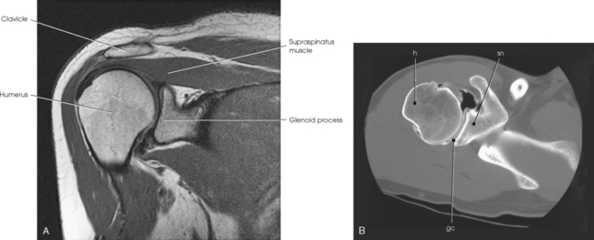
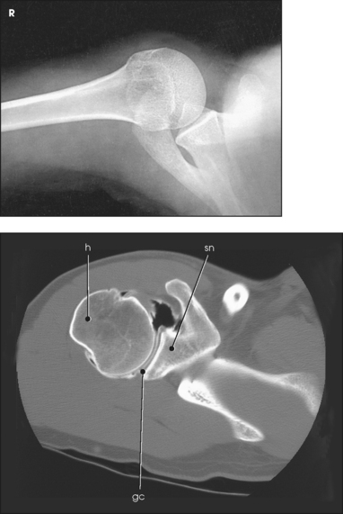
Fig. 5-10 A, Coronal MRI of shoulder. Note articular cartilage around humeral head and muscles closely surrounding bone. B, Axial CT of shoulder, mid-joint. Note position of bones relative to each other and articular cartilage in glenoid cavity. gc, glenoid cavity; h, humerus; sn, scapular neck. (From Kelley LL, Petersen CM: Sectional anatomy for imaging professionals, ed 2, St Louis, 2007, Mosby.)
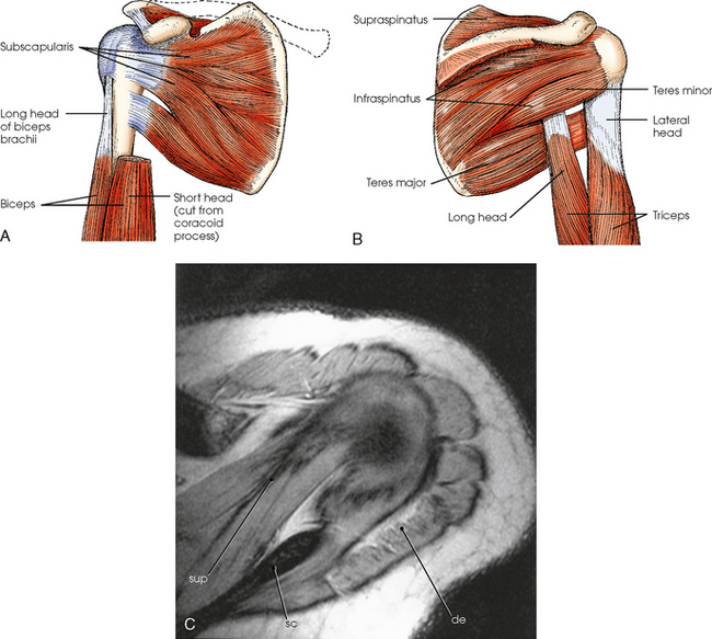
Fig. 5-11 A, Muscles on costal (anterior) surface of scapula and proximal humerus. B, Muscles on dorsal (posterior) surface of scapula and proximal humerus. C, Axial MRI of shoulder (view from top) showing muscles of shoulder. Supraspinatus (sup) and deltoid (de) muscles are shown. Note scapular spine (sc) for reference. (From Kelley LL, Petersen CM: Sectional anatomy for imaging professionals, ed 2, St Louis, 2007, Mosby.)
An articular capsule completely encloses the shoulder joint. The tendon of the long head of the biceps brachii muscle, which arises from the superior margin of the glenoid cavity, passes through the capsule of the shoulder joint, goes between its fibrous and synovial layers, arches over the head of the humerus, and descends through the intertubercular (bicipital) groove. The short head of the biceps arises from the coracoid process and, with the long head of the muscle, inserts in the radial tuberosity. Because it crosses with the shoulder and elbow joints, the biceps help synchronize their action.
The interaction of movement among the wrist, elbow, and shoulder joints makes the position of the hand important in radiography of the upper limb. Any rotation of the hand also rotates the joints. The best approach to the study of the mechanics of joint and muscle action is to perform all movements ascribed to each joint and carefully note the reaction in remote parts.
ACROMIOCLAVICULAR ARTICULATION
The acromioclavicular (AC) articulation between the acromion process of the scapula and the acromial extremity of the clavicle forms a synovial gliding joint (see Fig. 5-12). It permits gliding and rotary (elevation, depression, protraction, and retraction) movement. Because the end of the clavicle rides higher than the adjacent surface of the acromion, the slope of the surfaces tends to favor displacement of the acromion downward and under the clavicle.
STERNOCLAVICULAR ARTICULATION
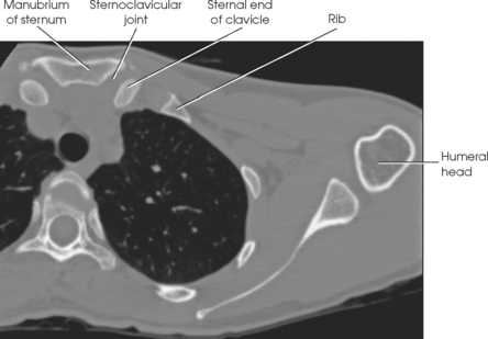
The sternoclavicular (SC) articulation is formed by the sternal extremity of the clavicle with two bones: the manubrium and the first rib cartilage (see Fig. 5-12). The union of the clavicle with the manubrium of the sternum is the only bony union between the upper limb and trunk. This articulation is a synovial double-gliding joint. The joint is adapted by a fibrocartilaginous disk, however, to provide movements similar to a ball-and-socket joint: circumduction, elevation, depression, and forward and backward movements. The clavicle carries the scapula with it through any movement.
SUMMARY OF PATHOLOGY
| Condition | Definition |
| Bursitis | Inflammation of the bursa |
| Dislocation | Displacement of a bone from the joint space |
| Fracture | Disruption in the continuity of bone |
| Hills-Sachs defect | Impacted fracture of posterolateral aspect of the humeral head with dislocation |
| Metastases | Transfer of a cancerous lesion from one area to another |
| Osteoarthritis or degenerative joint disease | Form of arthritis marked by progressive cartilage deterioration in synovial joints and vertebrae |
| Osteopetrosis | Increased density of atypically soft bone |
| Osteoporosis | Loss of bone density |
| Rheumatoid arthritis | Chronic, systemic, inflammatory collagen disease |
| Tendinitis | Inflammation of the tendon and tendon-muscle attachment |
| Tumor | New tissue growth where cell proliferation is uncontrolled |
| Chondrosarcoma | Malignant tumor arising from cartilage cells |
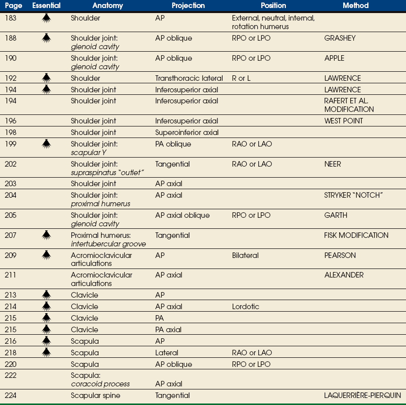
EXPOSURE TECHNIQUE CHART ESSENTIAL PROJECTIONS
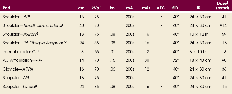
*kVp values are for a three-phase, 12-pulse generator or high frequency.
†Relative doses for comparison use. All doses are skin entrance for average adult at cm indicated.
‡Bucky, 16:1 grid. Screen-film speed 300.
§Tabletop, 8:1 grid. Screen-film speed 300.
¶Tabletop, standard IR. Screen-film speed 300 or equivalent CR.
Radiation Protection
Protection of the patient from unnecessary radiation is a professional responsibility of the radiographer (see Chapters 1 and 2 for specific guidelines). In this chapter, the Shield gonads statement at the end of the Position of part section indicates that the patient is to be protected from unnecessary radiation by using proper collimation and placing lead shielding between the gonads and the radiation source to restrict the radiation beam.
Shoulder
External, neutral, internal rotation humerus
NOTE: Do not have the patient rotate the arm if fracture or dislocation is suspected.
• Center the shoulder joint to the midline of the grid.
• Adjust the position of the IR so that its center is 1 inch (2.5 cm) inferior to the coracoid process.
• Ask the patient to supinate the hand, unless contraindicated (Table 5-2).
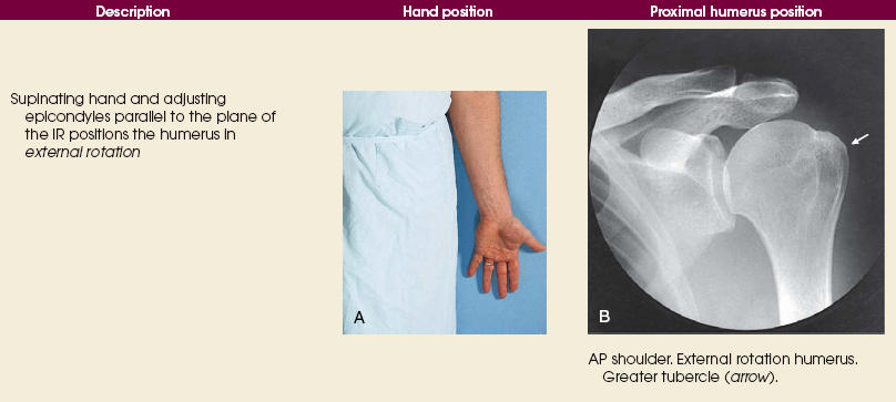
• Abduct the arm slightly, and rotate it so that the epicondyles are parallel with the plane of the IR. Externally rotating the entire arm from the neutral position places the shoulder and entire humerus in the true anatomic position (Fig. 5-13).
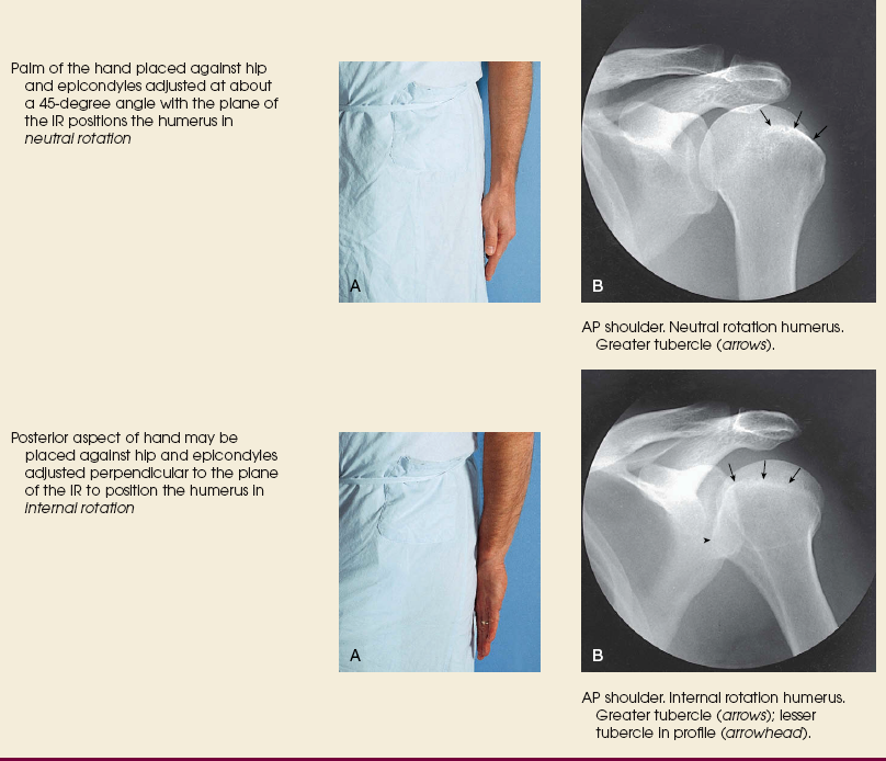
• Ask the patient to rest the palm of the hand against the thigh (see Table 5-2). This position of the arm rolls the humerus slightly internal into a neutral position, placing the epicondyles at an angle of about 45 degrees with the plane of the IR.
• Ask the patient to flex the elbow, rotate the arm internally, and rest the back of the hand on the hip (see Table 5-2).
• Adjust the arm to place the epicondyles perpendicular to the plane of the IR.
 COMPENSATING FILTER
Use of a specially designed compensating filter for the shoulder improves the quality of the image. These filters are particularly useful when digital imaging (CR or DR) systems are used for this projection.
Structures shown: The image shows the bony and soft structures of the shoulder and proximal humerus in the anatomic position (Figs. 5-14 to 5-16). The scapulohumeral joint relationship is seen.
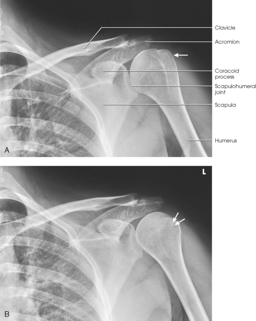
Fig. 5-14 A, AP shoulder, external rotation humerus: greater tubercle in profile (arrow). B, AP shoulder, neutral rotation humerus: greater tubercle (arrow).
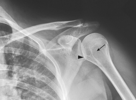
Fig. 5-15 AP shoulder, internal rotation humerus: greater tubercle (arrow); lesser tubercle in profile (arrowhead).
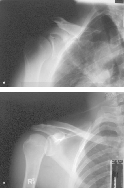
Fig. 5-16 A, AP oblique projection of right shoulder without use of compensating filter. B, AP projection of same patient with compensating filter. Note improvement of visualization of bony and soft tissue areas with filter.
External rotation: The greater tubercle of the humerus and the site of insertion of the supraspinatus tendon are visualized (see Fig. 5-14, A).
Neutral rotation: The posterior part of the supraspinatus insertion, which sometimes profiles small calcific deposits not otherwise visualized (see Fig. 5-14, B), is seen.
Internal rotation: The proximal humerus is seen in a true lateral position. When the arm can be abducted enough to clear the lesser tubercle of the head of the scapula, a profile image of the site of the insertion of the subscapular tendon is seen (see Fig. 5-15).
The following should be clearly shown:
 Evidence of proper collimation
Superior scapula, lateral half of the clavicle, and proximal humerus
Soft tissue around the shoulder, along with bony trabecular detail
Greater tubercle in profile on lateral aspect of the humerus
Scapulohumeral joint visualized with slight overlap of humeral head on glenoid cavity
Outline of lesser tubercle between the humeral head and greater tubercle
Glenoid Cavity
RPO or LPO position
Image receptor: 8 × 10 inch (18 × 24 cm) crosswise
• Center the IR to the scapulohumeral joint. The joint is 2 inches (5 cm) medial and 2 inches (5 cm) inferior to the superolateral border of the shoulder.
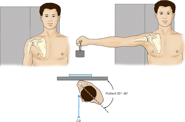
• Rotate the body approximately 35 to 45 degrees toward the affected side (Fig. 5-17).
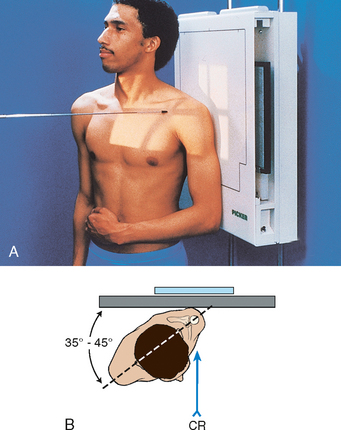
Fig. 5-17 A, Upright AP oblique glenoid cavity: Grashey method. B, Note position of shoulder and patient in relationship to IR.
• Adjust the degree of rotation to place the scapula parallel with the plane of the IR. This is accomplished by orienting the plane through the superior angle of the scapula and acromial tip, parallel to the IR.* The head of the humerus is in contact with the IR.
• If the patient is in the recumbent position, the body may need to be rotated more than 45 degrees (up to 60 degrees) to place the scapula parallel to the IR.
• Support the elevated shoulder and hip on sandbags (Fig. 5-18).
• Abduct the arm slightly in internal rotation, and place palm of the hand on the abdomen.
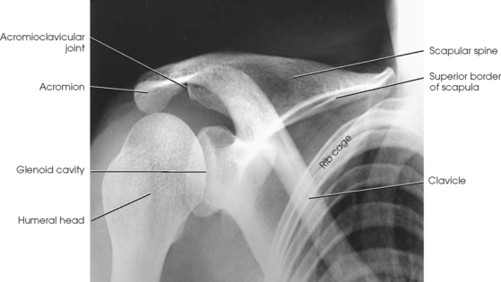
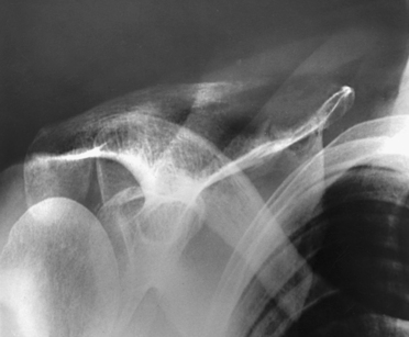
Structures shown: The joint space between the humeral head and the glenoid cavity (scapulohumeral joint) is shown (Figs. 5-19 and 5-20).
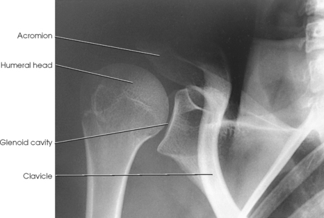
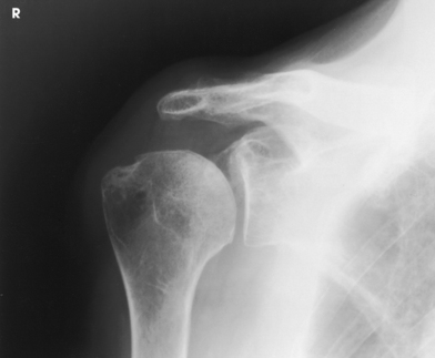
Fig. 5-20 AP oblique glenoid cavity: Grashey method showing moderate deterioration of scapulohumeral joint.
Glenoid Cavity
RPO or LPO position
The Apple method1 is similar to the Grashey method but uses weighted abduction to show a loss of articular cartilage in the scapulohumeral joint.
• Center the IR to the scapulohumeral joint.
• Rotate the body approximately 35 to 45 degrees toward the affected side.
• The posterior surface of affected side is closest to the IR.
• The scapula should be positioned parallel to the plane of the IR (see Grashey method for positioning details).
• The patient should hold a 1-lb weight in the hand on the same side as the affected shoulder in a neutral position.
• While holding the weight, the patient should abduct the arm 90 degrees from the midline of the body (Fig. 5-21).
NOTE: To avoid motion, have the correct technical factors set on the generator and be ready to make the exposure before the patient abducts the arm.
Structures shown: The scapulohumeral joint (Fig. 5-22) is seen.
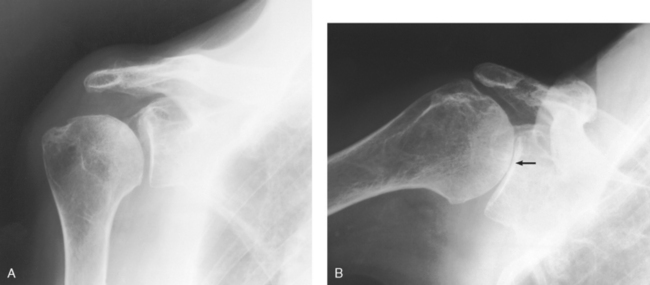
Fig. 5-22 A, AP oblique projection: Grashey method, with shoulder showing normal scapulohumeral joint space. B, AP oblique projection: Apple method, with weighted abduction showing loss of articular cartilage (arrow).
RESEARCH: Catherine E. Hearty, MS, RT(R), performed the research and provided this new projection for this edition of the atlas.
Shoulder
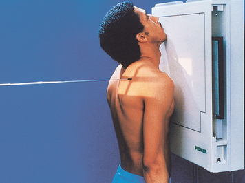
 TRANSTHORACIC LATERAL PROJECTION
R or L position
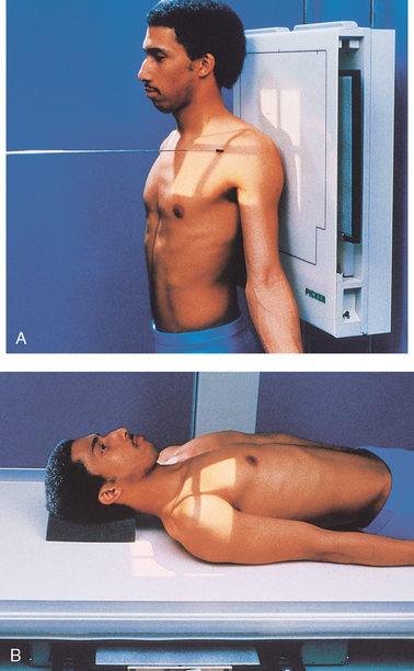
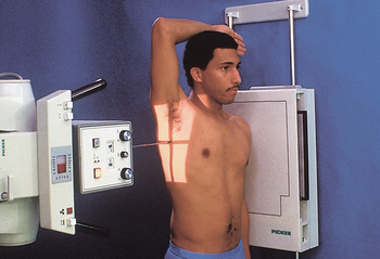
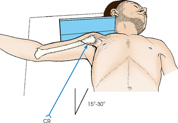
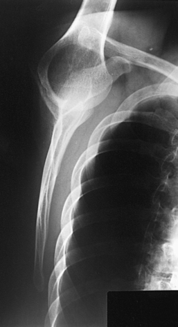
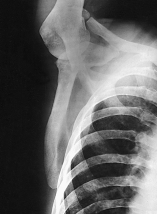
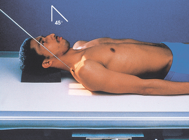
The Lawrence1 method is used when trauma exists, and the arm cannot be rotated or abducted because of an injury. This projection shows the proximal humerus in a 90-degree projection from the AP projection and shows its relationship to the scapula and clavicle.
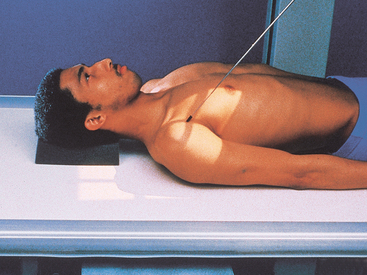
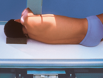
• Although this projection can be carried out with the patient in the upright or supine position, the upright position is much easier on a trauma patient. It also assists accurate adjustment of the shoulder.
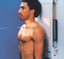
• For upright positioning, seat or stand the patient in the lateral position before a vertical grid device (Fig. 5-23).
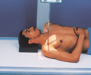
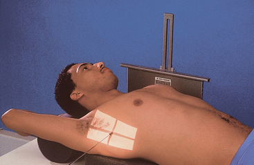
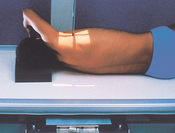
• If an upright position is impossible, place the patient in a recumbent position on the table with radiolucent pads elevating the head and shoulders (Fig. 5-24).
• Have the patient raise the noninjured arm, rest the forearm on the head, and elevate the shoulder as much as possible (see Fig. 5-23). Elevation of the noninjured shoulder drops the injured side, separating the shoulders to prevent superimposition. Ensure that the midcoronal plane is perpendicular to the IR.
• No attempt should be made to rotate or otherwise to move the injured arm.
• Center the IR to the surgical neck area of the affected humerus.
• Respiration: Full inspiration. Having the lungs full of air improves the contrast and decreases the exposure necessary to penetrate the body.
• If the patient can be sufficiently immobilized to prevent voluntary motion, a breathing technique can be used. In this case, instruct the patient to practice slow, deep breathing. A minimum exposure time of 3 seconds (4 to 5 seconds is desirable) gives excellent results when a low milliamperage is used.
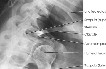
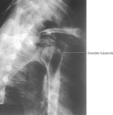
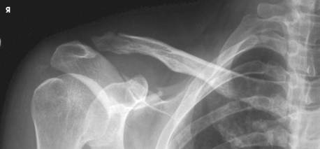
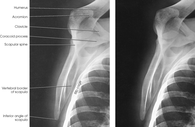
Structures shown: A lateral image of the shoulder and proximal humerus is projected through the thorax (Figs. 5-25 and 5-26).
Shoulder Joint
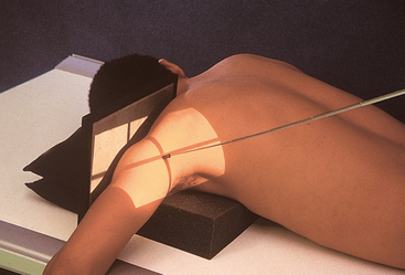
INFEROSUPERIOR AXIAL PROJECTION
RAFERT ET AL.1 MODIFICATION
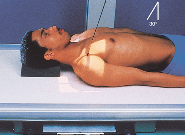
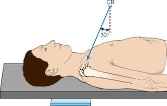
Image receptor: 10 × 12 inch (24 × 30 cm) grid crosswise, placed in the vertical position in contact with the superior surface of the shoulder
• As much as possible, abduct the arm of the affected side at right angles to the long axis of the body.
• Keep the humerus in external rotation, and adjust the forearm and hand in a comfortable position, grasping a vertical support or extended on sandbags or a firm pillow. Support may be necessary under the forearm and hand. Provide the patient with an extension board for the arm.
• Have the patient turn the head away from the side being examined so that the IR can be placed against the neck.
• Place the IR on edge against the shoulder and as close as possible to the neck.
• Support the IR in position with sandbags, or use a vertical IR holder (Fig. 5-27).
• Anterior dislocation of the humeral head can result in a wedge-shaped compression fracture of the articular surface of the humeral head, called the Hill-Sachs defect.1 The fracture is located on the posterolateral humeral head. An exaggerated external rotation of the arm may be required to see the defect.
• With the patient in position exactly as for the Lawrence method, externally rotate the extended arm until the hand forms a 45-degree oblique angle. The thumb is pointing downward (Fig. 5-28).
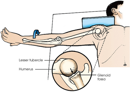
Fig. 5-28 Inferosuperior axial shoulder joint: Rafert modification. Note exaggerated external rotation of arm and thumb pointing downward. If present, a Hill-Sachs defect would show as a wedge-shaped depression on posterior aspect of articulating surface of humeral head (arrow). From Rafert JA et al: Axillary shoulder with exaggerated rotation: the Hill-Sachs defect, Radiol Technol 62:18, 1990.)
• Assist the patient in rotating the arm to avoid overstressing the shoulder joint.
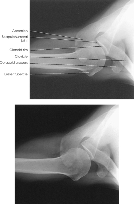
Structures shown: An inferosuperior axial image shows the proximal humerus, the scapulohumeral joint, the lateral portion of the coracoid process, and the AC articulation. The insertion site of the subscapular tendon on the lesser tubercle of the humerus and the point of insertion of the teres minor tendon on the greater tubercle of the humerus are also shown. A Hill-Sachs compression fracture on the posterolateral humeral head may be seen using the Rafert modification (Figs. 5-29 and 5-30).
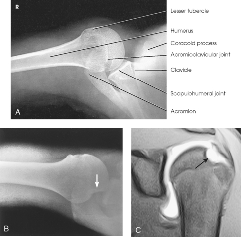
Fig. 5-29 A, Inferosuperior axial shoulder joint: Lawrence method. B, Inferosuperior axial shoulder joint: Rafert modification showing Hill-Sachs defect (arrow). C, Coronal MRI of shoulder joint showing Hill-Sachs defect (arrow) after recurring shoulder dislocation. (A and B, From Rafert JA et al: Axillary shoulder with exaggerated rotation: the Hill-Sachs defect, Radiol Technol 62:18, 1990. C, From Jackson SA, Thomas RM: Cross-sectional imaging made easy, New York, 2004, Churchill Livingstone.)
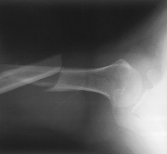
Fig. 5-30 Inferosuperior axial shoulder joint: Lawrence method showing comminuted fracture of humerus. The patient came into emergency department with arm extended out.
INFEROSUPERIOR AXIAL PROJECTION
The West Point1 method is used when chronic instability of the shoulder is suspected and to show bony abnormalities of the anterior inferior glenoid rim. Associated Hill-Sachs defect of the posterior lateral aspect of the humeral head is also shown.
Image receptor: 8 × 10 inch (18 × 24 cm) crosswise placed in the vertical position in contact with the superior surface of the shoulder
• Abduct the arm of the affected side 90 degrees, and rotate so that the forearm rests over the edge of the table or a Bucky tray, which may be used for support (Figs. 5-31 and 5-32).
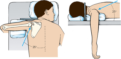
• Place a vertically supported IR against the superior aspect of the shoulder with the edge of the IR in contact with the neck.
Structures shown: The resulting image shows bony abnormalities of the anterior inferior rim of the glenoid and Hill-Sachs defects of the posterolateral humeral head in patients with chronic instability of the shoulder (Fig. 5-33).
• Place the IR near the end of the table and parallel with its long axis.
• Have the patient lean laterally over the IR until the shoulder joint is over the midpoint of the IR.
• Bring the elbow to rest on the table.
• Flex the patient’s elbow 90 degrees, and place the hand in the prone position (Fig. 5-34).
• Have the patient tilt the head toward the unaffected shoulder.
• To obtain direct lateral positioning of the head of the humerus, adjust any anterior or posterior leaning of the body to place the humeral epicondyles in the vertical position.
Structures shown: A superoinferior axial image shows the joint relationship of the proximal end of the humerus and the glenoid cavity (Fig. 5-35). The AC articulation, the outer portion of the coracoid process, and the points of insertion of the subscapularis muscle (at body of scapula) and teres minor muscle (at inferior axillary border) are shown.
Scapular Y
RAO or LAO position
This projection, described by Rubin et al.,1 obtained its name as a result of the appearance of the scapula. The body of the scapula forms the vertical component of the Y, and the acromion and coracoid processes form the upper limbs. This projection is useful in the evaluation of suspected shoulder dislocations.
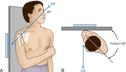
• Position the anterior surface of the shoulder being examined against the upright table.
• Rotate the patient so that the midcoronal plane forms an angle of 45 to 60 degrees to the IR. The position of the arm is not critical because it does not alter the relationship of the humeral head to the glenoid cavity (Fig. 5-36). Palpate the scapula, and place its flat surface perpendicular to the IR. According to Johnson et al.,1 this is accomplished by orienting the plane through the superior angle of the scapula and acromial tip, perpendicular to the IR.
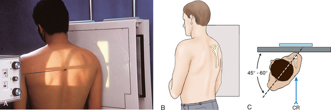
Fig. 5-36 A, PA oblique shoulder joint. B, Perspective from x-ray tube showing scapula centered in true lateral position. C, Top-down view showing positioning landmarks used for proper orientation of scapular body.
• Position the center of the IR at the level of the scapulohumeral joint.
COMPENSATING FILTER
Use of a specially designed compensating filter for the shoulder improves the quality of the image because of the large amount of primary beam radiation striking the IR. These filters are particularly useful when digital imaging (CR or DR) systems are used with this projection.
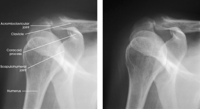
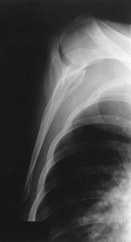
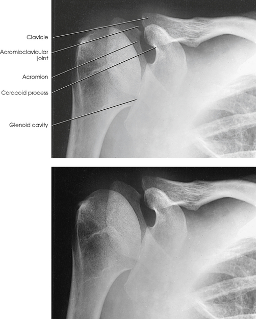
Structures shown: The scapular Y is shown on an oblique image of the shoulder. In the normal shoulder, the humeral head is directly superimposed over the junction of the Y (Fig. 5-37). In anterior (subcoracoid) dislocations, the humeral head is beneath the coracoid process (Fig. 5-38); in posterior (subacromial) dislocations, it is projected beneath the acromion process. An AP shoulder projection is shown for comparison (Fig. 5-39).
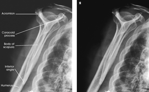
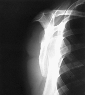
Fig. 5-38 PA oblique shoulder joint showing anterior dislocation (humeral head projected beneath coracoid process).
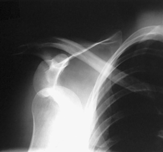
Fig. 5-39 AP shoulder (same patient as in Fig. 5-38).
The following should be clearly shown:
Evidence of proper collimation
Humeral head and glenoid cavity superimposed
Humeral shaft and scapular body superimposed
No superimposition of the scapular body over the bony thorax
Acromion projected laterally and free of superimposition
Coracoid possibly superimposed or projected below the clavicle
Scapula in lateral profile with lateral and vertebral borders superimposed
Supraspinatus “Outlet”
RAO or LAO position
This radiographic projection is useful to show tangentially the coracoacromial arch or outlet to diagnose shoulder impingement.1,2 The tangential image is obtained by projecting the x-ray beam under the acromion and AC joint, which defines the superior border of the coracoacromial outlet.
• With the patient’s affected shoulder centered and in contact with the IR, rotate the patient’s unaffected side away from the IR. Palpate the flat aspect of the affected scapula and place it perpendicular to the IR. The degree of patient obliquity varies from patient to patient. The average degree of patient rotation varies from 45 to 60 degrees from the plane of the IR (Fig. 5-40).
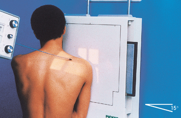
• Angled 10 to 15 degrees caudad, entering the superior aspect of the humeral head (see Table 5-3)
Structures shown: The tangential outlet image shows the posterior surface of the acromion and the AC joint identified as the superior border of the coracoacromial outlet (Figs. 5-41 and 5-42).
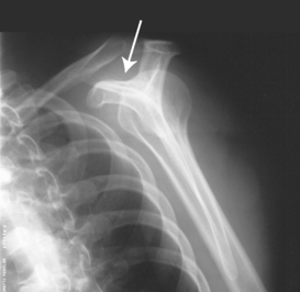
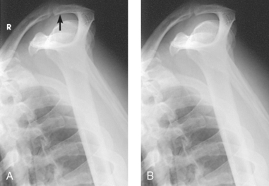
Fig. 5-42 A, Tangential supraspinatus outlet projection showing impingement of shoulder outlet by subacromial spur (arrow). B, Radiograph of same patient as in Fig. 5-41 after surgical removal of posterolateral surface of clavicle.
AP AXIAL PROJECTION
Proximal Humerus
Anterior dislocations of the shoulder frequently result in posterior defects involving the posterolateral head of the humerus. Such defects, called Hill-Sachs defects,1 are often not shown using conventional radiographic positions. Hall et al.2 described the notch projection, from ideas expressed by Stryker, as being useful to show this humeral defect.
• With the coracoid process of the affected shoulder centered to the table, ask the patient to flex the arm slightly beyond 90 degrees and place the palm of the hand on top of the head with fingertips resting on the head. (This hand position places the humerus in a slight internal rotation position.) The body of the humerus is adjusted to be vertical so that it is parallel to the midsagittal plane of the body (Fig. 5-45).
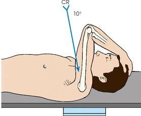
Structures shown: The resulting image shows the posterosuperior and posterolateral areas of the humeral head (Figs. 5-46 and 5-47).
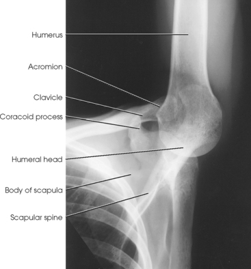
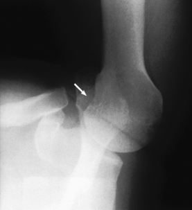
Fig. 5-47 Same projection as in Fig. 5-46 in a patient with small Hill-Sachs defect (arrow).
Glenoid Cavity
RPO or LPO position
This projection is recommended for acute shoulder trauma and for identifying posterior scapulohumeral dislocations, glenoid fractures, Hill-Sachs lesions, and soft tissue calcifications.1
• Center the IR to the glenohumeral joint.
• Rotate the body approximately 45 degrees toward the affected side.
• The posterior surface of the affected side is closest to the IR.
• Flex the elbow of the affected arm and place arm across the chest (Fig. 5-48).
Structures shown: The scapulohumeral joint, humeral head, coracoid process, and scapular head and neck are shown (Fig. 5-49).
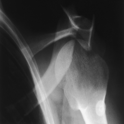
Fig. 5-49 AP axial oblique: Garth method showing anterior dislocation of proximal humerus. Humeral head is shown below coracoid process, a common appearance with anterior dislocation. (Courtesy Bruce W. Long, MS, RT[R][CV], and John A. Rafert, MS, RT[R].)
RESEARCH: Catherine E. Hearty, MS, RT(R), performed the research and provided this new projection for this edition of the atlas.
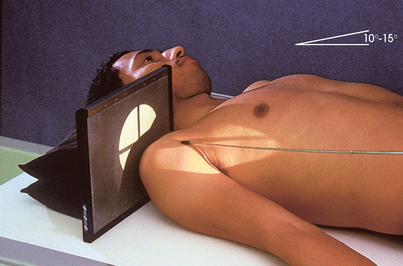
Intertubercular Groove
In recent years, various modifications of the intertubercular groove image have been devised. In all cases, the central ray is aligned to be tangential to the intertubercular groove, which lies on the anterior surface of the humerus.1
The x-ray tube head assembly may limit the performance of this examination. Some radiographic units have large collimators or handles, or both, that limit flexibility in positioning. A mobile radiographic unit may be used to reduce this difficulty.
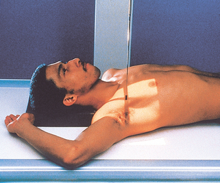
• With the patient supine, palpate the anterior surface of the shoulder to locate the intertubercular groove.
• With the patient’s hand in the supinated position, place the IR against the superior surface of the shoulder and immobilize the IR as shown in Fig. 5-50.
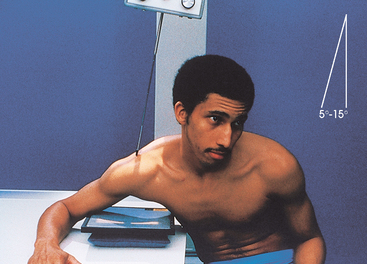
Fisk modification Fisk first described this position with the patient standing at the end of the radiographic table. This employs a greater OID. The following steps are then taken with Fisk’s technique:
• Instruct the patient to flex the elbow and lean forward far enough to place the posterior surface of the forearm on the table. The patient supports and grasps the IR as depicted in Fig. 5-51.
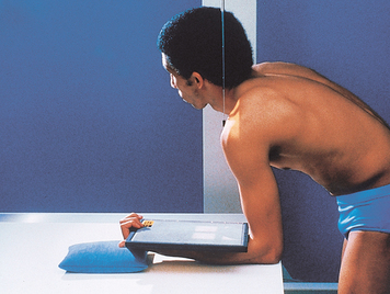
• For radiation protection and to reduce backscatter to the film from the forearm, place a lead shielding between the IR back and the forearm.
• Place a sandbag under the hand to place the IR horizontal.
• Have the patient lean forward or backward as required to place the vertical humerus at an angle of 10 to 15 degrees.
• Angled 10 to 15 degrees posterior (downward from horizontal) to the long axis of the humerus for the supine position (see Fig. 5-50)
• Perpendicular to the IR when the patient is leaning forward and the vertical humerus is positioned 10 to 15 degrees (see Fig. 5-51)
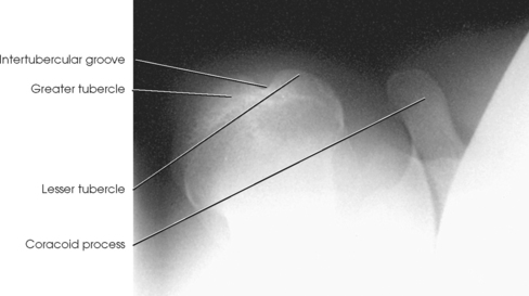
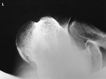
Structures shown: The tangential image profiles the intertubercular groove free from superimposition of the surrounding shoulder structures (Figs. 5-52 and 5-53).
Acromioclavicular Articulations
Bilateral
Image receptor: 7 × 17 inch (18 × 43 cm) or two 8 × 10 inch (18 × 24 cm), as needed to fit the patient
SID: 72 inches (183 cm). A longer SID reduces magnification, which enables both joints to be included on one image. It also reduces the distortion of the joint space resulting from central ray divergence.
• Place the patient in the upright position before a vertical grid device, and adjust the height of the IR so that the midpoint of the IR lies at the same level as the AC joints (Fig. 5-54).
• Center the midline of the body to the midline of the grid.
• Ensure that the weight of the body is equally distributed on the feet to avoid rotation.
• With the patient’s arms hanging by the sides, adjust the shoulders to lie in the same horizontal plane. It is important that the arms hang unsupported.
• Make two exposures: one in which the patient is standing upright without weights attached, and a second in which the patient has equal weights (5 to 10 lb) affixed to each wrist.1,2
• After the first exposure, slowly affix the weights to the patient’s wrist, using a band or strap.
• Instruct the patient not to favor (tense up) the injured shoulder.
• Avoid having the patient hold weights in each hand; this tends to make the shoulder muscles contract, reducing the possibility of showing a small AC separation (Fig. 5-55).
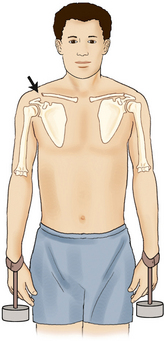
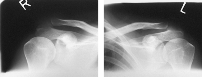
Fig. 5-55 Weights should be attached to wrists as shown and not held in hands. Note how separation of AC joint is shown by pulling of weights.
• Shield gonads. Also use a thyroid collar because the thyroid gland is exposed to the primary beam.
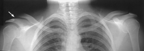
Structures shown: Bilateral images of the AC joints are shown (Figs. 5-56 and 5-57). This projection is used to show dislocation, separation, and function of the joints.
The following should be clearly shown:
Evidence of proper collimation
AC joints visualized with some soft tissue and without excessive density
Both AC joints, with and without weights, entirely included on one or two single radiographs
No rotation or leaning by the patient
Right or left and weight or nonweight markers
Separation, if done, clearly seen on the images with weights
AP AXIAL PROJECTION
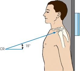
Alexander1 suggested that AP and PA axial oblique projections be used in cases of suspected AC subluxation or dislocation. Each side is examined separately.
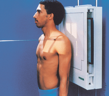
• Have the patient place the back against the vertical grid device and sit or stand upright.
• Center the affected shoulder under examination to the grid.
• Adjust the height of the IR so that the midpoint of the film is at the level of the AC joint.
• Adjust the patient’s position to center the coracoid process to the IR (Fig. 5-58).
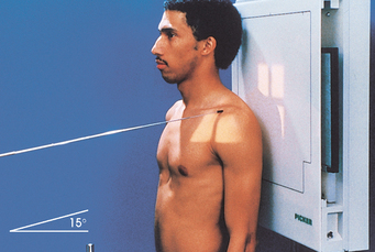
• Directed to the coracoid process at a cephalic angle of 15 degrees (Fig. 5-59). This angulation projects the AC joint above the acromion.
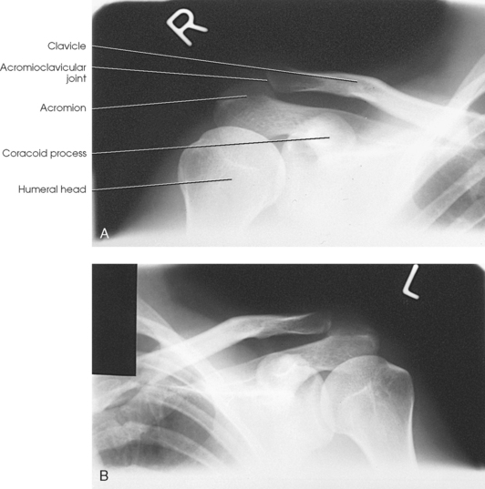
Structures shown: The resulting image shows the AC joint projected slightly superiorly compared with an AP projection (Fig. 5-60).
Clavicle
• Adjust the body to center the clavicle to the midline of the table or vertical grid device.
• Place the arms along the sides of the body, and adjust the shoulders to lie in the same horizontal plane.
• Center the clavicle to the IR (Fig. 5-61).
• Respiration: Suspend at the end of exhalation to obtain a more uniform-density image.
AP AXIAL PROJECTION
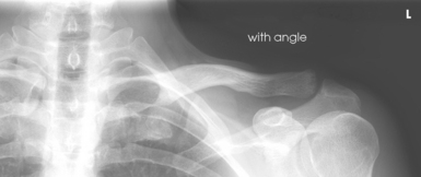
NOTE: If the patient is injured or unable to assume the lordotic position, a slightly distorted image results when the tube is angled. An optional approach for improved recorded detail is the PA axial projection.
• Temporarily support the patient in the lordotic position to estimate the required central ray angulation, and have the patient reassume the upright position while the equipment is adjusted.
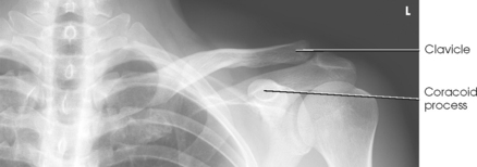
• Have the patient lean backward in a position of extreme lordosis, and rest the neck and shoulder against the vertical grid device. The neck is in extreme flexion (Figs. 5-63 and 5-64).
• Center the clavicle to the center of the IR (see Fig. 5-64).
• Directed to enter the midshaft of the clavicle
• Cephalic central ray angulation can vary from the long axis of the torso; thinner patients require more angulation to project the clavicle off the scapula and ribs
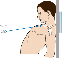
• For the standing lordotic position, 0 to 15 degrees is recommended (see Fig. 5-63).
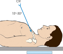
• For the supine position, 15 to 30 degrees is recommended (see Fig. 5-64).
PA PROJECTION
The PA projection is generally well accepted by the patient who can stand, and it is most useful when improved recorded detail is desired. The advantage of the PA projection is that the clavicle is closer to the image receptor, reducing the OID. Positioning is similar to that of the AP projection. The differences are as follows:
• The patient is standing upright (back toward the x-ray tube) or prone (Fig. 5-66).
• The perpendicular central ray exits the midshaft of the clavicle (Fig. 5-67).
Structures shown and evaluation criteria are the same as for the AP projection.
PA AXIAL PROJECTION
Positioning of the PA axial clavicle is similar to the AP axial projection described previously. The differences are as follows:
• The patient is prone or standing, facing the vertical grid device.
• The central ray is angled 15 to 30 degrees caudad (Fig. 5-68).
Structures shown and evaluation criteria are the same as for the AP axial projection described previously.
Scapula
• Adjust the patient’s body, and center the affected scapula to the midline of the grid.
• Abduct the arm to a right angle with the body to draw the scapula laterally. Flex the elbow, and support the hand in a comfortable position.
• For this projection, do not rotate the body toward the affected side because the resultant obliquity would offset the effect of drawing the scapula laterally (Fig. 5-69).
• Position the top of the IR 2 inches (5 cm) above the top of the shoulder.
• Respiration: Make this exposure during slow breathing to obliterate lung detail.
Structures shown: An AP projection of the scapula is shown (Fig. 5-70).
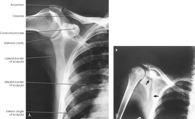
Fig. 5-70 A, AP scapula. B, AP scapula showing fracture of scapula through glenoid cavity and extending inferiorly (arrows).
LATERAL PROJECTION
• Adjust the patient in RAO or LAO position, with the affected scapula centered to the grid. The average patient requires a 45- to 60-degree rotation from the plane of the IR. According to Johnston et al.,1 the proper patient rotation is accomplished by orienting the plane through the superior angle of the scapula and acromial tip, perpendicular to the IR.
• Place the arm in one of two positions according to the area of the scapula to be shown.
• For delineation of the acromion and coracoid processes of the scapula, have the patient flex the elbow and place the back of the hand on the posterior thorax at a level sufficient to prevent the humerus from overlapping the scapula (Figs. 5-71 and 5-72). Mazujian1 suggested that the patient place the arm across the upper chest by grasping the opposite shoulder, as shown in Fig. 5-73.
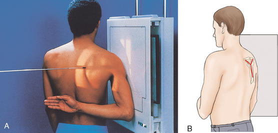
Fig. 5-71 A, Lateral scapula, RAO body position. B, Perspective from x-ray tube showing scapula centered in true lateral position.
• To show the body of the scapula, ask the patient to extend the arm upward and rest the forearm on the head or across the upper chest by grasping the opposite shoulder (Fig. 5-74; see Fig. 5-73).
• After placing the arm in any of these positions, grasp the lateral and medial borders of the scapula between the thumb and index fingers of one hand. Make a final adjustment of the body rotation, placing the body of the scapula perpendicular to the plane of the IR.
COMPENSATING FILTER
Use of a specially designed compensating filter for the shoulder improves the quality of the image because of the large amount of primary beam radiation striking the IR. These filters are particularly useful when digital radiography (CR or DR) systems are used with this projection.
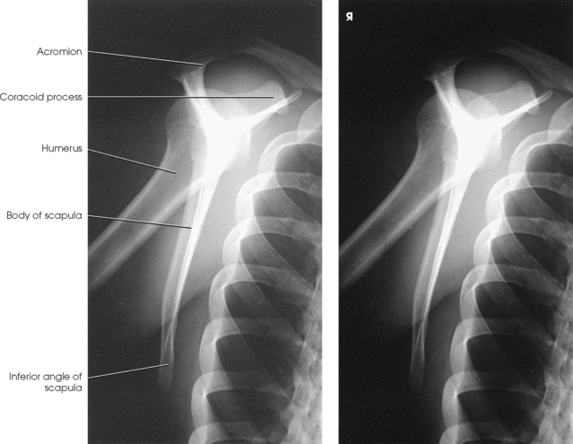
Structures shown: A lateral image of the scapula is shown by this projection. The placement of the arm determines the portion of the superior scapula that is superimposed over the humerus.
The following should be clearly shown:
Lateral and medial borders superimposed
No superimposition of the scapular body on the ribs
No superimposition of the humerus on the area of interest
NOTE: For trauma patients, this projection can be performed using the LPO or RPO position (see Fig. 13-42 in Volume 2).
AP OBLIQUE PROJECTION
• Align the body and center the affected scapula to the midline of the grid.
• For moderate AP oblique projection, ask the patient to extend the arm superiorly, flex the elbow, and place the supinated hand under the head, or have the patient extend the affected arm across the anterior chest.
• Have the patient turn away from the affected side enough to rotate the shoulder 15 to 25 degrees (Fig. 5-75).
• For a steeper oblique projection, ask the patient to extend the arm, rest the flexed elbow on the forehead, and rotate the body away from the affected side 25 to 35 degrees (Fig. 5-76).
• Grasp the lateral and medial borders of the scapula between the thumb and index fingers of one hand, and adjust the rotation of the body to project the scapula free of the rib cage.
• For a direct lateral projection of the scapula using this position, draw the arm across the chest, and adjust the body rotation to place the scapula perpendicular to the plane of the IR as previously described and shown in Figs. 5-71 to 5-74.
Structures shown: This projection shows oblique images of the scapula, projected free or nearly free of rib superimposition (Figs. 5-77 and 5-78).
Coracoid Process
• Adjust the position of the body, and center the affected coracoid process to the midline of the grid.
• Position the IR so that the midpoint of the IR coincides with the central ray.
• Adjust the shoulders to lie in the same horizontal plane.
• Abduct the arm of the affected side slightly, and supinate the hand, immobilizing it with a sandbag across the palm (Fig. 5-79).
• Respiration: Suspend at the end of exhalation for a more uniform density.
• Directed to enter the coracoid process at an angle of 15 to 45 degrees cephalad. Kwak et al.1 recommended an angle of 30 degrees. The degree of angulation depends on the shape of the patient’s back. Round-shouldered patients require a greater angulation than patients with a straight back (Fig. 5-80).
Structures shown: A slightly elongated inferosuperior image of the coracoid process is illustrated (Fig. 5-81). Because the coracoid is curved on itself, it casts a small, oval shadow in the direct AP projection of the shoulder.
Scapular Spine
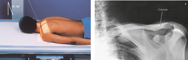
LAQUERRIÈRE-PIERQUIN METHOD
• As described by Laquerrière and Pierquin,1 place the patient in the supine position.
• Center the shoulder to the midline of the grid.
• Adjust the patient’s rotation to place the body of the scapula in a horizontal position. When this requires elevation of the opposite shoulder, support it on sandbags or radiolucent sponges.
• Turn the head away from the shoulder being examined, enough to prevent superimposition (Fig. 5-82).
Structures shown: The spine of the scapula is shown in profile and is free of bony superimposition except for the lateral end of the clavicle (Figs. 5-83 and 5-84).
The following should be clearly shown:
Scapular spine superior to the scapular body
Scapular spine with some soft tissue around it and without excessive density
NOTE: When the shoulder is too painful to tolerate the supine position, this projection can be obtained with the patient in the prone or upright position.
*NOTE: These landmarks are recommended by Johnston et al.1 as useful to identify the plane through the scapular body.
1Johnston J et al: Landmarks for lateral scapula and scapular Y positioning, Radiol Technol 79:397, 2008.
1Apple A et al: The weighted abduction Grashey shoulder method, Radiol Technol 69:151, 1997.
1Lawrence WS: A method of obtaining an accurate lateral roentgenogram of the shoulder joint, AJR Am J Roentgenol 5:193, 1918.
1Lawrence WS: A method of obtaining an accurate lateral roentgenogram of the shoulder joint, AJR Am J Roentgenol 5:193, 1918.
1Rafert JA et al: Axillary shoulder with exaggerated rotation: the Hill-Sachs defect, Radiol Technol 62:18, 1990.
1Hill H, Sachs M: The grooved defect of the humeral head: a frequently unrecognized complication of dislocations of the shoulder joint, Radiology 35:690, 1940.
1Rokous JR et al: Modified axillary roentgenogram, Clin Orthop Relat Res 82:84, 1972.
1Rubin SA et al: The scapular Y: a diagnostic aid in shoulder trauma, Radiology 110:725, 1974.
1Johnston J et al: Landmarks for lateral scapula and scapular Y positioning, Radiol Technol 79:397, 2008.
1Neer CS II: Supraspinatus outlet, Orthop Trans 11:234, 1987.
2Neer CS II: Shoulder reconstruction, Philadelphia, 1990, Saunders, pp 14-24.
1Hill H, Sachs M: The grooved defect of the humeral head: a frequently unrecognized complication of dislocations of the shoulder joint, Radiology 35:690, 1940.
2Hall RH et al: Dislocations of the shoulder with special reference to accompanying small fractures, J Bone Joint Surg Am 41:489, 1959.
1Garth W et al: Roentgenographic demonstration of instability of the shoulder: the apical oblique projection, J Bone Joint Surg Am 66:1450, 1984.
1Fisk C: Adaptation of the technique for radiography of the bicipital groove, Radiol Technol 34:47, 1965.
1Allman FL. Fractures and ligamentous injuries of the clavicle and its articulations, J Bone Joint Surg Am 49:774, 1967.
2Rockwood CA, Green DP: Fractures in adults, ed 7, Philadelphia, 2009, Lippincott.
1Alexander OM: Radiography of the acromioclavicular articulation, Med Radiogr Photogr 30:34, 1954.
1Johnston J et al: Landmarks for lateral scapula and scapular Y positioning, Radiol Technol 79:397, 2008.
1Mazujian M: Lateral profile view of the scapula, Xray Techn 25:24, 1953.
1Kwak DL et al: Angled anteroposterior views of the shoulder, Radiol Technol 53:590, 1982.
1Laquerrière, Pierquin: De la nécessité d’employer une technique radiographique spéciale pour obtenir certains details squelettiques, J Radiol Electr 3:145, 1918.