PELVIS AND UPPER FEMORA
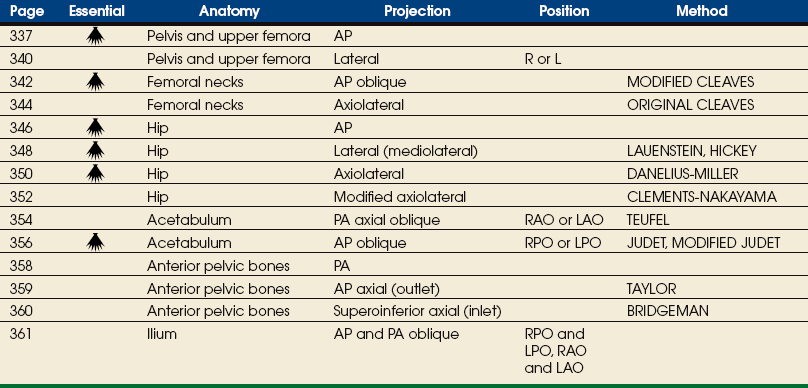
SUMMARY OF PROJECTIONS
ANATOMY
The pelvis serves as a base for the trunk and a girdle for the attachment of the lower limbs. The pelvis consists of four bones: two hip bones, the sacrum, and the coccyx. The pelvic girdle is composed of only the two hip bones.
Hip Bone
The hip bone is often referred to as the os coxae, and some textbooks continue to refer to it as the innominate bone. The most widely used term is hip bone.
The hip bone consists of the ilium, pubis, and ischium (Figs. 7-1 and 7-2). These three bones join together to form the acetabulum, the cup-shaped socket that receives the head of the femur. The ilium, pubis, and ischium are separated by cartilage in children but become fused into one bone in adults.
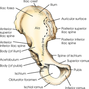
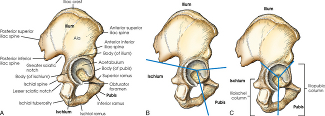
Fig. 7-2 A, Lateral aspect of right hip bone. B, Lateral aspect of right hip bone showing its three parts. C, Lateral aspect of hip bone showing ilioischial and iliopubic columns.
The hip bone is divided further into two distinct areas: the iliopubic column and the ilioischial column (see Fig. 7-2, C). These columns are used to identify fractures around the acetabulum.
ILIUM
The ilium consists of a body and a broad, curved portion called the ala. The body of the ilium forms approximately two fifths of the acetabulum superiorly (Fig. 7-3). The ala projects superiorly from the body to form the prominence of the hip. The ala has three borders: anterior, posterior, and superior. The anterior and posterior borders present four prominent projections:
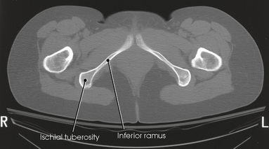
Fig. 7-3 Axial CT image of inferior ramus and ischial tuberosity. (Modified from Kelley L, Petersen CM: Sectional anatomy for imaging professionals, ed 2, St Louis, 2007, Mosby.)
The anterior superior iliac spine (ASIS) is an important and frequently used radiographic positioning reference point. The superior margin extending from the ASIS to the posterior superior iliac spine is called the iliac crest. The medial surface of the wing contains the iliac fossa and is separated from the body of the bone by a smooth, arc-shaped ridge, the arcuate line, which forms a part of the circumference of the pelvic brim. The arcuate line passes obliquely, inferiorly, and medially to its junction with the pubis. The inferior and posterior portions of the wing present a large, rough surface—the auricular surface—for articulation with the sacrum. This articular surface and the articular surface of the adjacent sacrum have irregular elevations and depressions that cause a partial interlock of the two bones. The ilium curves inward below this surface, forming the greater sciatic notch.
PUBIS
The pubis consists of a body, the superior ramus, and the inferior ramus. The body of the pubis forms approximately one fifth of the acetabulum anteriorly (see Fig. 7-2). The superior ramus projects inferiorly and medially from the acetabulum to the midline of the body. There the bone curves inferiorly and then posteriorly and laterally to join the ischium. The lower prong is termed the inferior ramus.
ISCHIUM
The ischium consists of a body and the ischial ramus. The body of the ischium forms approximately two fifths of the acetabulum posteriorly (see Figs. 7-2 and 7-3). It projects posteriorly and inferiorly from the acetabulum to form an expanded portion called the ischial tuberosity. When the body is in a seated-upright position, its weight rests on the two ischial tuberosities. The ischial ramus projects anteriorly and medially from the tuberosity to its junction with the inferior ramus of the pubis. By this posterior union the rami of the pubis and ischium enclose the obturator foramen. At the superoposterior border of the body is a prominent projection called the ischial spine. An indentation, the lesser sciatic notch, is just below the ischial spine.
Proximal Femur
The femur is the longest, strongest, and heaviest bone in the body. The proximal end of the femur consists of a head, a neck, and two large processes: the greater and lesser trochanters (Fig. 7-4). The smooth, rounded head is connected to the femoral body by a pyramid-shaped neck and is received into the acetabular cavity of the hip bone. A small depression at the center of the head, the fovea capitis, attaches to the ligamentum capitis femoris (Fig. 7-5; see Fig. 7-4). The neck is constricted near the head but expands to a broad base at the body of the bone. The neck projects medially, superiorly, and anteriorly from the body. The trochanters are situated at the junction of the body and the base of the neck. The greater trochanter is at the superolateral part of the femoral body, and the lesser trochanter is at the posteromedial part. The prominent ridge extending between the trochanters at the base of the neck on the posterior surface of the body is called the intertrochanteric crest. The less prominent ridge connecting the trochanters anteriorly is called the intertrochanteric line. The femoral neck and the intertrochanteric crest are two common sites of fractures in elderly adults. The superior portion of the greater trochanter projects above the neck and curves slightly posteriorly and medially.
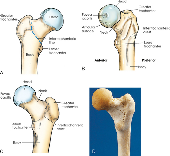
Fig. 7-4 Proximal right femur. A, Anterior aspect. B, Medial aspect. The body is positioned 15 to 20 degrees posterior from head. C, Posterior aspect. D, Posterior aspect of right proximal human femur. Note anatomic details and compare with C.
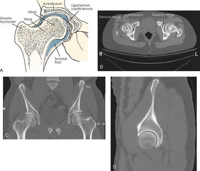
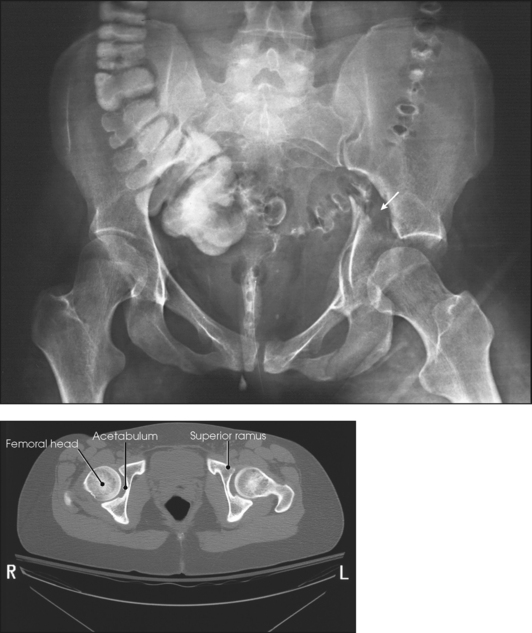
Fig. 7-5 A, Hip joint. Coronal section of proximal femur in acetabulum. B, Axial CT image of hip joint showing acetabulum, head of femur, and superior ramus. C, Coronal CT image of both hip joints. D, Sagittal CT image of the right hip joint. (Modified from Kelley L, Petersen CM: Sectional anatomy for imaging professionals, ed 2, St Louis, 2007, Mosby.)
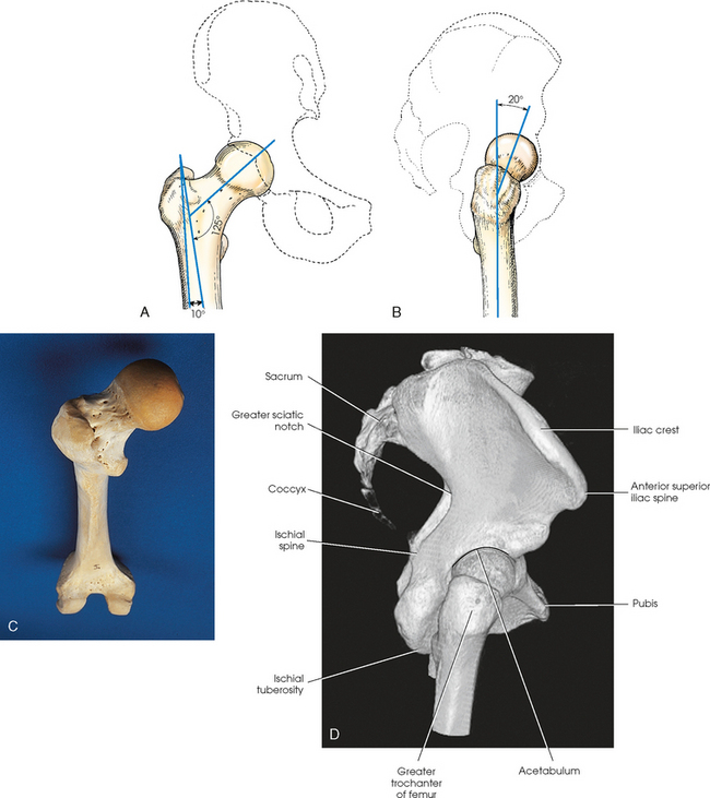
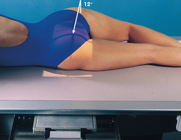
The angulation of the neck of the femur varies considerably with age, sex, and stature. In the average adult, the neck projects anteriorly from the body at an angle of approximately 15 to 20 degrees and superiorly at an angle of approximately 120 to 130 degrees to the long axis of the femoral body (Fig. 7-6). The longitudinal plane of the femur is angled about 10 degrees from vertical. In children, the latter angle is wider—that is, the neck is more vertical in position. In wide pelves, the angle is narrower, placing the neck in a more horizontal position.
Articulations of the Pelvis
Table 7-1 and Fig. 7-7 provide a summary of the three joints of the pelvis and upper femora. The articulation between the acetabulum and the head of the femur (the hip joint) is a synovial ball-and-socket joint that permits free movement in all directions. The knee and ankle joints are hinge joints; the wide range of motion of the lower limb depends on the ball-and-socket joint of the hip. Because the knee and ankle joints are hinge joints, medial and lateral rotations of the foot cause rotation of the entire limb, which is centered at the hip joint.
TABLE 7-1
Joints of the pelvis and upper femora

*Some anatomists term this a synovial fibrous joint.
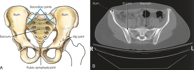
Fig. 7-7 A, Joints of pelvis and upper femora. B, Axial CT image of pelvis showing SI joints. Note 25- to 30-degree angulation of joint. (B, Modified from Kelley L, Petersen CM: Sectional anatomy for imaging professionals, ed 2, St Louis, 2007, Mosby.)
The pubes of the hip bones articulate with each other at the anterior midline of the body, forming a joint called the pubic symphysis. The pubic symphysis is a cartilaginous symphysis joint.
The right and left ilia articulate with the sacrum posteriorly at the sacroiliac (SI) joints. These two joints angle 25 to 30 degrees relative to the midsagittal plane (see Fig. 7-7, B). The SI articulations are synovial irregular gliding joints. Because the bones of the SI joints interlock, movement is limited or nonexistent.
Pelvis
The female pelvis (Fig. 7-8) is lighter in structure than the male pelvis (Fig. 7-9). It is wider and shallower, and the inlet is larger and more oval-shaped. The sacrum is wider, it curves more sharply posteriorly, and the sacral promontory is flatter. The width and depth of the pelvis vary with stature and gender (Table 7-2). The female pelvis is shaped for childbearing and delivery.
TABLE 7-2
Female and male pelvis characteristics
| Feature | Female | Male |
| Shape | Wide, shallow | Narrow, deep |
| Bony structure | Light | Heavy |
| Superior aperture (inlet) | Oval | Round |
| Inferior aperture (outlet) | Wide | Narrow |
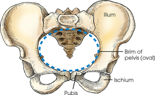
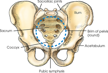
The pelvis is divided into two portions by an oblique plane that extends from the upper anterior margin of the sacrum to the upper margin of the pubic symphysis. The boundary line of this plane is called the brim of the pelvis (see Figs. 7-8 and 7-9). The region above the brim is called the false or greater pelvis, and the region below the brim is called the true or lesser pelvis.
The brim forms the superior aperture, or inlet, of the true pelvis. The inferior aperture, or outlet, of the true pelvis is measured from the tip of the coccyx to the inferior margin of the pubic symphysis in the anteroposterior direction and between the ischial tuberosities in the horizontal direction. The region between the inlet and the outlet is called the pelvic cavity (Fig. 7-10).
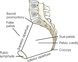
When the body is in the upright or seated position, the brim of the pelvis forms an angle of approximately 60 degrees to the horizontal plane. This angle varies with other body positions; the degree and direction of the variation depend on the lumbar and sacral curves.
Localizing Anatomic Structures
The bony landmarks used in radiography of the pelvis and hips are as follows:
Most of these points are easily palpable, even in hypersthenic patients (Fig. 7-11). Because of the heavy muscles immediately above the iliac crest, care must be exercised in locating this structure to avoid centering errors. Having the patient inhale deeply is advisable; while the muscles are relaxed during expiration, the radiographer should palpate for the highest point of the iliac crest.
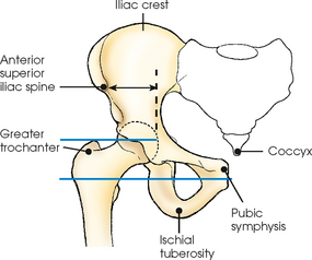
The highest point of the greater trochanter, which can be palpated immediately below the depression in the soft tissues of the lateral surface of the hip, is in the same horizontal plane as the midpoint of the hip joint and the coccyx. The most prominent point of the greater trochanter is in the same horizontal plane as the pubic symphysis (see Fig. 7-11).
The greater trochanter is most prominent laterally and more easily palpated when the lower leg is medially rotated. When properly used, medial rotation assists in localization of hip and pelvis centering points and avoids distortion of the proximal end of the femur during radiography. Improper rotation of the lower leg can rotate the pelvis. Consequently, positioning of the lower leg is important in radiographing the hip and pelvis; the feet must be immobilized in the correct position to avoid distortion of the image. Traumatic injuries or pathologic conditions of the pelvis or lower limb may rule out the possibility of medial rotation.
The pubic symphysis can be palpated on the midsagittal plane and on the same horizontal plane as the greater trochanters. By placing the fingertips at this location and performing a brief downward palpation with the hand flat, palm down, and fingers together, the radiographer can locate the superior margin of the pubic symphysis. To avoid possible embarrassment or misunderstanding, the radiographer should advise the patient in advance that this and other palpations of pelvic landmarks are part of normal procedure and necessary for an accurate examination. When performed in an efficient and professional manner with respect for the patient’s condition, such palpations are generally well tolerated.
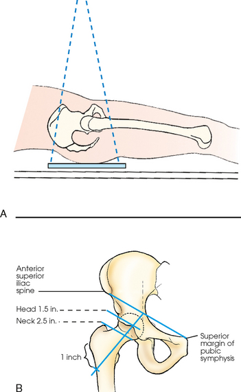
The hip joint can be located by palpating the ASIS and the superior margin of the pubic symphysis (Fig. 7-12). The midpoint of a line drawn between these two points is directly above the center of the dome of the acetabular cavity. A line drawn at right angles to the midpoint of the first line lies parallel to the long axis of the femoral neck of an average adult in the anatomic position. The femoral head lies 1½ inches (3.8 cm) distal, and the femoral neck is 2½ (6.4 cm) distal to this point.
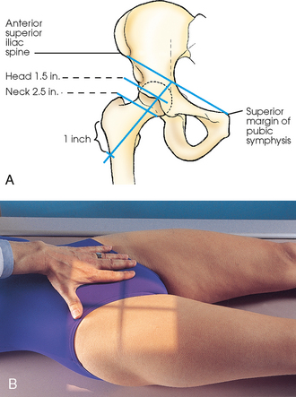
Fig. 7-12 A, Method of localizing right hip joint and long axis of femoral neck. B, Suggested method of localizing right hip. Left thumb is on ASIS, and second finger is on superior margin of pubic symphysis. Central ray is positioned 1.5 inches distal to center of line drawn between ASIS and pubic symphysis.
For accurate localization of the femoral neck in atypical patients or in patients in whom the limb is not in the anatomic position, a line is drawn between the ASIS and the superior margin of the pubic symphysis, and a second line is drawn from a point 1 inch (2.5 cm) inferior to the greater trochanter to the midpoint of the previously marked line. The femoral head and neck lies along this line (see Fig. 7-12).
ALTERNATIVE POSITIONING LANDMARK
Bello1 described an alternative positioning landmark for the pelvis and hip.
SUMMARY OF PATHOLOGY
| Condition | Definition |
| Ankylosing spondylitis | Rheumatoid arthritis variant involving the SI joints and spine |
| Congenital hip dysplasia | Malformation of the acetabulum causing displacement of the femoral head |
| Dislocation | Displacement of a bone from the joint space |
| Fracture | Disruption in the continuity of bone |
| Legg-Calvé-Perthes disease | Flattening of the femoral head owing to vascular interruption |
| Metastases | Transfer of a cancerous lesion from one area to another |
| Osteoarthritis or degenerative joint disease | Form of arthritis marked by progressive cartilage deterioration in synovial joints and vertebrae |
| Osteopetrosis | Increased density of atypically soft bone |
| Osteoporosis | Loss of bone density |
| Paget disease | Thick, soft bone marked by bowing and fractures |
| Slipped epiphysis | Proximal portion of femur dislocated from distal portion at the proximal epiphysis |
| Tumor | New tissue growth where cell proliferation is uncontrolled |
| Chondrosarcoma | Malignant tumor arising from cartilage cells |
| Multiple myeloma | Malignant neoplasm of plasma cells involving the bone marrow and causing destruction of the bone |
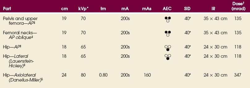
EXPOSURE TECHNIQUE CHART ESSENTIAL PROJECTIONS
RADIOGRAPHY
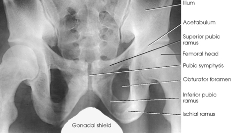
Protection of the patient from unnecessary radiation is a professional responsibility of the radiographer (see Chapter 1 for specific guidelines). In this chapter, the Shield gonads statement at the end of the Position of part section indicates that the patient is to be protected from unnecessary radiation by restricting the radiation beam using proper collimation. In addition, placing lead shielding between the gonads and the radiation source is appropriate when the clinical objectives of the examination are not compromised (Figs. 7-13 and 7-14).
Pelvis and Upper Femora
• Center the midsagittal plane of the body to the midline of the grid, and adjust it in a true supine position.
• Unless contraindicated because of trauma or pathologic factors, medially rotate the feet and lower limbs about 15 to 20 degrees to place the femoral necks parallel with the plane of the image receptor (IR) (Figs. 7-15 and 7-16). Medial rotation is easier for the patient to maintain if the knees are supported. The heels should be placed about 8 to 10 inches (20 to 24 cm) apart.
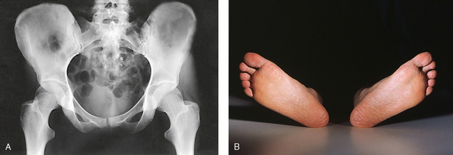
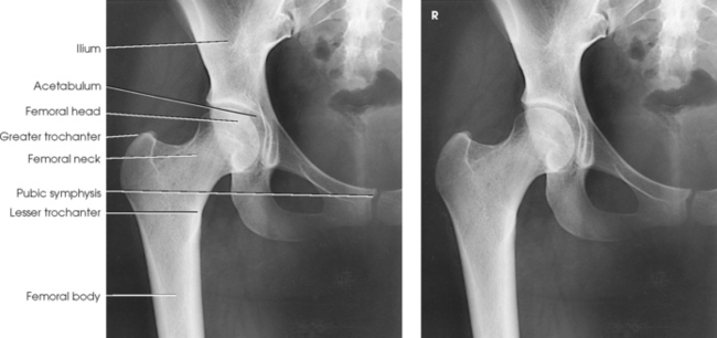
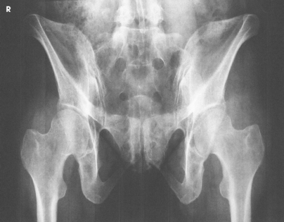
Fig. 7-15 A, AP pelvis with femoral necks and trochanters poorly positioned because of lateral rotation of limbs. B, Feet and lower limbs in natural, laterally rotated tabletop position, causing poor profile of proximal femora in A.
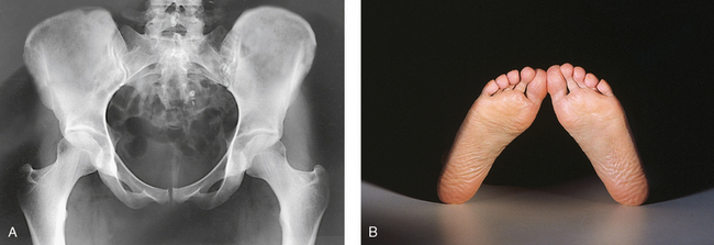
Fig. 7-16 A, AP pelvis with femoral necks and trochanters in correct position. B, Feet and lower limbs medially rotated 15 to 20 degrees, correctly placed with upper femora in correct profile in A.
• Immobilize the legs with a sandbag across the ankles, if necessary.
• Check the distance from ASIS to the tabletop on each side to be sure that the pelvis is not rotated.
• Center the IR midway between ASIS and pubic symphysis. In average-sized patients, the center of the IR is about 2 inches (5 cm) inferior to ASIS and 2 inches (5 cm) superior to pubic symphysis (Fig. 7-17).
• If the pelvis is deep, palpate for the iliac crest and adjust the position of the IR so that its upper border projects 1 to 1½ inches (2.5 to 3.8 cm) above the crest.
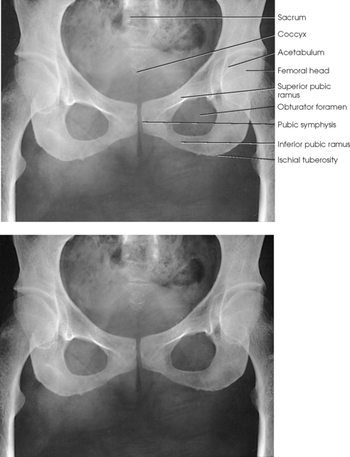
Structures shown: The image shows an AP projection of the pelvis and of the head, neck, trochanters, and proximal one third or one fourth of the shaft of the femora (Fig. 7-18).
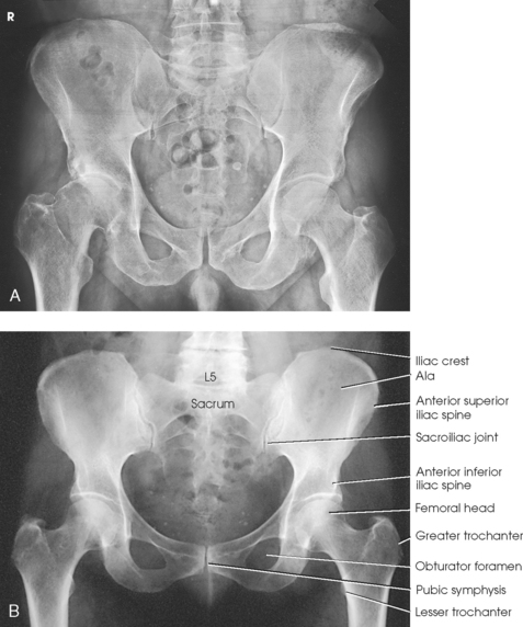
The following should be clearly shown:
 Evidence of proper collimation
Entire pelvis along with the proximal femora
Lesser trochanters, if seen, shown on the medial border of the femora
Femoral necks in their full extent without superimposition
Greater trochanters in profile
Both ilia equidistant to the edge of the radiograph
Both greater trochanters equidistant to the edge of the radiograph
Lower vertebral column centered to the middle of the radiograph
Congenital dislocation of the hip
Martz and Taylor1 recommended two AP projections of the pelvis to show the relationship of the femoral head to the acetabulum in patients with congenital dislocation of the hip. The first projection is obtained with the central ray directed perpendicular to the pubic symphysis to detect any lateral or superior displacement of the femoral head. The second projection is obtained with the central ray directed to the pubic symphysis at a cephalic angulation of 45 degrees (Fig. 7-19). This angulation casts the shadow of an anteriorly displaced femoral head above that of the acetabulum and the shadow of a posteriorly displaced head below that of the acetabulum.
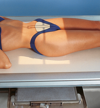
LATERAL PROJECTION
• When the patient can be placed in the lateral position, center the midcoronal plane of the body to the midline of the grid.
• Extend the thighs enough to prevent the femora from obscuring the pubic arch.
• Place a support under the lumbar spine, and adjust it to place the vertebral column parallel with the tabletop (Fig. 7-20). If the vertebral column is allowed to sag, it tilts the pelvis in the longitudinal plane.
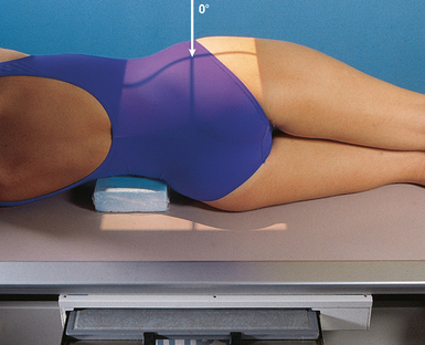
• Adjust the pelvis in a true lateral position, with ASIS lying in the same vertical plane.
• Place one knee directly over the other knee. A pillow or other support between the knees promotes stabilization and patient comfort.
• Berkebile et al.1 recommended a dorsal decubitus lateral projection of the pelvis to show the “gull-wing” sign in cases of fracture-dislocation of the acetabular rim and posterior dislocation of the femoral head.
• Place the patient in the lateral position in front of a vertical grid device, and center the midcoronal plane of the body to the midline of the grid.
• Have the patient stand straight, with the weight of the body equally distributed on the feet so that the midsagittal plane is parallel with the plane of the IR.
• If the limbs are of unequal length, place a support of suitable height under the foot of the short side.
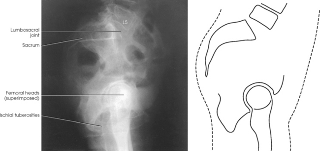
Structures shown: The resulting image shows a lateral radiograph of the lumbosacral junction, sacrum, coccyx, and superimposed hip bones and upper femora (Fig. 7-21).
Femoral Necks
This projection is often called the bilateral frog leg position.
NOTE: This examination is contraindicated for a patient suspected to have a fracture or other pathologic disease.
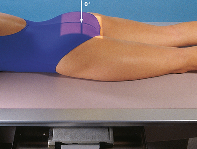
• Center the midsagittal plane of the body to the midline of the grid.
• Flex the patient’s elbows, and rest the hands on the upper chest.
• Adjust the patient so that the pelvis is not rotated. This position can be achieved by placing the two ASIS equidistant from the radiographic table.
• Place a compression band across the patient well above the hip joints for stability, if necessary.
Bilateral projection
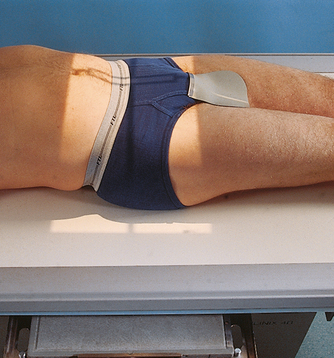
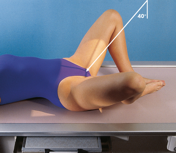
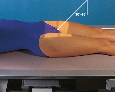
• Abduct the thighs as much as possible, and have the patient turn the feet inward to brace the soles against each other for support. According to Cleaves, the angle may vary between 25 degrees and 45 degrees, depending on how vertical the femora can be placed.
• Center the feet to the midline of the grid (Fig. 7-22).
• If possible, abduct the thighs approximately 45 degrees from the vertical plane to place the long axes of the femoral necks parallel with the plane of the IR.
• Check the position of the thighs, being careful to abduct them to the same degree.
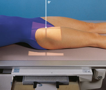
Unilateral projection
• Adjust the body position to center ASIS of the affected side to the midline of the grid.
• Have the patient flex the hip and knee of the affected side and draw the foot up to the opposite knee as much as possible.
• After adjusting the perpendicular central ray and positioning the IR tray, have the patient brace the sole of the foot against the opposite knee and abduct the thigh laterally approximately 45 degrees (Fig. 7-23). The pelvis may rotate slightly.
• Perpendicular to enter the patient’s midsagittal plane at the level 1 inch (2.5 cm) superior to the pubic symphysis. For the unilateral position, direct the central ray to the femoral neck (see Fig. 7-12).
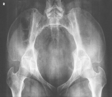
Structures shown: The bilateral image shows an AP oblique projection of the femoral heads, necks, and trochanteric areas projected onto one radiograph for comparison (Figs. 7-24 to 7-26).
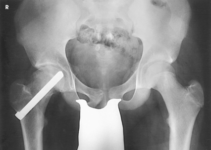
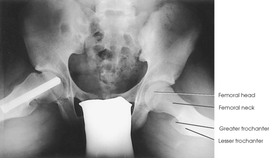
Fig. 7-25 AP oblique femoral necks: modified Cleaves method (same patient as in Fig. 7-24).
The following should be clearly shown:
Evidence of proper collimation
No rotation of the pelvis, as evidenced by a symmetric appearance
Acetabulum, femoral head, and femoral neck
Lesser trochanter on the medial side of the femur
Femoral neck without superimposition by the greater trochanter; excess abduction causes the greater trochanter to obstruct the neck.
AXIOLATERAL PROJECTION
ORIGINAL CLEAVES METHOD1
NOTE: This examination is contraindicated for patients with suspected fracture or pathologic condition.
Position of part: NOTE: This is the same part position as the modified Cleaves method previously described. The projection can be performed unilaterally or bilaterally.
• Parallel with the femoral shafts. According to Cleaves,1 the angle may vary between 25 degrees and 45 degrees, depending on how vertical the femora can be placed.
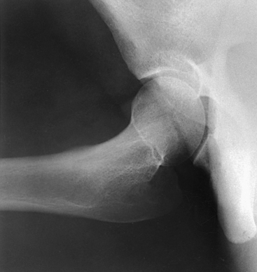
Structures shown: The resulting image shows an axiolateral projection of the femoral heads, necks, and trochanteric areas (Fig. 7-28).
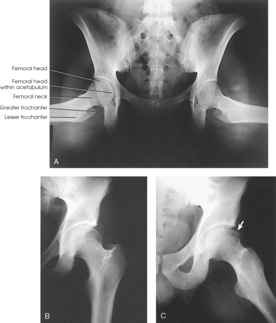
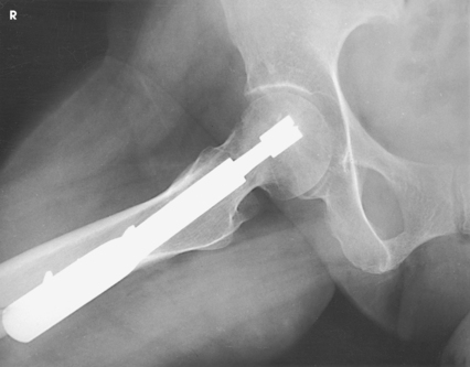
Fig. 7-28 Axiolateral femoral necks: Cleaves method. A, Bilateral examination. B and C, Unilateral hip examination of a patient who fell. No fractures were seen on initial AP hip radiograph (B), and a second projection using the Cleaves method was performed. Chip fracture of femoral head (arrow) was seen (C). At least two projections are required in trauma diagnoses.
The following should be clearly shown:
Axiolateral projections of the femoral necks
Femoral necks without overlap from the greater trochanters
Small parts of the lesser trochanters on the posterior surfaces of the femora
Small amount of the greater trochanters on the posterior and anterior surfaces of the femora
Both sides equidistant from the edge of the radiograph
Greater amount of the proximal femur on a unilateral examination
Femoral neck angles approximately 15 to 20 degrees superior to the femoral bodies
Congenital dislocation of the hip
The diagnosis of congenital dislocation of the hip in newborns has been discussed in numerous articles. Andren and von Rosén1 described a method that is based on certain theoretic considerations. Their method requires accurate and judicious application of the positioning technique to make an accurate diagnosis. The Andren-von Rosén approach involves taking a bilateral hip projection with both legs forcibly abducted to at least 45 degrees with appreciable inward rotation of the femora. Knake and Kuhns2 described the construction of a device that controlled the degree of abduction and rotation of both limbs. They reported that the device essentially eliminated and greatly simplified the positioning difficulties, reducing the number of repeat examinations.
Hip
• Adjust the patient’s pelvis so that it is not rotated. This is accomplished by placing ASIS equidistant from the table (Figs. 7-29 and 7-30).
• Place the patient’s arms in a comfortable position.
• Medially rotate the lower limb and foot approximately 15 to 20 degrees to place the femoral neck parallel with the plane of the IR, unless this maneuver is contraindicated or other instructions are given.
• Place a support under the knee and a sandbag across the ankle. This makes it easier for the patient to maintain this position.
• Perpendicular to the femoral neck. Using the localizing technique previously described (see Fig. 7-12), place the central ray approximately 2½ inches (6.4 cm) distal on a line drawn perpendicular to the midpoint of a line between ASIS and pubic symphysis (see Fig. 7-30, B).
• Center the IR to the central ray.
• Make any necessary adjustments in the IR size and central ray point when an entire orthopedic device is to be shown on one image.
Structures shown: The resulting image shows the head, neck, trochanters, and proximal one third of the body of the femur (Fig. 7-31). In the initial examination of a hip lesion, whether traumatic or pathologic in origin, the AP projection is often obtained using an IR large enough to include the entire pelvic girdle and upper femora. Progress studies may be restricted to the affected side.
The following should be clearly shown:
Evidence of proper collimation
Femoral head, penetrated and seen through the acetabulum
Regions of the ilium and pubic bones adjoining the pubic symphysis
Any orthopedic appliance in its entirety
Entire long axis of the femoral neck not foreshortened
Proximal one third of the femur
Lesser trochanter is usually not projected beyond the medial border of the femur, or only a very small amount of the trochanter is seen.
NOTE: Trauma patients who have sustained severe injury are not usually transferred to the radiographic table but are radiographed on the stretcher or bed. After the localization point has been established and marked, one assistant should be on each side of the stretcher to grasp the sheet and lift the pelvis just enough for placement of the IR, while a third person supports the injured limb. Any necessary manipulation of the limb must be made by a physician.
 LATERAL PROJECTION
NOTE: This examination is contraindicated for patients with a suspected fracture or pathologic condition.
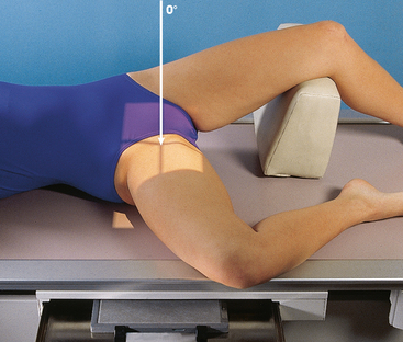
The Lauenstein and Hickey methods are used to show the hip joint and the relationship of the femoral head to the acetabulum. This position is similar to the previously described modified Cleaves method.
• Adjust the patient’s body, and center the affected hip to the midline of the grid.
• Ask the patient to flex the affected knee and draw the thigh up to a position at nearly a right angle to the hip bone.
• Keep the body of the affected femur parallel to the table.
• Extend the opposite limb and support it at hip level and under the knee.
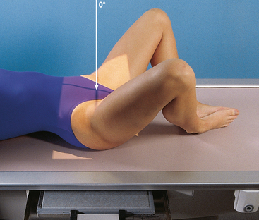
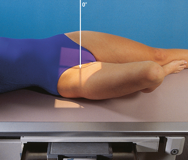
• Rotate the pelvis no more than necessary to accommodate flexion of the thigh and to avoid superimposition of the affected side (Fig. 7-32).
• Perpendicular through the hip joint, which is located midway between ASIS and pubic symphysis for the Lauenstein method (Fig. 7-33) and at a cephalic angle of 20 to 25 degrees for the Hickey method (Fig. 7-34)
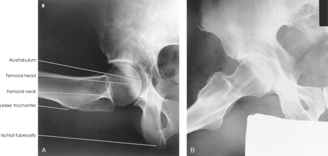
Structures shown: The resulting image shows a lateral projection of the hip including the acetabulum, proximal end of the femur, and relationship of the femoral head to the acetabulum (see Figs. 7-33 and 7-34).
AXIOLATERAL PROJECTION
This projection is often called the cross-table or surgical-lateral projection.
• When examining a patient who is thin or who is lying on a soft bed, elevate the pelvis on a firm pillow or folded sheets sufficiently to center the most prominent point of the greater trochanter to the midline of the IR. The support must not extend beyond the lateral surface of the body; otherwise, it would interfere with the placement of the IR.
• When the pelvis is elevated, support the affected limb at hip level on sandbags or firm pillows.
• Flex the knee and hip of the unaffected side to elevate the thigh in a vertical position.
• Rest the unaffected leg on a suitable support that does not interfere with the central ray. Special support devices are available. Do not rest the foot on the x-ray tube or collimator.
• Adjust the pelvis so that it is not rotated (Figs. 7-35 and 7-36).
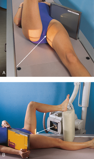
Fig. 7-35 A, Axiolateral hip: Danelius-Miller method, IR supported with sandbags. B, Same projection, patient holding IR. Foot is on a footrest.
• Unless contraindicated, grasp the heel and medially rotate the foot and lower limb of the affected side about 15 or 20 degrees. A sandbag may be used to hold the leg and foot in this position, and a small support can be placed under the knee. The manipulation of patients with unhealed fractures should be performed by a physician.
• Place the IR in the vertical position with its upper border in the crease above the iliac crest.
• Angle the lower border away from the body until the IR is exactly parallel with the long axis of the femoral neck.
• Support the IR in this position with sandbags or a vertical IR holder. These are the preferred methods. Alternatively, the patient may support the IR with the hand.
• Be careful to position the grid so that the lead strips are in the horizontal position.
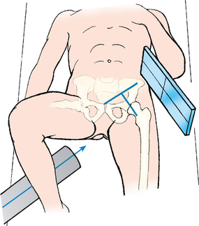
• Perpendicular to the long axis of the femoral neck. The central ray enters at the mid-thigh and passes through the femoral neck about 2½ inches (6.4 cm) below the point of intersection of the localization lines described previously (see Fig. 7-12).
 COMPENSATING FILTER
This projection is improved dramatically and can be performed with one exposure with the use of a specially designed compensating filter (see Fig. 2-9 in Chapter 2).
Structures shown: The resulting image shows the acetabulum, head, neck, and trochanters of the femur (Fig. 7-37).
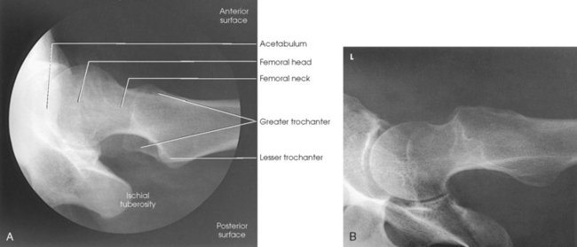
Fig. 7-37 A, Axiolateral hip: Danelius-Miller method. B, Same projection with use of compensating filter. Note excellent detail of acetabular area and femur.
The following should be clearly shown:
Femoral neck without overlap from the greater trochanter
Small amount of the lesser trochanter on the posterior surface of the femur
Small amount of the greater trochanter on the anterior and posterior surfaces of the proximal femur when the femur is properly inverted
Soft tissue shadow of the unaffected thigh not overlapping the hip joint or proximal femur
MODIFIED AXIOLATERAL PROJECTION
CLEMENTS-NAKAYAMA MODIFICATION
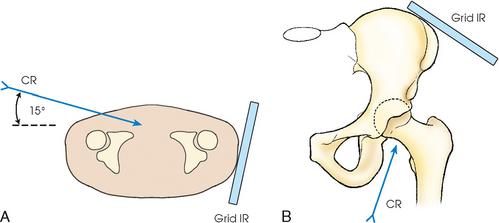
When the patient has bilateral hip fractures, bilateral hip arthroplasty (plastic surgery of the hip joints), or limitation of movement of the unaffected leg, the Danelius-Miller method cannot be used. Clements and Nakayama1 described a modification using a 15-degree posterior angulation of the central ray (Fig. 7-38).
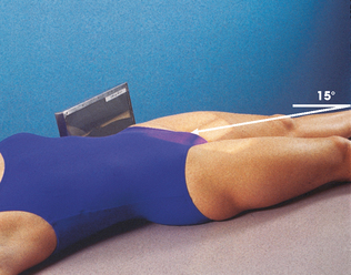
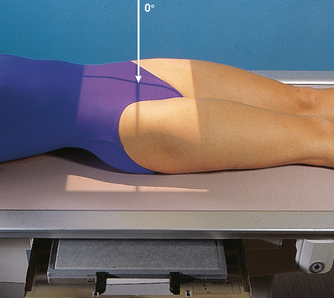
• For this position, do not rotate the lower limb internally. Instead, the limb remains in a neutral or slightly externally rotated position.
• Support a grid IR on the Bucky tray so that its lower margin is below the patient. Position the grid so that the lines run parallel with the floor.
• Adjust the grid parallel to the axis of the femoral neck, and tilt its top back 15 degrees.
• Directed 15 degrees posteriorly and aligned perpendicular to the femoral neck and grid IR (Fig. 7-39)
Structures shown: This leg position shows a lateral hip image because the central ray is angled 15 degrees posterior instead of the toes being medially rotated. The resulting image shows the acetabulum and the proximal femur including the head, neck, and trochanters in lateral profile. The Clements-Nakayama modification (Fig. 7-40) can be compared with the Danelius-Miller approach described previously (Fig. 7-41).
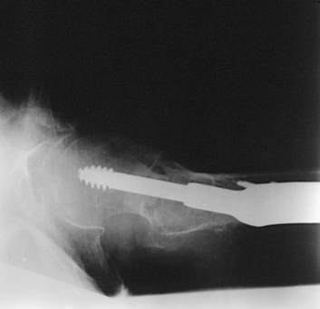
Fig. 7-40 Clements-Nakayama method with 15-degree central ray angulation in same patient as in Fig. 7-41.
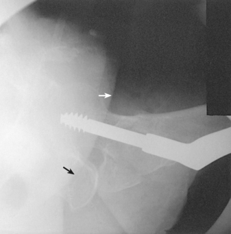
Fig. 7-41 Postoperative Danelius-Miller method used for a patient who was unable to flex unaffected hip. Contralateral thigh (arrows) is obscuring femoral head and acetabular area.
Acetabulum
RAO or LAO position
• Align the body, and center the hip being examined to the midline of the grid.
• Elevate the unaffected side so that the anterior surface of the body forms a 38-degree angle from the table (Fig. 7-42).
• Have the patient support the body on the forearm and flexed knee of the elevated side.
• With the IR in the Bucky tray, adjust the position of the IR so that its midpoint coincides with the central ray.
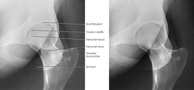
Structures shown: The resulting image shows the fovea capitis and particularly the superoposterior wall of the acetabulum (Fig. 7-43).
AP OBLIQUE PROJECTION
JUDET METHOD1
MODIFIED JUDET METHOD2
RPO or LPO position
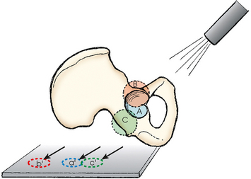
Judet et al.1 described two 45-degree posterior oblique positions that are useful in diagnosing fractures of the acetabulum: the internal oblique position (affected side up) and the external oblique position (affected side down).
Internal oblique
The internal oblique position is for a patient with a suspected fracture of the iliopubic column (anterior) and the posterior rim of the acetabulum.
NOTE: Iliopubic column (anterior)—composed of a short segment of the ilium and the pubis; extends up as far as the anterior spine of the ilium and extends from the symphysis pubis and obturator foramen through acetabulum to ASIS.
• Align the body, and center the hip being examined to the middle of the IR.
• Elevate the affected side so that the anterior surface of the body forms a 45-degree angle from the table (Fig. 7-44, A).
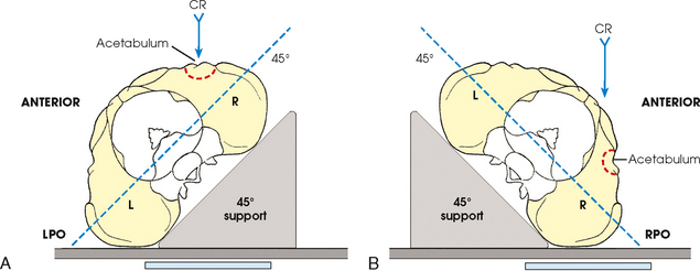
External oblique
The external oblique is for a patient with a suspected fracture of the ilioischial column (posterior) and the anterior rim of the acetabulum.
• Align the body, and center the hip being examined to the middle of the IR.
• Elevate the affected side so that the anterior surface of the body forms a 45-degree angle from the table (Fig. 7-44, B).
Structures shown: The resulting image shows the acetabular rim (Fig. 7-45).
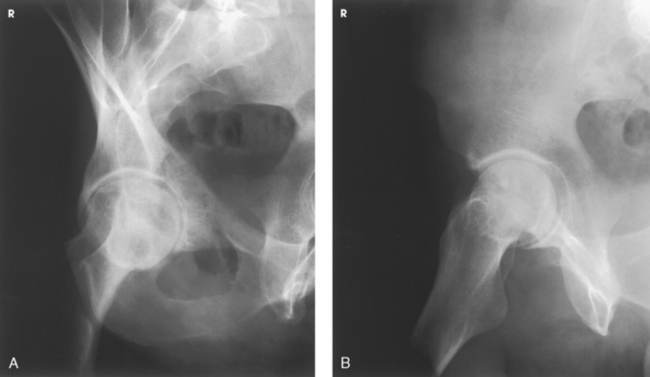
Fig. 7-45 AP oblique projection, Judet method, right hip. A, LPO. B, RPO. (From Long BW, Rafert JA: Orthopedic radiography, Philadelphia, 1995, Saunders.)
NOTE: Ilioischial column (posterior)—composed of the vertical portion of the ischium and the portion of the ilium immediately above the ischium and extends from the obturator foramen through the posterior aspect of the acetabulum.
NOTE: Rafert and Long1 described a modification of the Judet method on trauma patients. The patient is not required to lie on the affected side for the external oblique (Fig. 7-46).
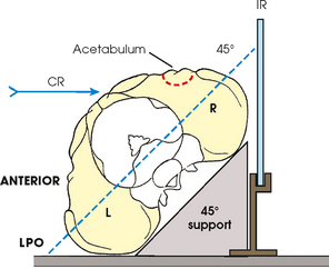
Fig. 7-46 AP oblique projection, modified Judet method for right hip on a trauma patient. External oblique projection is obtained using cross-table central ray (CR) and grid IR. Internal oblique is obtained on a trauma patient in same position using vertical CR (same as Fig. 7-44, A).
RESEARCH: Catherine E. Hearty, MS, RT(R), performed the research and provided this new projection for this edition of the atlas.
Anterior Pelvic Bones
Anterior Pelvic Bones
TAYLOR METHOD1
• Center the midsagittal plane of the patient’s body to the midline of the grid, and adjust the pelvis so that it is not rotated. ASIS should be equidistant from the table (Fig. 7-49).
• Flex the knees slightly with a support underneath if the patient is uncomfortable.
• With the IR in the Bucky tray, adjust the tray’s position so that the midpoint of the IR coincides with the central ray.
Structures shown: The resulting image shows the superior and inferior rami without the foreshortening seen in a PA or AP projection owing to the central ray being more perpendicular to the rami (Figs. 7-50 and 7-51).
SUPEROINFERIOR AXIAL INLET PROJECTION
BRIDGEMAN METHOD1
• Center the midsagittal plane of the patient’s body to the midline of the grid.
• Flex the knees slightly and support them to relieve strain.
• Adjust the pelvis so that ASIS are equidistant from the table.
• With the IR in the Bucky tray, center it at the level of the greater trochanters (Fig. 7-52).
Structures shown: The resulting image shows an axial projection of the pelvic ring, or inlet, in its entirety (Fig. 7-53).
Ilium
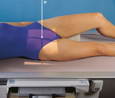
RPO and LPO positions
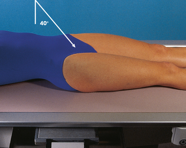
• Center the sagittal plane passing through the hip joint of the affected side to the midline of the grid.
• Elevate the unaffected side approximately 40 degrees to place the broad surface of the wing of the affected ilium parallel with the plane of the IR.
• Support the elevated shoulder, hip, and knee on sandbags.
• Adjust the position of the uppermost limb to place ASIS in the same transverse plane (Fig. 7-54).
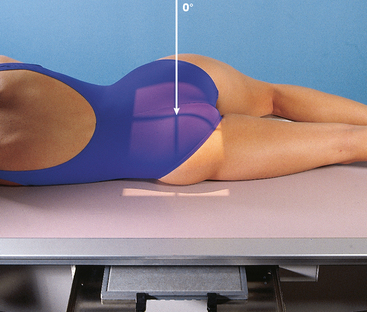
RAO and LAO positions
• Center the sagittal plane passing through the hip joint of the affected side to the midline of the grid.
• Elevate the unaffected side about 40 degrees to place the affected ilium perpendicular to the plane of the IR.
• Have the patient rest on the forearm and flexed knee of the elevated side.
• Adjust the position of the uppermost thigh to place the iliac crests in the same horizontal plane.
• Center the IR at the level of ASIS (Fig. 7-55).
1Bello A: An alternative positioning landmark, Radiol Technol 5:477, 1999.
1Martz CD, Taylor CC: The 45-degree angle roentgenographic study of the pelvis in congenital dislocation of the hip, J Bone Joint Surg Am 36:528, 1954.
1Berkebile RD et al: The gull-wing sign: value of the lateral view of the pelvis in fracture dislocation of the acetabular rim and posterior dislocation of the femoral head, Radiology 84:937, 1965.
1Cleaves EN: Observations on lateral views of the hip, AJR Am J Roentgenol 34:964, 1938.
1Cleaves EN: Observations on lateral views of the hip, AJR Am J Roentgenol 34:964, 1938.
1Andren L, von Rosén S: The diagnosis of dislocation of the hip in newborns and the primary results of immediate treatment, Acta Radiol 49:89, 1958.
2Knake JE, Kuhns LR: A device to aid in positioning for the Andren-von Rosén hip view, Radiology 117:735, 1975.
1Clements RS, Nakayama HK: Radiographic methods in total hip arthroplasty, Radiol Technol 51:589, 1980.
1Judet R et al: Fractures of the acetabulum: classification and surgical approaches for open reduction, J Bone Joint Surg Am 46:1615, 1964.
2Rafert JA, Long BW: Showing acetabular trauma with more clarity, less pain, Radiol Technol 63:93, 1991.
1Judet R et al: Fractures of the acetabulum: classification and surgical approaches for open reduction, J Bone Joint Surg Am 46:1615, 1964.
1Rafert JA, Long BW: Showing acetabular trauma with more clarity, less pain, Radiol Technol 63:93, 1991.
1Taylor R: Modified anteroposterior projection of the anterior bones of the pelvis, Radiog Clin Photog 17:67, 1941.
1Bridgeman CF: Radiography of the hip bone, Med Radiog Photog 28:41, 1952.