Orthotics
Section 1: Hand Splinting: Principles, Practice, and Decision Making
Role of the occupational therapist
Anatomic structures of the hand
Mechanics of the hand and principles of splinting
When to splint and when not to splint
Step two: choosing appropriate material
Step three: choosing the type of traction
Section 2: Suspension Arm Devices and Mobile Arm Supports
After studying this chapter, the student or practitioner will be able to do the following:
1 Identify basic hand anatomy.
2 Describe the difference between single-axis and multiaxis joints and explain how they relate to splinting.
3 Define torque and describe how a splint produces torque.
4 Discuss the relationship of angle of approach to dynamic splinting.
5 Describe the three major purposes and goals of splints and when they should be employed.
6 Demonstrate an understanding of the principles of making a splint pattern.
7 Identify three characteristics of low-temperature thermoplastic material.
8 Discuss two ways in which splints may apply force.
9 Demonstrate how to determine the proper length of a forearm-based splint.
10 List the purposes of suspension arm devices.
11 Describe the limitations of the suspension arm support.
12 List the elements of adjustment for suspension arm devices.
13 Briefly describe the evolution of the traditional mobile arm support (MAS) and name its parts.
14 List the benefits of the MAS for persons with severe upper extremity weakness.
15 List the criteria for use of the MAS and describe how it works.
16 List two special parts of the MAS.
17 Describe the advantages of the JAECO-Rancho Multilink Mobile Arm Support.
According to Mosby’s Medical, Nursing, & Allied Health Dictionary, orthotics is “the design and use of external appliances to support a paralyzed muscle, promote a specific motion, or correct musculoskeletal deformities”; an orthosis is “a force system designed to control, correct, or compensate for a bone deformity, deforming forces, or forces absent from the body … [and] often involves the use of special braces”; and a splint is “an orthopedic device for immobilization, restraint, or support of any part of the body.”2 Splints and suspension arm devices can be considered orthoses. Occupational therapists (OTs) often design and construct splints. An orthotist usually designs and constructs suspension arm devices, and OTs adjust them and train clients to use them. In practice, the term orthosis is used more frequently to refer to suspension arm devices than splints. Hand splinting is the topic of Section 1 of this chapter, and suspension arm devices are described in Section 2.
Section 1 Hand Splinting: Principles, Practice, and Decision Making
 Threaded Case Study
Alexei, Part 1
Alexei is a delightful, witty gentleman of 78 years who resides in a nice retirement complex in the area since the passing of his wife 5 years ago. The complex offers three levels of care: independent apartment living, assisted living, and nursing care. At the time of his injury, Alexei was living in the independent area, had his own self-furnished apartment, took the van transportation provided by the complex once a week for grocery shopping, and took public transportation to his weekly computer class at a nearby senior center. The complex offers some extra services for a fee, and Alexei paid for monthly housekeeping. He does his own laundry, cooking, and light cleaning. He has diabetes and takes care of his own testing and insulin injections. His beloved parakeet recently died, and he was shopping for another. He had trained the parakeet to do several tricks, and it was his pride and joy.
It was outside a pet store that he fell and suffered a comminuted distal radius and ulna fracture of his right dominant wrist. After open reduction and internal fixation (ORIF), he was discharged to the nursing care level of his complex for 2 days, then to the assisted living level. Unless he could quickly become independent with managing his activities of daily living (ADLs) and medical needs, in his case diabetic testing and injections, he would lose his apartment and be transferred to the assisted living level permanently. This level would not allow him a pet.
Alexei was 5 weeks post ORIF when he was referred to hand therapy for beginning active range of motion (ROM) and edema reduction. He was wearing a protective removable splint. Because of maximal edema in his hand, he had only 20% total active motion of his fingers and thumb and was assisted with most self-care and ADLs, was eating with his left, nondominant hand, and was dependent on nursing for his diabetic needs. Alexei’s goal was to regain enough range of motion and dexterity in his right dominant hand to be independent with all ADLs and medical needs so he could return to his apartment, which would allow him to keep his own furniture, get another bird, and set his own schedule.
Although Alexei’s insurance would cover any needed therapy, he was able to attend only once a week because of transportation issues. Because his therapy time would be limited, our focus in OT was to work toward his goals by using dynamic splinting to regain ROM for functional grip and pinch, and to collaborate with the nursing staff at his assisted living residence to help him meet his goal of managing his medical needs. Alexei attended therapy six times over the following 5 weeks. We worked closely by telephone with the nurse in assisted living, who carried out our recommended contrast baths and nightly isotoner glove application to reduce edema. We fabricated a volar-based dynamic flexion splint for metacarpophalangeal (MP) and proximal interphalangeal (PIP) flexion and a dorsal-based finger extension splint, each of which he alternated during the day for approximately 2 to 3 hours. We adjusted his splints each visit for greater ROM and proper 90-degree angle of pull on each finger; he was quick to learn his exercise regimen and followed it religiously. By his third visit, Alexei was independent in all self-care and hygiene tasks using built-up utensil handles and a zipper pull. At this time, we were able to discontinue his extension splint and focus on flexion and dexterity.
At this point, Alexei became assertive with his wish to return to his own apartment and was allowed to move back, with his assurance that soon he would once again be independent in all areas. He partnered with the nurse to work toward independence with medical needs—a difficult task because insulin needles are small and smooth. As his ROM and dexterity improved through dynamic splinting, he was able to test his sugar levels and walk to assisted living to receive insulin as needed. At 14 weeks postop, he was once again independent with his own injections using coban or rubber finger cots for traction on the needle, and was once again shopping for a parakeet.
1. What would have happened to Alexei if therapy had consisted of just the 45-minute ROM and edema reduction sessions once a week, without the addition of the dynamic splint for home use?
2. How critical was the team approach of the client, the therapist, and the nurse in achieving this client’s ultimate goals?
3. What part did ascertaining the client’s main goal during the initial interview play in using limited time and resources to achieve that goal?
4. What would have happened if weekly therapy were conducted without that goal as the primary focus?
A client-centered focus is vital for any type of therapy. The case of Alexei illustrates how splinting was used to achieve a good outcome in a difficult case.
The human hand is the brain’s most important instrument for exploring and mastering the world. We read with our hands if we suffer loss of vision; we communicate with our hands in the absence of speech or hearing. Our hands give us expression and console us. We first explore our hands and explore with our hands as infants. The wonder of the human hand is the precision with which it functions and the extremes of abuse it tolerates. We can and do take our hands for granted as they complete a multitude of functional tasks such as dressing, cooking, or typing, because they seem to function effortlessly—that is, until we experience some level of impairment or dysfunction.
The hand does not function independently of the whole human organism. It is connected to the brain via a complex tangle of nerves and is dependent on precise synaptic connections. The hand does not function independently of the upper extremity (UE); stability and control of the shoulder, elbow, and wrist are needed to position the hand in space. Dysfunction anywhere from the brain to the fingertips may cause impaired function of the hand.
Humans achieve mastery and independence over their environment because of the superiority of the human brain and the dexterity of the hand. Tying a knot, opening a necklace clasp, wielding a hammer, and throwing a ball are abilities unique to the human hand. That we can close a necklace with our vision occluded is testament to the sensibility of the hand. That we can wield a hammer to drive a nail is testament to the integrity of the skin and the strength of the muscles that power the hand. That we can speak volumes with a sweep of our hands or a caressing touch is testament to the aesthetics of the hand. It is a remarkable instrument indeed. As Mary Reilly, one of the profession’s most recognized leaders, stated in her 1961 Slagle lecture, “Man through the use of his hands as they are energized by mind and will, can influence the state of his own health.”
OTs deal with the human being as a whole, not just as a hand, a toe, or a shoulder. With the human hand, even the smallest impairment may affect function. Loss of placement of the hand may mean an inability to achieve a hand-to-mouth pattern, which makes independent feeding impossible. Pain and fear can and do accompany injury, and when independence or livelihood is threatened by hand dysfunction, the outcomes are often dramatic, affecting that person and the family members who rely on him or her. The hand is perhaps most valued only when it ceases to function and we must give it attention.
A splint is one of the most important tools therapists use to minimize or correct impairment and to restore or augment function. Little else so readily calls attention to the hand as a splint. An individual may not receive comments on a new ring or a recent manicure, but put a splint on the hand and all will take notice. The decision to provide or fabricate a splint requires an in-depth understanding of the pathologic condition to be affected and of the many splinting choices available.
Section 1 of this chapter serves as an introduction to the anatomic and biomechanical principles necessary for an understanding of the basic concepts and models of splinting. This section briefly reviews the anatomy of the hand and its relationship to principles of splinting, introduces the biomechanical principles involved in splint design and fabrication, and introduces a splint fabrication process involving pattern making, material choices, types of traction, and techniques of fabrication.
Role of the Occupational Therapist
The education an OT receives in analysis of activity and assessment of human occupation and function leads naturally to the use of splinting as one therapeutic tool in the intervention regimen. OTs most commonly fabricate splints for the hand and UE, but they may be called upon to design and fabricate splints for the lower extremity (LE) and even for the back or spine. The basic principles of splinting apply, regardless of which body part is being splinted.
Involvement of the OT in all phases of splint fabrication is recommended from the initial assessment of need, through the design phase, the fabrication, and the training and follow-up necessary to ensure proper use and fit of the splint. This involvement requires an understanding of the anatomy and biomechanics of the normal, unimpaired hand and of the pathology of the impaired hand. Many excellent texts describe both hand anatomy and biomechanics in extensive detail and should be included in the library of any OT treating the hand. This chapter briefly reviews the anatomy and biomechanics of the hand most pertinent to splinting. The lists of references and suggested readings at the end of this chapter provide several excellent selections for further study.
One reference of note that should be included in every therapist’s library is Clinical Mechanics of the Hand,8 3rd edition, by Paul W. Brand and Anne Hollister. This text is an excellent source for a straightforward explanation of the mechanics of muscles, joints, and skeletal structures and how they contribute to the remarkable dexterity and strength of the hand. Brand and Hollister discuss clinical approaches and how they affect the natural biomechanics of the hand.
Anatomic Structures of the Hand
The hand and wrist are a complex of 27 bones that contribute to the mobility and adaptability of the upper extremity; the 54 bones that make up both hands and wrists account for approximately one fourth of the total bones of the human body. The wrist is a complex that consists of the distal ulna and radius and the eight carpal bones arranged in two rows. The carpal bones form the concave transverse arch and, with the configuration of the distal radius, contribute substantially to the conformability of the hand.28 The distal ulna does not articulate with any carpal bone, and its contribution to wrist stability is made through the attachments of the ulnar collateral ligament, which places a check on radial deviation (Figure 30-1).
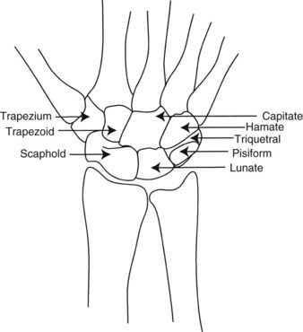
The wrist complex allows a greater arc of motion than any other joint complex except the ankle. This mobility is the result of a unique skeletal configuration and an involved ligamentous system. All motion at the wrist is component motion that occurs in more than one anatomic plane; no pure or isolated motions occur. This concept is key in any treatment directed at the wrist. Extension occurs with a degree of radial deviation and supination. Wrist flexion includes ulnar deviation and pronation. The wrist is contiguous and continuous with the hand. The distal carpal row (the trapezium, trapezoid, capitate, and hamate) articulates firmly with the metacarpals. Motion is produced across these articulations by muscles that cross the carpals and attach to the metacarpals. The proximal carpal row (the scaphoid, lunate, and triquetrum) articulates distally with the distal carpal row, and proximally with the radius and the triangular cartilage. Gliding motions occur between the carpal rows during flexion, extension, and deviation, and excessive motion is checked by the carpal ligaments.
Placement of the hand for functional tasks is reliant on the stability, mobility, and precision of placement permitted by the wrist complex. Any mechanism of injury or disease that alters this complex system, such as rheumatoid arthritis, translates into some level of dysfunction. Even the simplest splint that crosses the wrist will alter in some way the functional abilities of the hand.
 OT Practice Note
Splint designs that attempt to augment or substitute for wrist motion are likely to limit component motions or are too complex to fabricate or wear.
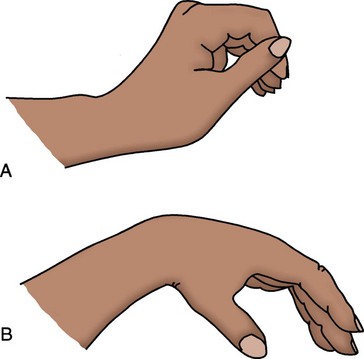
Wrist Tenodesis: Tenodesis is the reciprocal motion of the wrist and fingers that occurs during active or passive wrist flexion and extension. Tenodesis is the action of wrist extension producing finger flexion, and wrist flexion producing finger extension. It is caused by lack of change in length of the long finger muscles during wrist flexion or extension (Figure 30-2). The extrinsic finger muscle tendon units have a fixed resting length; because they cross multiple joints before inserting onto the phalanges, they can affect the position of several joints with no contraction or length change required of the muscles. This concept is crucial for understanding how passive positioning of the wrist affects the resting position of the digits. In the nerve-injured hand, tenodesis is often harnessed by splints to provide function. The client with spinal cord injury with sparing of a wrist extensor (C6 or C7 functional level) gains considerable function from a tenodesis, or wrist-driven flexor hinge hand splint. In a dynamic splint, such as a tenodesis splint, the effect that tenodesis has on tendon length will dictate in part the wrist position that will optimize forces directed at the digits.
Metacarpal Joints
The metacarpals articulate with the carpal bones proximally and with the phalanges distally. The first metacarpal, the thumb, articulates with the saddle-shaped trapezium and is considered separately. The second metacarpal fits into the central ridge of the trapezoid, and the third articulates firmly with the facets of the capitate. These articulations form the immobile central segment of the hand around which the other metacarpals rotate. The fourth and fifth metacarpals articulate with the concave distal surface of the hamate. The shorter length of the ulnar two metacarpals and their greater mobility form the flexible arches of the hand; this allows it to conform and fold around objects of various shapes.
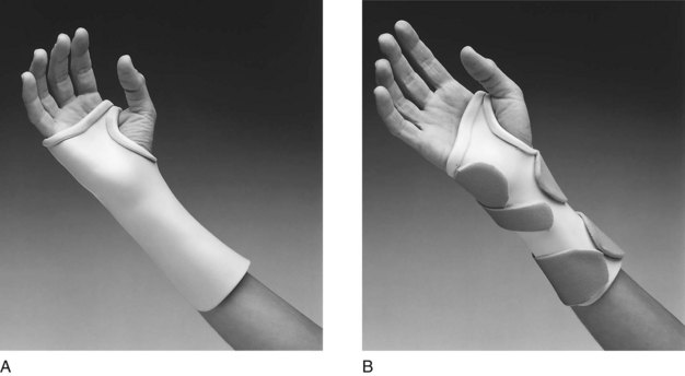
The distal transverse arch of the hand lies obliquely across the metacarpal heads. This obliquity is critical to the ability of the hand to adapt its shape to objects. The hand does not form a cylinder as it closes but instead assumes the position of a cone. In making a fist, the ulnar two digits of the hand contact the palm first, and the radial two digits follow. This cascade of the fingers is a direct result of the oblique angle formed at the metacarpal heads (sloping angle, not parallel to the wrist). This concept is most important in splinting in determining the distal trim lines for a wrist support when full metacarpophalangeal (MP) flexion is desired. The splint in Figure 30-3, A, is improperly trimmed distal to the MP creases. Distal trim lines should be established proximal to the MP creases, as in Figure 30-3, B.
Metacarpophalangeal Joints
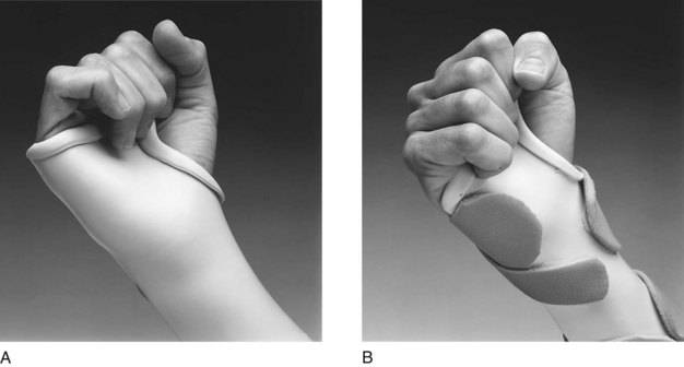
The distal heads of the metacarpals articulate with the proximal phalanges to form the MP joints. Active motion is possible along an axis of flexion and extension, and along an axis of abduction and adduction. In addition, a small degree of rotation is present at the MP joints. These axes of motion allow for expansion or spreading of the hand and contribute to the ability of the hand to conform to different shapes and sizes of objects. An attempt to hold a softball without abduction of the fingers shows the importance of this motion. A splint with trim lines along the ulnar border of the hand that extend too far distally limits flexion and abduction of the fourth and fifth digits. As a result, the hand will have a limited ability to grasp large objects, and function will be restricted (Figure 30-4, A). Distal trim lines that fall proximal to the MP creases will allow for full MP flexion (Figure 30-4, B).
Thumb
The base of the first metacarpal articulates with the trapezium to form a highly mobile joint that often is compared with the shape of a saddle. The base of the first metacarpal is concave in the anteroposterior plane and convex in the lateral plane. This surface is met by reciprocal surfaces on the trapezium. This configuration allows for a wide arc of motion, with the thumb able to rotate not only for pad-to-pad opposition, but also for full extension and abduction to move away from the palm.28 Both motions are important to function, that is, a thumb posted in permanent opposition may make grasp possible but release of objects impossible. This concept is crucial to an understanding of splints that augment the tenodesis action of the hand by posting the thumb in opposition to the index and long fingers. With such splints, the therapist must carefully consider the degree of abduction and opposition in which the thumb is posted, to maximize both grasp and release.
Interphalangeal Joints
The proximal interphalangeal (PIP) and distal interphalangeal (DIP) joints are true hinge joints, with motion in only one plane. This limitation of motion ensures greater stability in these joints, which contributes to their ability to resist palmar and lateral stresses, and so imparts strength and precision to functional tasks.
Forearm Rotation
Close consideration of forearm rotation (i.e., supination and pronation) is necessary because of the importance of these motions to function and to the fitting of splints. Forearm rotation occurs at the elbow and at the distal forearm, with axes of rotation through the center of the radial head and capitulum and along a line extending through the base of the ulnar styloid (Figure 30-5). During pronation, the ulnar styloid moves laterally, as the radial styloid travels medially. During supination, the opposite occurs, with the ulnar styloid moving medially. This movement results in displacement of the styloids, which in turn alters the architecture of the forearm in supination as compared with pronation.
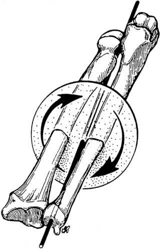
FIGURE 30-5 The axis of motion for supination and pronation extends the length of the forearm and is centered through the radial head and capitulum and the distal ulnar styloid. (From Colello-Abraham K: Rehabilitation of the hand, ed 3, St Louis, 1990, Mosby.)
The way in which this change in dimensions affects splint trim lines is shown in Figure 30-6. Lines drawn at midline along the supinated forearm shift dramatically upon pronation. Splints are generally used for function with the forearm in pronation, but they are easier to fabricate with the forearm in supination. Important to note is that if the forearm is not pronated before the splint material is set, the trim lines will be high on the radial border and low on the ulnar border.
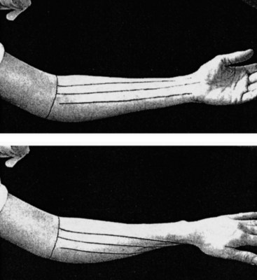
FIGURE 30-6 The shape of the forearm is altered as it moves from supination to pronation. Forearm-based splints must be repositioned to accommodate this if the forearm is rotated during the fabrication process. (From Wilton JC: Hand splinting, principles of design and fabrication, Philadelphia, Pa, 1997, WB Saunders.)
One final active demonstration highlights the importance of forearm position for hand function. Place a coin of any size on a tabletop, and while holding the forearm in neutral (thumb straight up), attempt to pick up the coin. It becomes rapidly apparent that the ability to position the hand for function relies in great part on the more proximal joints of the forearm.
Ligaments of Wrist and Hand
The ligamentous structures of the hand act as checkreins for the hand and wrist; this limits extremes of motion and provides stability. The complex motions of the wrist depend in large part on the ligaments that restrain them, rather than on the contact surfaces between the carpals and metacarpals. Three groups of ligaments are discussed briefly to highlight their contribution to wrist stability and mobility.
The palmar ligaments include the radioscaphocapitate ligament, which contributes support to the scaphoid; the radiolunate ligament, which supports the lunate; and the radioscapholunate ligament, which connects the scapholunate articulation with the palmar surface of the distal radius. The stability and mobility of the thumb and radial carpus depend on the integrity of these ligaments. Disruption of the ligaments results in instability and pain at the wrist and in significant dysfunction of the thumb. Splinting is frequently the treatment of choice to supply stability for pain reduction.
The radial and ulnar collateral ligaments provide dorsal stability. These capsular ligaments, along with the radiocarpal and dorsal carpal ligaments, provide carpal stability and permit ROM. Disruption of any of these ligaments may result in pain, loss of strength, and functional impairment.
The triangular fibrocartilage complex (TFCC) includes the ligaments and the cartilaginous structures that suspend the distal radius from the distal ulna and the proximal carpus. Tears or strains in this complex are evidenced by pain and weakness with resultant loss of function in resistive tasks. The advent of new imaging techniques has made the diagnosis of TFCC tears more common; splinting is often ordered for support and pain relief.
Metacarpophalangeal Joints: Soft tissue structures that surround the MP joints include the joint capsule, the collateral ligaments, and an anterior fibrocartilage or volar plate. The capsule covers the head of the metacarpal and is reinforced by the collateral ligaments. The collateral ligaments are configured to allow side-to-side motion when the MP is in extension, and to tighten as the MP is flexed. The volar plate is attached to the base of the proximal phalanx and is loosely attached to the base of the neck of the metacarpal through the joint capsule. This configuration allows for sliding of the plate proximally during MP flexion. The plate returns to its lengthened state with the MP in extension and acts as a checkrein for volar displacement of the MP joint when it is extended.
When MPs are immobilized in extension, a strong tendency exists for secondary shortening of the lax collateral ligaments, in addition to contraction and adherence of the volar plate, which results in limited MP flexion and loss of functional grasp patterns. The commonly accepted resting position splint, which places the wrist in 25 degrees to 35 degrees of extension, the MP joints at 60 degrees to 70 degrees of flexion, and the PIP and DIP at 10 degrees to 35 degrees of flexion, is designed to prevent shortening and to maintain the joints in midrange for optimal function. An important consideration is to ensure that the mobile fourth and fifth digits are positioned in the splint to accommodate their additional degree of mobility by allowing somewhat greater flexion at their MP joints (Figure 30-7).
Proximal Interphalangeal Joints: The PIP joint capsule and ligaments provide stability and allow mobility in one plane only. Collateral ligaments on each side of the joint run in a dorsal-to-palmar direction, inserting into the fibrocartilage plate of the PIP. These ligaments and the plate are lax with the PIP joint in flexion and taut with it in extension. The seemingly simple joint is made more complex by inclusion of the extensor mechanism passing through the capsule dorsally and contributing slips to the system of ligaments affecting this joint. The potential for disruption of the extensor mechanism is high. Many of the most commonly fabricated finger splints are used to correct PIP boutonniere (Figure 30-8, A) and swan-neck (Figure 30-8, B) deformities.
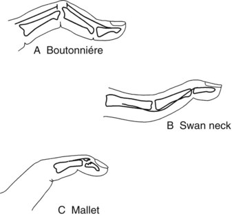
FIGURE 30-8 A, Boutonniere deformity, or joint change, characterized by proximal interphalangeal joint flexion and distal interphalangeal joint hyperextension. B, Swan-neck deformity, or joint change, with proximal interphalangeal joint hyperextension and distal interphalangeal joint flexion. C, Mallet finger with distal interphalangeal joint flexion and loss of active extension.
Distal Interphalangeal Joints: The DIP joint capsule and ligaments are similar to the PIP joint but have less structural strength to the terminal insertions of the palmar plate and collateral ligaments. As the structures become smaller, they lose integrity and strength. One of the most frequent injuries to the digits is disruption of the terminal end of the extensor tendon, which results in a mallet or “baseball” finger (Figure 30-8, C).
Muscles and Tendons of Forearm, Wrist, and Hand
Balance in the hand must be considered when the hand is assessed for a splint. Two groups of muscles act on the wrist and hand: (1) the extrinsic muscles that arise from the elbow and the proximal half of the midforearm, and (2) the intrinsic muscles with origins and insertions entirely in the hand. The extrinsic muscles include both a flexor and an extensor group acting on the wrist and on the digits. The intrinsics include the lumbricals, the dorsal and palmar interossei, and the thenar and hypothenar groups. Smooth, coordinated motions of the hand in functional activities depend on a well-integrated balance between and within these two muscle groups. Many of the contractures that OTs attempt to correct with splinting are caused by neurologic dysfunction (central or peripheral), which results in imbalance of muscle tone or innervation.
Nerve Supply
A discussion of the nerve supply to the hand should include mention of the continuity of the brachial plexus from its origins in the spinal cord to its terminal innervations in the hand. Injuries or compressions that occur anywhere along this continuum may result in motor or sensory dysfunction. When splinting the UE, the therapist must give attention to the pathways of the nerves that supply the UE and to potential sites for nerve entrapment. In the fabrication of splints, care must be taken to avoid applying pressure over sites where the nerves are superficial and prone to compression. These sites include the ulnar nerve at the elbow in the cubital tunnel and in Guyon’s canal at the ulnar border of the wrist, the radial nerve at the elbow and in the thenar snuffbox, and the digital nerves along the medial and lateral borders of the digits (Figure 30-9).
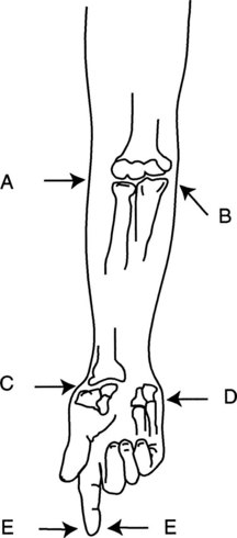
FIGURE 30-9 Potential sites for nerve compression from improperly fitted splints. A, Radial nerve. B, Ulnar nerve. C, Radial digital nerve in anatomic snuffbox. D, Ulnar nerve in Guyon’s canal. E, Digital nerves.
Three peripheral nerves supply motor and sensory function to the hand (Figure 30-10). The radial nerve is the primary motor supplier to the extensor and supinator muscles. The sensory fibers of the radial nerve supply the dorsum and the radial border of the hand. The median nerve provides motor supply to the flexor-pronator group, which includes most of the long flexors and the muscles of the thenar eminence. The sensory distribution of the median nerve is functionally the most important because it includes the palmar surface of the thumb, index, and long fingers and the radial half of the ring finger. The ulnar nerve supplies most of the intrinsic muscles, the hypothenar muscles, the ulnarmost profundi, and the adductor pollicis brevis. The sensory supply of the ulnar nerve includes the palmar surface of the ulnar half of the ring finger, the little finger, and the ulnar half of the palm.
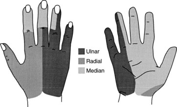
FIGURE 30-10 Sensory distribution in hand. Median nerve distribution includes most of the prehensile surface of the palm.
Nerve dysfunction presents a challenge to the splint maker. Muscle imbalance leads to dysfunctional posturing of the hand and muscle atrophy that reduces the natural padding of the hand. Abrasions or ulcerations may occur in persons who do not remove their splints, because they do not feel pain caused by shearing forces or pressure areas inside the splint. Finally, skin with marked sensory impairment lacks natural oils and perspiration; this leads to dry skin that abrades easily. These factors must be assessed and considered carefully when splints are being fitted on persons with sensory impairment.
Splinting the neurologically impaired hand is directed at preventing joint and soft tissue contractures and restoring functional positioning. Splinting cannot restore sensibility, and care must be taken to prevent damage to sensory-impaired skin and to limit further reduction of sensory feedback by covering sensate surfaces (those surfaces that have sensation) and consequently reducing functional use of the hand in ADLs.
Little consensus has been reached on whether or not splinting the neurologically impaired hand is best practice and should or should not be done, and for what long-term goals. An excellent summary of this debate is provided by Lohman and Aragon in “Introduction to Splinting: A Clinical Reasoning and Problem-Solving Approach” (Chapter 14).10
Blood Supply
Blood supply to the hand is contributed by the radial and ulnar arteries. The ulnar artery lies just lateral to the flexor carpi ulnaris tendon, where it divides into a large branch that forms the superficial arterial arch and a small branch that forms the lesser part of the deep palmar arch. The ulnar artery is vulnerable to trauma where it passes between the pisiform and the hamate (Guyon’s canal). The radial artery divides at the proximal wrist crease into a small, superficial branch and a larger, deep radial branch. The superficial arterial arch further divides into common digital branches and then into proper digital branches.
Venous drainage of the hand is accomplished by two sets of veins: a superficial and a deep group. Therapists are more likely to be concerned with the superficial venous system because it lies superficially in the dorsum of the hand. Disruption of this superficial system may result in extensive fluid edema in the dorsum of the hand, which requires the therapist’s intervention. Care must be taken not to strap splints too tightly over the dorsum of the hand; this traps fluids from draining.
Skin
The mobility of the hand is directly related to the type and condition of the skin. Anyone who has put on a ring that is slightly too small, only to be unable to remove it, has experienced the redundancy of the skin on the dorsum of the hand. The skin on the dorsum of the hand is loosely anchored to underlying structures and moves easily to allow flexion and extension of the digits. The ring “problem” occurs because of a greater degree of elasticity in the dorsal skin when it is pulled distally, as opposed to when it is pulled proximally. This fact should be considered when the use of finger splints is contemplated.
The palmar skin, by contrast, is thicker and relatively inelastic. It is firmly connected to the underlying palmar aponeurosis for stability and protection during prehension activities. Furthermore, the underlying fascia of the palmar skin is thicker and protects the nerve endings, while it acts to supply adequate moisture and oils to the skin surface.
Superficial Anatomy and Landmarks
When fabricating a splint, therapists must consider where to apply force without causing further trauma. Despite its deftness and power, the hand’s lack of protective fascia means that it tolerates external pressures poorly and shearing stresses not at all. The prominent ulnar styloid, the distal radial styloid, and the thumb carpometacarpal joint are common sites for pressure. A truism that will always hold in splinting is that padding adds pressure. The softest padding added to a too-tight splint will only add more pressure. Pressure is relieved by the creation of a relief in the splint or by application of padding and material molded over the pad to make it an integral part of the splint (Figure 30-11). Added padding to relieve pressure after the splint is formed should be avoided.
Prehension and Grasp Patterns
The ability of the human hand to assume myriad functional positions and to apply only the precise amount of pressure necessary to hold an object is a result of the mobility and stability supplied by the skeleton, the power of the muscles, and the remarkable degree of sensory feedback received from the nerves. This sensory feedback is used to assess the size, shape, texture, and weight of an object. The brain then determines which type of prehension to use to complete a functional task while using this object. The feedback used in grasping and lifting an object is dependent both on the brain’s interpreting correctly what is seen and on the hand’s responding appropriately. Once an object is in the hand, further adaptation in prehension will occur if the initial visual assessment was faulty.
Splints can maximize functional prehension. In achieving this goal, the therapist must be aware of what a splint can and cannot do: a splint can stabilize an unstable part, position a thumb in opposition, and even assist or substitute for lost motion. A splint with added dynamic components can even gradually revise tissue along its lines of pull by applying slow gentle stretch to gain increased functional range of motion. However, the splint maker must be aware that a splint may negatively limit mobility at uninvolved joints, reduce sensory feedback, add bulk to the hand, and transfer stresses to unsplinted joints proximal or distal to the part being splinted.
The prehension patterns the hand is able to achieve are as exhaustive as the objects that are available to grasp or pinch. Several authors have contributed to classifications of normal prehension, and the presentation by Flatt12 is recommended for further study of the subject. It is possible to reduce the many patterns to two basic classifications—prehension and grasp—from which other patterns may be derived. Prehension is defined as “a position of the hand that allows finger and thumb contact and facilitates manipulation of objects.” Grasp is defined as “a position of the hand that facilitates contact of an object against the palm and the palmar surface of partially flexed digits.”
The thumb is involved in all but one type of grip, that of hook grasp. Carpometacarpal and MP rotation is crucial to prehension and cannot be overstressed in terms of its importance in splinting to achieve function. This rotation allows for full contact of the thumb in pad-to-pad prehension; this motion is used in a normally active person hundreds of times daily in performance of all areas of occupation, including ADLs, instrumental activities of daily living (IADLs), work, leisure, and social participation.
Lateral Prehension
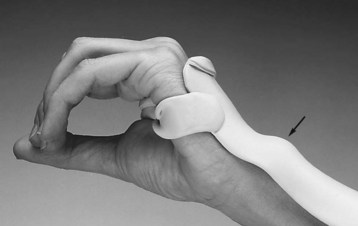
In lateral prehension, the pad of the thumb is positioned to contact the radial side of the middle or distal phalanx of the index finger (Figure 30-12, A). Most commonly, this pattern of prehension is used in holding a pen or eating utensil, and in holding and turning a key. The short or long opponens splint is used to stabilize the thumb to achieve this prehension pattern.
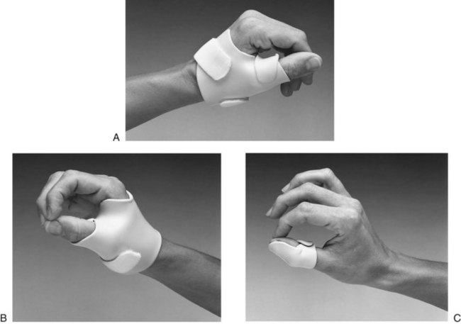
FIGURE 30-12 A, Lateral prehension or key pinch in short opponens splint that positions thumb in lateral opposition to index finger. B, Palmar prehension or three-jaw chuck pinch in short opponens that positions thumb in opposition to index and long fingers. C, Tip prehension with thumb and index finger in interphalangeal blocker that secures interphalangeal joint in slight flexion to assist tip prehension.
Palmar Prehension
Palmar prehension is also called “three-jaw chuck pinch.” The thumb is positioned in opposition to the index and long fingers (Figure 30-12, B). The important component of motion in this pattern is thumb rotation, which allows for pad-to-pad opposition. This prehension pattern is used in lifting objects from a flat surface, in holding small objects, and in tying a shoe or bow. The short and long opponens splints may be fabricated to position the thumb in palmar prehension.
Tip Prehension
In tip prehension, the IP joint of the thumb and the DIP and PIP joints of the finger are flexed to facilitate tip-to-tip prehension (Figure 30-12, C). These motions are necessary for picking up a pin or a coin. It is difficult to substitute for tip prehension because it is rarely a static holding posture. Once a pin is in the hand, tip prehension will convert to palmar prehension to provide more skin surface area to retain a small object. A thumb IP hyperextension block is useful in limiting IP hyperextension and in facilitating the IP flexion required for tip prehension. In the case of Alexei, maximal edema and stiffness prevented him from achieving the tip or palmar prehension needed for his diabetes management, which included manipulation of small objects.
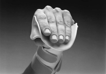
Cylindrical Grasp
Cylindrical grasp, the most common static grasp pattern, is used to stabilize objects against the palm and the fingers, with the thumb acting as an opposing force (Figure 30-13, A). This pattern is assumed for grasping a hammer, a pot handle, a drinking glass, or the handhold on a walker or crutch. Static splinting offers little to restore this grasp directly, although positioning the wrist in extension offers greater stability to the hand as it assumes this grasp pattern. However, a dynamic outrigger component can be added to a volar splint to gently gain increased MP and PIP flexion to enhance cylindrical grasping ability, as was found to be successful for Alexei. A dorsal wrist stabilizer alone offers stability while minimizing palm coverage.
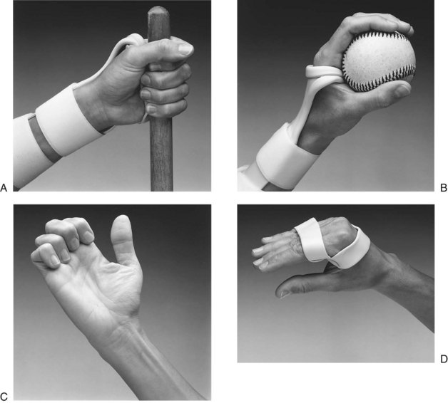
FIGURE 30-13 A, Cylindrical grasp in dorsal splint that stabilizes wrist to increase grip force and minimizes palm covering. B, Spherical grasp in dorsal splint. Splint stabilizes wrist to increase grip force and permits metacarpal mobility required for spherical grasp. C, Hook grasp does not involve thumb. Grasp pattern is seen in median and ulnar neuropathy; splinting is aimed at correcting rather than augmenting grasp. D, Figure-eight splint substitutes for loss of intrinsic function with median and ulnar neuropathy.
Spherical Grasp
Also called ball grasp, this pattern is assumed for holding a round object, such as a ball or an apple. It differs from cylindrical grasp primarily in positioning of the fourth and fifth digits. In cylindrical grasp, the two ulnar metacarpals are held in greater flexion. In spherical grasp, the two ulnar digits are supported in greater extension to allow a more open hand posture (Figure 30-13, B). In splinting, to facilitate or support this pattern of grasp, the wrist-stabilizing splint must be trimmed proximal to the distal palmar crease and contoured to allow for obliquity at the fourth and fifth metacarpal heads.
Hook Grasp
Hook grasp is the only prehension pattern that does not include the thumb to supply opposition. The MPs are held in extension, and the DIP and PIP joints are held in flexion (Figure 30-13, C). This is the attitude the hand assumes when holding the handle of a shopping bag, a pail, or a briefcase. In the nerve-injured hand, splinting is directed more commonly at correcting this posture by flexing the MPs than at facilitating it.
Intrinsic Plus Grasp
Intrinsic plus grasp is characterized by positioning of all MPs of the fingers in flexion, the DIP and PIP joints in full extension, and the thumb in opposition to the third and fourth fingers (Figure 30-13, D). This pattern is used in grasping and holding large, flat objects such as books or plates. Intrinsic plus grasp is often lost in the presence of median or ulnar nerve dysfunction, and a figure-eight or dynamic MP flexion splint is used for substitution.
Mechanics of the Hand and Principles of Splinting
McCollough and Sarrafian stated that the three basic motor functions of the upper limb are “prehension and release, transfer of objects in space, and manipulation of objects within the grasp.”20 These functions depend on the structural integrity of the skeleton, the muscles that provide power, and the feedback to which the brain responds when enabling the limb to meet functional demands. The task of restoring any one of these basic functions through the application of a splint is complex and relies on an understanding of the biomechanics of the hand and the mechanics involved in splinting. It is beyond the scope of this chapter to present this topic in depth. Presented here is an introduction to those tenets of clinical mechanics deemed necessary for the beginning splint maker.
Mechanics deals with the application of force, and biomechanics may be viewed as the body’s response to those forces. In the hand, the force required to produce motion is supplied by muscles. The force then is transmitted by the tendons to the bones and joints, with control supplied by the skin and pulp of the fingers and palm.11 How the application of a splint affects the transmission of force to produce motion depends on the relationship between the axis of rotation of joints and anatomic planes and the forces imposed on the hand.
Axis of Motion
Hollister and Giurintano14 define axis of motion as “a stable line that does not move when the bones of a joint move in relation to each other” (Figure 30-14). This stable line is illustrated by Figure 30-14, B, which shows a tire perfectly balanced around its axis of motion. When a tire is perfectly balanced, it does not wobble; it has pure motion around a single point.
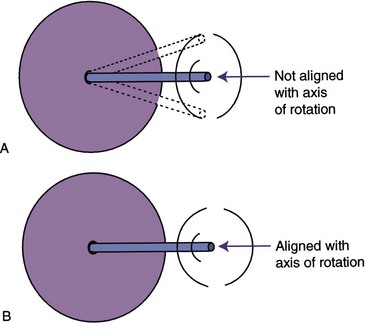
FIGURE 30-14 A, If a tire is not balanced around its axis, it wobbles. If a splint hinge is not aligned with the joint axis, wobble is seen as binding of the joint. B, Proper alignment of a tire or of a hinge with an anatomic joint results in smooth, unimpeded motion.
In a single-axis joint, motion occurs in only one plane. The PIP joint is an example of a single-axis joint in alignment with an anatomic plane. It moves only in the plane of flexion and extension.
Joints that have more than one axis of motion may move in more than one plane at a time. For example, the wrist complex has two axes of motion: flexion-extension and radial-ulnar deviation. A joint with multiple axes has conjoint motions that occur in addition to the primary motions described by the joint. Wrist flexion occurs with a moment of ulnar deviation and with a small degree of pronation. Wrist extension occurs with radial deviation and slight supination. These conjunct motions are what make circumduction of the wrist possible. They are also what make splinting the wrist with hinged joints a challenge.
A splint with a movable hinge or coil has a single axis. When used to splint a single-axis joint such as a PIP joint, a hinge can and should be properly aligned to avoid binding that will limit motion. If a single-axis hinge or coil is used to reproduce motion in a multiaxis joint, some binding or friction will always occur, no matter how well aligned, because the hinge or coil does not allow for, or reproduce, the conjunct motions available in the unsplinted joint.
Force
It is crucial to understand basic principles of force and apply them correctly in splinting. An understanding of the forces applied by levers and the stresses that occur between opposing surfaces can help to explain what happens as forces are applied within the body by muscles and externally by splints.
Definitions: Use of the term force, as it relates to splinting, describes the effects that materials and dynamic components have on bone and tissue. Force is a measure of stress, friction, or torque. Stress is resistance to any force that strains or deforms tissue. Shear stress occurs when force is applied to tissues at an angle or in opposing directions. Pinching skin between the surface of a splint and the underlying bony structures causes shear stress.
Friction occurs when one surface impedes or prevents gliding of a surface on another. Friction is produced in the stiff or contracted joint when soft tissue restriction prevents gliding of the bones. Splints may contribute to friction if they are misaligned in relation to a joint axis. For example, a hinged splint that is not properly aligned with the axis of rotation will limit motion by producing friction as the joint attempts to move.
Torque is a measure of the force that results in rotation of a lever around an axis. The torque created when a lever rotates depends on the force used and the length of the lever employed. In the body, muscles are the levers that create torque when they act to move a joint. Externally, splints may act as levers to apply the force necessary to move a bone around its axis. The measure of torque is given by the following formula:

Internally, the length of the lever arm is measured as the perpendicular distance from the axis of the joint to the tendon. Externally, the length of the lever arm is measured as the estimated distance from the joint axis to the attachment of force. In splinting, the attachment point of the force is usually a soft or molded cuff. If the splint includes an outrigger with a finger cuff, as shown in Figure 30-15, the lever arm is the distance from the axis of the joint to the finger cuff, as indicated in line M.
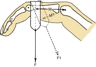
FIGURE 30-15 Tension F on the phalanx has a moment arm of M acting on the joint. Tension F1 has a smaller moment arm, M1 (with less resulting torque), when the angle of approach is not 90 degrees. (From Brand PW, Hollister A: Clinical mechanics of the hand, ed 2, St Louis, 1993, Mosby.)
Figure 30-15 demonstrates that the angle of approach of the force to the finger also affects the length of the lever arm and ultimately the torque applied. The angle of approach is the angle that the line of traction makes as it meets the part being splinted. When the angle of approach is at a right angle (90 degrees) to the long axis of the phalanx, the lever arm is M. When the cuff is at less than 90 degrees to the long axis of the phalanx, the lever arm is shortened to M1. This shorter lever arm will produce less torque and therefore less rotation unless greater force is applied.
Given an equal amount of resistance or load, a 2-foot lever will require half as much force to create motion around an axis as will a 1-foot lever. The important principle for splint makers is that as the distance between the attachment of the cuff or strap and the joint axis increases, less force is required to achieve motion.
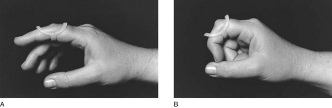
Translational Forces: In addition to the angle of approach affecting the length of the lever arm, an approach of less than or greater than 90 degrees results in translational forces. The outrigger splint in Figure 30-16, A, shows a 90-degree angle of approach between the nylon line and the phalanx, demonstrating the correct angle of pull.

FIGURE 30-16 A, Angle of approach is 90 degrees to middle phalanx, ensuring that force pulling the proximal interphalangeal joint into extension is not causing distraction or compression. B, Angle of approach less than 90 degrees to middle phalanx causes joint compression. C, Angle of approach greater than 90 degrees distracts joint.
When force is applied at any angle other than 90 degrees, translational forces are created. This alteration of the angle of approach translates some of the rotational force away from producing joint extension and directs the force into joint compression or joint distraction (Figure 30-16, B and C). The greater the deviation from 90 degrees, the greater is the translational force. Depending on the type of splint and the condition of the joint, joint compression or distraction may lead to mere discomfort or to actual joint damage. Translational force is also undesirable because it undermines the effectiveness of the splint by shortening the lever arm.8
The challenge in splinting with an outrigger is to position the splint so that a 90-degree angle of approach exists. In the outrigger in Figure 30-17, as long as the finger does not move, the 90-degree angle will remain. As soon as the finger moves, however, the 90-degree angle changes. Because few outriggers allow for this automatic readjustment in position, the outrigger must be adjusted as the contracture lessens to maintain the 90-degree angle of approach.
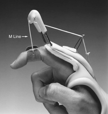
FIGURE 30-17 As dynamic traction acts on range of motion at the proximal interphalangeal joint, splint must be adjusted to maintain 90-degree angle of approach.
Alexei required weekly adjustments of his flexion outrigger to maintain the 90-degree angle of approach as his MP and PIP flexion increased. As his finger flexibility and functional hand motion improved, he was able to lessen time spent in the splint.
Splint Classifications
Splints may be described in various ways. Terminology varies, and it is useful to understand some of the ways that splints may be described. For purposes of clarity, splint classifications are described here according to type, purpose, and design.
One reference to be considered when classification is discussed is the Splint Classification System (SCS),1 as published by The American Society of Hand Therapists (ASHT). The SCS describes splint nomenclature based on the functional requirement of a splint, as well as on the anatomy affected. This nomenclature is quite inclusive of the broad variety of UE splints fabricated by occupational therapists and is suggested for study. However, the widely used terms static, serial static, dynamic, and static progressive are not included in the SCS. These splint choices are noted under “Common Names.” An excellent summary of the Splint Classification System can be found in Jacobs and Austin’s “Splinting the Hand and Upper Extremity, Principles and Process” (Chapter 1).15
Splints Classified by Type
Dynamic splints include one or more resilient components (elastics, rubber bands, or springs) that produce motion. The force applied from the resilient component is constant even when tissues have reached end range. Dynamic splints are designed to increase passive motion, to augment active motion by assisting a joint through its range, or to substitute for lost motion. Dynamic splints generally include a static base on which movable, resilient components can be attached (Figure 30-18). A common use of dynamic splinting is to gain greater finger range of motion by adding dynamic MP extension and/or MP flexion components to a splint. Figure 30-18 shows the type of dynamic splint fabricated for Alexei to gain finger extension. Figure 30-19 shows the type of dynamic splint fabricated for Alexei to gain finger flexion.
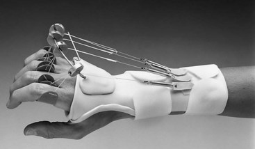
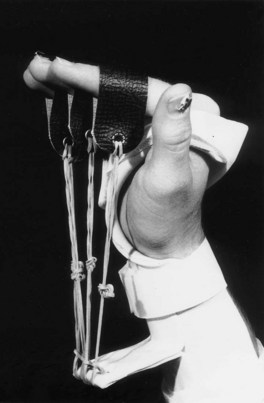
FIGURE 30-19 Dynamic splint for finger flexion. (From Fess EE, Gettle KS, Philips CA, et al: Hand and upper extremity splinting: principles and methods, ed 3, St Louis, 2005, Mosby.)
A static splint has no movable components and immobilizes a joint or part. Static splints are fabricated to rest or protect, to reduce pain, or to prevent muscle shortening or contracture. An example of a static splint is a resting pan splint that maintains the hand in a functional or resting position (Figure 30-20).
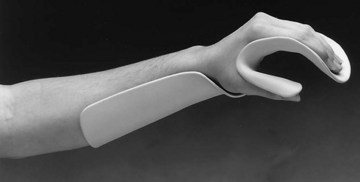
FIGURE 30-20 Single-surface static resting splint positions hand in 20-degree to 30-degree wrist extension, 45-degree to 60-degree metacarpophalangeal flexion, and 15-degree to 30-degree proximal interphalangeal and distal interphalangeal flexion.
A serial static splint achieves a slow, progressive increase in ROM by repeated remolding of the splint or cast. The serial static splint has no movable or resilient components, but rather is a static splint whose design and material allow repeated remoldings. Each adjustment repositions the part at the end of the available range to progressively gain passive motion. A cylindrical cast designed to reduce a PIP joint flexion contracture through frequent removal and recasting is a classic example of a serial static splint (Figure 30-21).
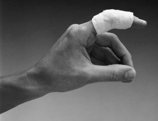
FIGURE 30-21 A series of cylindrical plaster casts is made to reduce flexion contracture at proximal interphalangeal joint.
Static progressive splints include a static mechanism that adjusts the amount or angle of traction acting on a part. This mechanism may be a turnbuckle, a cloth strap, nylon line, or a buckle. The static progressive splint is distinguished from the dynamic splint by its lack of a resilient force. It is distinguished from a serial static splint in having a built-in adjustment mechanism, so that the part can be repositioned at end range without the need to remold the splint. Generally, the static progressive mechanism can be adjusted by the client as prescribed or as tolerated (Figure 30-22).
Splints Classified by Purpose
Although nomenclatures may vary, the categories presented in the splint classification system (SCS) describe splints in functional rather than design terms.1 Splints are broadly described first as articular or nonarticular, and then by location and direction. The SCS then is divided into three overriding purposes of splints: restriction, immobilization, and mobilization. The publication also lists many functions of splints, each of which is placed in one of three categories. Splints may fulfill more than one function or purpose, depending upon the method of fabrication and the problems they address.
Restriction Splints: Restriction splints limit joint ROM but do not completely stop joint motion. One example is the splint in Figure 30-23, which blocks PIP joint hyperextension while allowing unlimited PIP joint flexion. Semiflexible splints are available that limit motion at the extremes of range but allow motion in the middle of the range. Although the splint may be restrictive, the goal or function of the splint may vary.
Immobilization Splints: Immobilization splints may be fit for protection to prevent injury, for rest to reduce inflammation or pain, or for positioning to facilitate proper healing after surgery. The classic example is the resting pan splint (see Figure 30-20), which serves two of the three functions. A resting splint fit for a client after a cerebrovascular accident (CVA) positions the wrist and digits to maintain soft tissue length and can protect the desensate hand against damage.
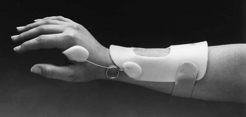
Mobilization Splints: Mobilization splints are designed to increase limited ROM or to restore or augment function. A mobilizing splint may assist a weak muscle or substitute for motion lost because of nerve injury or muscle dysfunction (Figure 30-24). The splint may attempt to balance the pull of unopposed spastic muscles to prevent deformity or joint changes and to assist function. A splint may provide resistance against which a weak muscle can exercise to improve its strength or to facilitate tendon gliding after tendon surgery. Frequently, mobilizing splints are used to increase the ROM of contracted joints, as in the case of Alexei, who experienced severe finger stiffness as a result of edema, which pooled in his hand after his forearm fracture.
Splints Classified by Design
After the purpose of the splint has been determined, the next decision relates to its design. Each of the types of splints described earlier (static, dynamic, serial static, and static progressive) may be fabricated as a single-surface design, a circumferential design, or a three-point design. A final category, the loop design, is generally limited to acting on finger IP joints by providing a loop of material that wraps around the joints to restore the final degrees of joint flexion.
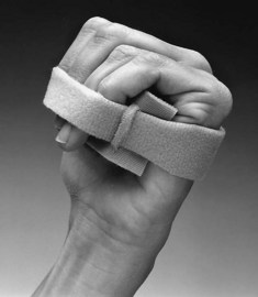
All splints are designed to provide some degree of force. This force may be distributed as a continuous loop, with equal and opposing forces wrapping around two or more joints (Figure 30-25, A). More commonly, the force is applied through three points of pressure (Figure 30-25, B). Although the loop design generally is used only on finger IP joints, some variation of the three-point pressure design is used in all other splints.
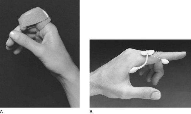
FIGURE 30-25 A, Final flexion strap designed to restore full interphalangeal joint flexion provides equal force on all surfaces of the digit. B, Three-point pressure splint with spring wire reduces proximal interphalangeal joint flexion contractures of 35 degrees or less.
Three-point finger splints that incorporate springs, spring wire, or elastics are often used to correct DIP and PIP joint flexion contractures. A flexion contracture exists when a joint will not move passively out of a closed position into extension. These designs include two points of pressure—one proximal to the joint and one distal—and the third or central opposing force, acting directly over or close to the joint, as in Figure 30-25, B. In a three-point finger splint, the force of the central point is equal to the sum of the two forces of the correcting points. This fact is clinically important because tissue tolerance under this central point may be insufficient and may react with pain and inflammation. This problem is seen frequently at the PIP joint, where limited surface area exists over which to distribute pressure. Pressure must be distributed with contoured surfaces that are as broad as possible, and the spring or elastic force and the wearing time must be adjusted to the client’s tolerance. Proper padding incorporated into the splint can aid in distributing pressure.
The dynamic finger-based three-point splint just described is a unique design that does not adhere to the 90-degree rule, that is, when the splint is applied to a joint with a flexion contracture, the angle of approach of the line of traction is never 90 degrees. The more severe the contracture, the greater the translational force that is present; therefore, it is less effective than a properly contoured outrigger splint that adheres to the 90-degree rule. This design should be fitted only in the presence of IP joint flexion contractures of 35 degrees or less. For finger contractures in excess of 35 degrees, a hand- or forearm-based outrigger splint is recommended because it can be positioned to apply force at a 90-degree angle of attack. Alternatively, a conforming, serial static splint can be used, as described in the section on traction.
Single-Surface or Circumferential Design: If a molded splint is to be fabricated, the next decision is whether to use a circumferential or single-surface design. Single-surface splints are fabricated to cover only one surface—the volar or dorsal surface of a limb, or the ulnar or radial half of the hand or forearm. Straps are added to create the three points of pressure necessary to secure the splint (Figure 30-26, A).
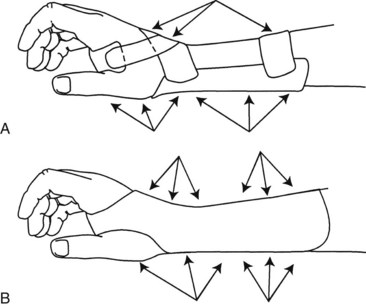
FIGURE 30-26 A, Single-surface splint requires properly placed straps to create three-point pressure systems to secure splint and ensure distribution of pressure. B, Circumferential splints create multiple three-point pressure systems to secure splint for immobilization.
Circumferential splints wrap around a part, covering all surfaces with equal amounts of pressure (Figure 30-26, B). Straps are used solely to close the splint or to create an overlap. Thinner materials can be used in molding a circumferential splint, because increased contours in the material add to the rigidity of the splint. An example of added strength from contours is corrugated paper. Consequently, circumferential splints can be made lighter and out of highly perforated materials for air circulation without sacrifice of control.
Indications for Single-Surface Splinting: Single-surface splinting is effective for supporting joints surrounded by weak or flaccid muscles, for instance, following a CVA or peripheral nerve injury. Because little or no active motion is available, the extra control given by circumferential splinting is not needed, and donning and doffing the splint will be easier. A single-surface splint is also effective as the base for attaching outriggers in dynamic splinting, and for postoperative splints in which fabrication of a circumferential splint may damage repaired structures.
Indications for Circumferential Splinting: Circumferential splinting is effective for immobilizing painful joints or for protecting soft tissue (see Figure 30-25, B). Because the circumferential design gives comfortable, complete control, it is particularly helpful when the client will be wearing the splint during activity, when shear forces can be a problem. This comfortable, complete control also makes a circumferential design useful for serial static splints used to reduce contractures. The control that a circumferential design supplies makes it a good design for stabilizing proximal joints when outriggers are applied to act on more distal joints.
When to Splint and When Not to Splint
A first step in deciding which splint style and design to choose is to determine whether the client is a good candidate for wearing a splint. Several issues should be examined in this regard.
Compliance Issues
First, the therapist must consider whether or not the client is likely to comply with the splinting program. The splint may have a negative effect on the client’s ability to be independent in self-care or to function at work. Some clients are sensitive about their appearance and may refuse to wear a splint if it offends their aesthetic sense or negatively affects their body image. Compliance with a splinting program may be poor if the client’s general level of motivation to get better is low. On the other hand, some clients are so highly motivated that they will overdo the splinting program and cause themselves damage. Finally, the client’s cognitive and perceptual ability to follow a splinting program should be considered, especially if no responsible care provider is available to supervise the splint-wearing precautions.
Ability to Don and Doff a Splint
Even if compliance is not an issue, the client may have problems donning and doffing (putting on and removing) the splint. For example, the client may have no one at home to assist in donning and doffing a difficult splint. The hospitalized client may not have adequate staff help to follow the wearing schedule or to apply the splint correctly.
Skin Tolerance and Hypersensitivity
The therapist must assess the skin condition of the client before deciding to fit a splint. Clients who experience diaphoresis and produce excessive perspiration that may lead to skin maceration need to be evaluated more carefully for splint consideration and type, such as ventilated plastics and absorbent padding. Some clients are intolerant of any pressure because of extremely fragile skin or sensory dysfunction. If these issues arise and cannot be ameliorated, safe alternative therapeutic interventions must be substituted for the splint.
Wearing Schedule
If none of the preceding issues prevents the client from being a candidate for splinting, the therapist must decide on the optimum wearing schedule for the splint. Nighttime may be the best time for a client to wear a static splint designed to change ROM. It is also the time when clients need resting splints to prevent them from sleeping in positions that may damage the hand or allow nerve compression. During the daytime, the client may wear a dynamic splint or a splint designed to assist function. It is often best to minimize splinting during the day if possible, so that the client can use his or her hand as normally as possible. For some who must wear positioning hand splints at night, it may be advisable to alternate wearing splints on one hand at a time so that the individual is not left without the sensory input and function of a splint-free hand. Such a splint-wearing schedule, although not ideal for meeting therapeutic goals, may at least offer a compromise for better compliance.
Splint Fabrication Process
Once the decision has been reached to fabricate a splint, arguably the most important step in the fabrication process is deciding on and creating a pattern. Although it may seem elementary even to the novice splint maker, this step can determine the success of the splint in terms of fit and function. Allowing the time to make a well thought-out and properly fitted pattern gives the splint maker the chance to deal with such issues as what he or she is trying to accomplish with the splint and how the splint is going to fit. Ultimately a properly fitted pattern will make the entire fabrication process easier and faster and will increase the chance of success.
OT Practice Note
The process of making a pattern involves an understanding of the anatomy and biomechanics of the hand and the materials to be used, in addition to a bit of old-fashioned dressmaking. Understanding how positional changes alter length and how depth and width relate to the pattern is paramount to success.
The common technique of making a pattern starts with a tracing or outline of the hand. This generally is taken with the hand lying flat when possible, or by tracing the uninvolved hand if necessary. An amount is added to this outline to approximate the width and length needed for the splint. A common error in this technique is not taking into account the position in which the hand (or other body part) will ultimately be held in the splint.
Figure 30-27, A and B, shows a pattern taken with the hand lying flat, with no length added to the pattern. In Figure 30-27, C, when the pattern is fit on the volar surface of the hand with the hand in functional position (the wrist in 35 degrees of extension, the MP joints at 70 degrees of flexion, and the IP joints in 10 to 20 degrees of flexion), the pattern extends beyond the fingertips and in fact is too long. The same pattern on the dorsum of the hand (Figure 30-27, D) with the wrist now in flexion illustrates that the pattern is now too short. Going from the volar surface of the hand to the dorsal surface is akin to driving around the inside of a curve as opposed to the outside of a curve. As any race car driver knows, the inside of a curve is the shorter distance. Altering the position of the hand and the surface to which the splint will be fit alters the length of the pattern. The splint maker must accommodate for this by checking the splint pattern on the hand in the position in which the hand will be splinted.
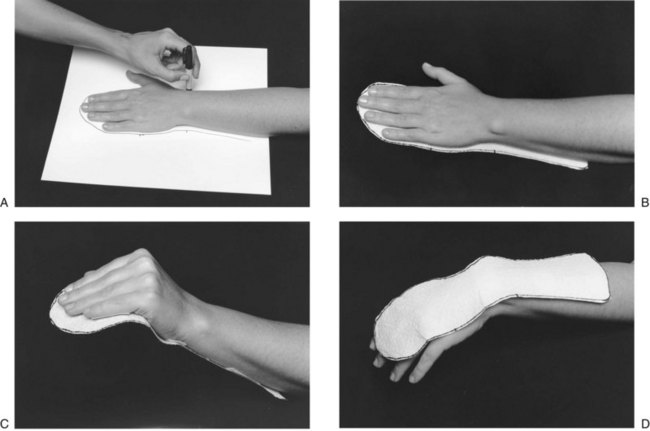
FIGURE 30-27 A, Tracing with pencil perpendicular to the arm creates a true size pattern. B, Pattern is full length with hand flat. C, Pattern is too long when fit on the volar surface with hand in resting position. D, Pattern is too short when fit on dorsum of hand with wrist and fingers in flexion.
Depth is the second dimension that must be considered when a pattern is made. The ideal trim lines of a single-surface splint fall at midline along the arm, hand, leg, or foot. A splint trimmed at midline provides optimal support and allows for proper strapping to help secure the splint in place (Figure 30-28).
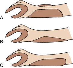
FIGURE 30-28 Forearm trim lines. A, Trim lines are too high, extending above forearm. Straps will bridge arm and will be ineffective. B, Trim lines are too low. Straps cannot substitute for too-low trim lines without applying excessive pressure. C, Midline trim lines ensure that straps properly secure splint on arm and hand.
To determine how much to add to the outline to achieve midline trim lines, the maker must observe the width and depth of the arm or hand. The forearm is cone-shaped, not a straight cylinder, and it graduates in depth over the forearm muscle. Even the thinnest forearm graduates in width and depth proximally. Persons with significant muscle bulk may have graduation at quite an acute angle from the wrist to the proximal forearm. Determination of how much to add to a forearm trough must consider how much the splint must come out, around, and up the forearm to reach midline. The depth of the hand, particularly the depth of the hypothenar eminence, must be known to create the proper trim lines for a hand platform.
In the fit of any forearm-based splint, the proximal trim lines must take advantage of the soft muscle bellies that protect the radius and the ulna. The proximal borders of the splint should be flared so that the trim line remains at midline to help secure the splint in place on the arm (Figure 30-29).
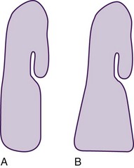
FIGURE 30-29 A, Narrowing the proximal pattern will cause trim lines to drop below midline. B, Flaring the proximal border of the splint maintains trim lines at midline.
A forearm-based splint should extend approximately two thirds of the length of the forearm, as measured from the wrist proximally. A good rule to remember is to bend the client’s elbow fully and mark where the forearm and the biceps muscle meet. The splint should be trimmed one-quarter inch below this point to avoid limiting elbow flexion, and to prevent the splint from being pushed distally when the elbow is flexed (Figure 30-30).
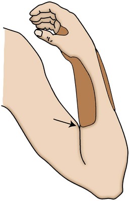
FIGURE 30-30 Length of forearm-based splint is checked by flexing elbow and noting where biceps meets forearm. Splint is trimmed  to
to  inch distal to point of contact.
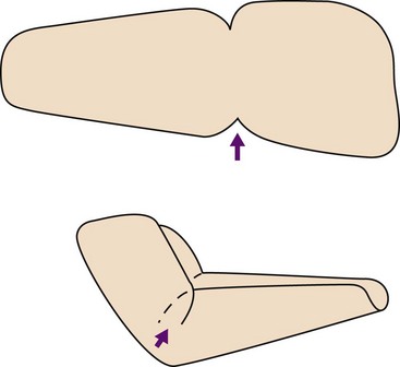
Most low-temperature thermoplastics used to make splints will stretch to conform around angles and contours. When a pattern is created that will go around an acute angle, such as a 90-degree angle around a flexed elbow or wrist, the pattern should include a dart, where the material can be overlapped without causing undue bulk (Figure 30-31). The pattern may be angled where necessary to accommodate acute angles. A well-fit and well-thought-out pattern translates to less material wasted, less expense, and shorter fabrication time.
Step Two: Choosing Appropriate Material
The materials commonly used for custom-fabricated splints are those in a family of plastic polymers that become pliable at a temperature low enough for the material to be molded directly onto the skin. The low-temperature thermoplastics (LTTs) currently available have certain characteristics that can be defined according to how a material reacts or handles when warm, and how it reacts once molded.
Choosing the optimal material for a given splint application can make the difference between a quick and easy splint-making process and one that requires extensive adjustments and reheating. It behooves every splint maker, novice to advanced, to sample a variety of materials and test the handling characteristics, so that no surprises occur when a material is heated and is ready to be cut and fitted to a client.
Characteristics of Splint Materials: Each LTT has some handling characteristics that apply when the materials are warm and pliable, and others that apply when they are cold or molded. Following is a list of the most common characteristics and a description of how each contributes to the choice of a material for a specific application.
Resistance to Stretch: Resistance to stretch describes the extent to which a material resists pulling or stretching. The greater the resistance, the greater is the degree of control that the splint maker will have over the material. Materials that resist stretch tend to hold their shape and thickness while warm and can be handled more aggressively without thinning. More resistant materials are recommended for large splints and for splints made for persons who are unable to cooperate in the fabrication process. In contrast, the less resistance to stretch a material has, the more the material is likely to thin during the fabrication process, and the more delicately it must be handled. The advantage of stretch is seen in the greater degree of conformability attained with less effort on the part of the splint maker.
Conformability or Drape: Resistance to stretch and conformability or drape describe nearly the same characteristic, that is, if a material stretches easily, it will have better drape and conformability. The great advantage of materials with a high degree of drape or conformability is that with a light, controlled touch or simply the pull of gravity, they readily conform around a part for a precise fit. The disadvantage of materials with a high degree of drape (and generally also low resistance to stretch) is that they tolerate only minimal handling, and care must be taken to prevent overstretching and fingerprints in the material. Materials with a high degree of drape are not recommended for large splints or for uncooperative clients. They are ideal, however, for splinting postoperative clients when minimal pressure is desired, and for dynamic splint bases, in which conformability secures the splint against migration (movement distally) when components are attached. Materials with a low degree of drape must be handled continuously until the materials are fully cooled to achieve a contoured fit; often they will not conform intimately around small parts such as the fingers.
Memory: Memory is the ability of a material, when reheated, to return to its original, flat shape after it has been stretched and molded. The advantage of high memory in a material is that the splint can be remolded repeatedly without thinning and weakening of the material. Materials with memory require handling throughout the splint-making process because until they are fully cooled and molded, they tend to return to a flat shape. This and the slightly longer cooling time of materials with high memory can be used to advantage with clients who require more aggressive handling to achieve the desired position. Disadvantages of materials with excellent memory are their tendency to return to a flat sheet state when an area is spot heated for adjustment, and their need for longer handling to ensure that they maintain their molded shape until fully cooled.
Rigidity vs. Flexibility: Rigidity and flexibility in cold splint material are terms that describe the amount of resistance a material gives when force is applied to it. A highly rigid material is very resistive to applied force and may, with enough force, break. A highly flexible material bends easily when even small force is applied to it, and it is not apt to break under high stress. Materials are available that fall all along this continuum.
Generally, the thicker a thermoplastic and the more plastic its formula contains, the more rigid the material will be. Thermoplastics come in thicknesses ranging from  inch (3.2 mm) to as thin as
  inch (1.6 mm). Thinner materials and thermoplastics that contain rubber-like polymers in their formula tend to have greater flexibility in their molded state. Flexibility in a material allows for easier donning and doffing of splints and may be desirable for clients unable to tolerate the more unforgiving rigid materials. Rigidity is also a factor of the number and depth of contours included in the design. The same material may yield a semiflexible splint when used to make a single-surface splint with shallow contours, or a rigid splint when used to make a tightly filled circumferential splint.
Bonding: Bonding is the ability of a material to adhere to itself when warmed and pressed together. Many materials are coated to resist accidental bonding and require solvents or surface scraping to remove the coating to bond. Uncoated materials, which require no solvents or scraping, have very strong bonding properties when two warm pieces are pressed together. Self-bonding is helpful when outriggers or overlapping corners are applied to form acute angles, but can be a problem if two pieces adhere accidentally.
Self-sealing Edges: Self-sealing edges are edges that round and seal themselves when heated material is cut. This characteristic produces smooth edges that require no additional finishing, which adds time to the fabrication process. Materials with little or no memory and high conformability generally produce smooth, sealed edges when cut while warm. Materials with memory and those with high resistance to stretch resist sealing, requiring additional finishing.
Soft Splint Materials: Soft, flexible materials such as cotton duck, neoprene, knit elastics, and plastic-impregnated materials may be used alone or in combination with metal or plastic stays to fabricate semiflexible splints. These materials allow fabrication of splints that permit partial motion around a joint, yet still limit or protect the part. Semiflexible splints sometimes are used during sporting activities and to assist clients with chronic pain in returning to functional activity. Semiflexible splints are also used for geriatric clients and for clients with arthritis, who often cannot tolerate rigid splints.
Neoprene splints can be fabricated with the use of sealing glue or iron-on tapes. Careful attention must be given to the patterns for soft splints, because the support they offer relies primarily on achieving a secure fit without gapping or excess material. Most other soft materials require sewing, and the fully equipped OT department should include a sewing machine. A sewing machine is useful for adapting and adjusting prefabricated soft splints to ensure that each splint that leaves the clinic is indeed custom-fit, if not custom-fabricated.
Choosing the Best Category of Material for the Splint: Although an experienced splint maker can make many types of splints from the same material, it is better to choose a material with appropriate handling characteristics for the type of splint being made. The following list can be used as a guide from which to start choosing materials for different applications. The availability of materials and the experience level of the therapist assist in determining the most appropriate material.
Forearm-Based and Hand-Based Splints: Splints need close conformability around a part when they serve as a base for a dynamic splint, stabilize a part of the body, reduce contractures, remodel scar tissue, or immobilize to facilitate healing of an acute condition. Such splints should be made from a material with a high degree of conformability to achieve a conforming fit. When conformability is not crucial, the splint can be made from a material with high resistance to stretch and low to moderate drape. Splints fabricated for burns and other acute trauma do not require as conforming a fit and can be made from low-drape materials. Materials that resist stretch and tolerate aggressive handling are recommended for positioning of a spastic body part, because such materials will not stretch and thin during the splint-making process. Experienced OTs who work without a formal pattern choose a material with a higher degree of drape and conformability and allow gravity to assist in the splinting process.
Large Upper and Lower Extremity Splints: Long splints fabricated for the elbow, shoulder, knee, or ankle generally should be made of materials that have high resistance to stretch, to provide the control necessary for dealing with large pieces of material. Such splints generally do not need to be highly conforming because they are molded over broad expanses of soft tissue. Care must be taken to provide relief for bony prominences, or to provide padding to distribute pressure.
Circumferential Splints: A splint designed to wrap all the way around the part should be fabricated from materials that have a high degree of memory and that tolerate stretching without forming thin spots. The materials should be highly perforated, thin, and able to be stretched evenly. After being stretched, these materials will cinch in around the body part while still allowing sufficient flexibility for easy donning and doffing. These materials work very well for fracture bracing and for circumferential splints that are used for contracture reduction and for stabilizing or immobilizing joints. Another choice for making less restrictive circumferential splints is the use of semiflexible materials, which facilitate easy donning and doffing and allow limited motion within the available arc of motion.
Serial Splints: Serial splints that require frequent remolding to accommodate increases in joint range of motion should be made from a material that has considerable memory or is highly resistant to stretch, to avoid thinning with repeated remolding. The chosen material should have moderate to high rigidity when molded to resist forces from contracted joints or from spastic muscle tone.
Step Three: Choosing the Type of Traction
All splints provide some form of traction to move or stabilize a joint or joints. The traction mechanism may be dynamic, using a spring, hinge, or elastic. Traction may also be static, employing straps or turnbuckles or involving remolding of the splint base itself. If the mechanism moves or is resilient, the splint is called a dynamic splint, and if it does not move, the splint is called a static splint. The following section describes the various options for applying traction and discusses appropriate uses of each option.
Dynamic Traction: The purpose of dynamic splints is mobilization of a joint through the use of a resilient force attached to an outrigger, or through the use of a spring coil. Each mechanism of force has advantages and disadvantages that make it suited for some uses and ill-suited for others. Construction techniques differ substantially when spring coils are used versus outriggers with elastic components. Thus, the indications for each style of splint vary.
Spring coils are best suited to assist weak muscles or to substitute for paralyzed muscles (see Figure 30-24). Clients with weak or paralyzed muscles will likely require the splint for a long time and will wear it while working or performing their ADLs. The low-profile, lightweight construction of a coil splint is recommended because it is less likely to interfere with hand function. Spring coils retain their force and alignment over time, rarely require adjustment, and are ideal for long-term conditions.
Splints with outriggers are the optimal choice for splinting postoperative clients (Figure 30-32). These splints allow frequent adjustments to maintain correct positioning and to accommodate changes in bandage thickness and edema as healing and rehabilitation progress. The postoperative client will likely use the splint for only a short time, generally 4 to 6 weeks. Such a client will not be returning to normal functional activities with the affected hand during that time. Thus, the bulkiness and limited function associated with an outrigger splint are relatively unimportant, but it is vital that the splint be able to be self-donned, because it is usual for the client to remove it for periods of time or to alternate it with other splints. Alexei’s dynamic extension outrigger (see Figure 30-18) is an example of this. He alternated it with his dynamic flexion outrigger and discontinued it after 3 weeks, when his extension goal was met.
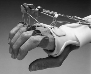
FIGURE 30-32 Easily adjustable Phoenix outrigger with slotted pulleys allows frequent changes in angle of approach.
Splints with outriggers are also used for contracture reduction. For this purpose, they are generally most effective when used during the early stages of healing, when the contracture feels soft and is easy to reduce.9 Frequently, clients at this stage still have pain and inflammation. They cannot tolerate a rigid, static splint, but they will tolerate a light force provided by an outrigger.
Static Traction: The overall purpose of static traction splints is to apply traction to immobilize or restrict motion. When static splints immobilize, they are protecting, resting, or positioning. When they restrict, they are blocking motion, aligning joints, or limiting motion. When static splints are used to mobilize, they are used in a serial static or static progressive fashion to reduce contractures and remodel scars.
Serial Static Traction: A serial static splint is fabricated by repeated adjustments that position a joint at its end range of motion each time to achieve slow, progressive increases in ROM. For example, a cylindrical cast made for gaining PIP extension must be remade after a time (usually 1 to 3 days) to reposition the joint at the end of its range of motion (see Figure 30-21).
Static Progressive Traction: A static progressive splint requires a built-in mechanism for adjusting the traction. Choosing which mechanism to use, be it a turnbuckle, a Velcro strap, or a buckle (see Figures 30-22 and 30-25, A), depends on availability, the therapist’s experience, and the client’s ability to manage the mechanism. A good rule to follow is to choose the simplest component that will achieve the desired goal.
Serial static splints and static progressive splints each have certain advantages and disadvantages. Serial static splints are useful for difficult clients who have high muscle tone, or who are cognitively impaired and would have problems with the adjustment mechanisms. This splint choice also gives the therapist the control necessary for clients who are noncompliant, or who would be overly zealous and would apply too much force. Disadvantages are that the splint requires more therapist time because it must be remolded many times, and if the client does not remove it for several days, some ROM may be lost in the direction opposite to that in which the splint is applying force.
Advantages of a static progressive splint are that the therapist has to make only one splint, and that reliable clients with normal muscle tone may make more rapid progress because they can tailor the adjustment to their own pace and tolerance. The disadvantage of a static progressive splint is that it cannot be used on the client who has abnormal tone, or who is unreliable.
Implications of Application of Force: All splints, whether static or dynamic, apply force and to some degree stress on the structures they contact. The unimpaired hand tolerates a wide range of stresses by adaptation when possible and by avoidance when not. The client with sensory or cognitive impairment may lack the protective responses necessary to reposition the hand away from stresses applied by splints.
Pressure causes ischemia (localized anemia caused by obstruction of blood supply to tissues), and pressure is increased when splints are contoured too sharply, when they do not conform uniformly, or when they do not cover a broad enough area of soft tissue. Splints that migrate or move on the hand because of insufficient strapping or contouring may actually apply pressure in areas that the splint was designed to relieve.
Amount of Force to Apply: How much force can be applied safely? No absolute rules exist regarding the amount of force that can be applied for immobilization, or to a restricted joint to produce motion. The splint maker must apply sufficient force to create motion, but not so much as to cause ischemia. Much depends on the degree of the contracture, how long the restriction has existed, the age of the client, and the location of the restriction. This leaves the therapist with several options when choosing which force and how much force to apply.
For example, external force in dynamic splints generally is applied through the addition of rubber bands, elastic, or springs. No option is ideal, and all require careful selection, frequent adjustment, and client education on frequent skin checks. The amount of force supplied by rubber bands and springs depends on their thickness and their length. The thickness of the band or spring determines its potential force, whereas the length of the band or spring (or the number of coils in the spring) determines the ROM through which the force can be applied. When bands or springs are used, it is desirable to use the optimal force (i.e., the greatest tolerable force over the longest wearing time) that does not produce ischemia. To accomplish this, the midrange of the bands or springs should be used, rather than their end ranges, which may be too slack or too strong. A gauge is available for measuring the applied force of elastic, which generally should be between 100 and 300 g.
Techniques are available for avoiding pressure areas and shear forces in a dynamic splint, particularly when traction is applied to mobilize a finger joint. First, the joint(s) proximal to the finger joint being splinted must be stabilized. For instance, to mobilize a PIP joint with an outrigger and cuff, the MP joint must be held securely, so that no movement occurs to cause the splint to produce pressure points elsewhere on the hand or digits. Care must be taken in contouring the splint around the proximal phalanx, to distribute pressure and prevent motion that could cause shearing over the dorsum of the finger. In this case, padding may be necessary to help distribute pressure over the small and thinly padded phalanx (Figure 30-33).
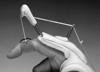
Duration of Traction: Basic to answering the question, “How long should traction be applied?” is an understanding of theories of tissue stretching versus tissue growth. Three key concepts aid in the understanding of these two different tissue responses. First, all materials, including human tissue, respond to applied stress. If stress is applied over time and then is relaxed, the tissue will no longer return to its original shape but will adapt to the new shape. This stretching phenomenon in skin is a result of its plastic behavior and is known as creep. The lengthening that occurs with creep is found to be the result of “a slippage of short collagen fibers on one another within the tissue. Some fibers may rupture, while others just slide on each other.”8
The second concept is that of the elastic limit of tissue. Think of pulling on a rubber band. As the band is pulled, tension increases until the elastic limit is reached. If pulled beyond its elastic limit, the rubber band will break. In clinical terms, the end of the elastic limit is the point of tissue elongation at which pain will be felt and tissue damage may occur. Stretching tissue beyond its elastic limit does not lead to permanent lengthening, but it does cause unwanted tearing and probable further tissue contracture.8 For creep to occur in living tissue, traction must hold the skin with sufficient force to exceed the elastic limit of the skin. This may cause tearing of small fibers, which leads to inflammation and additional scarring caused by fibrogen deposits.
The third concept is tissue growth. True growth occurs when “living cells will sense strain and collagen fibers will be actively and progressively absorbed and laid down again with modified bonding patterns with no creep and no inflammation.”8 This is the aim of splinting when the goal is contracture reduction or lengthening of restricted soft tissue.
Two approaches may be used to apply traction to lengthen soft tissue and reduce contractures. One approach is to position the tissue at the end range of its elastic limits and hold it statically for short periods, and then to relax and reposition it frequently. This approach is termed stress relaxation.7 The second approach is to apply force within the elastic limits of the tissue, hold it for a long period, and then reposition it. Differences between these two approaches include time and ability to judge the elastic limits of tissue. The first approach relies on principles of stress relaxation, which theorize that tissues reach their elastic limit over a shorter period with frequent repositioning and will retain this newly set limit over time.7 The second and more commonly used approach relies on the application of a low load over a long time to allow tissue growth to occur. Both approaches have merit, and it is up to the therapist, who develops this skill with experience over time, and the prescribing physician to determine the appropriate approach in each instance.
Step Four: Choosing a Splint Design for a Given Purpose
Mobilizing Splints to Remodel Scar Tissue and Reduce Contractures: Scar tissue is one of the major contributors to deformity or joint changes. Any time an insult to tissue occurs, as after an open injury or after surgery, scar tissue is produced by the body to heal the wound. The scar may be subcutaneous, superficial, or both. When it is subcutaneous, it often results in loss of motion, because scar tissue acts like glue, keeping tissue planes from gliding. Scar also contracts; when this contracture occurs over a joint, loss of joint motion results. To restore motion, scar tissue must be remodeled, that is, it must be softened and lengthened. If the contracture is caused by shortened soft tissue that is not scar, that soft tissue must also be lengthened. The process is the same for scar or soft tissue.
The effectiveness of splinting for remodeling scar and reducing contractures can be increased greatly by application of a deep heat modality, such as paraffin or moist heat, before application of the splint. When tissue is unheated, it is less elastic, meaning that it has a great deal of tension and is difficult to elongate. With the application of heat, tissue becomes temporarily more elastic, meaning that tension in the tissue is reduced and the tissue is much easier to elongate.
Many approaches are available for splinting for remodeling scar and reducing contractures. Three-point splints can be used for flexion contractures (extension ROM is decreased), loop splints for IP joint extension contractures (flexion ROM is decreased), and outriggers for MCP extension contractures (lack full flexion ROM at the MCPs). Dynamic outriggers can be used to reduce early, soft tissue contractures, particularly when the client cannot tolerate a static splint. Static progressive splints or static splints can be used in a serial fashion.
Immobilizing and Restrictive Splints for Pain Reduction: Of the many uses of splints, perhaps the most common is to limit or reduce pain by providing rest and support. The most common splint prescriptions are written for splints to reduce the pain caused by the inflammatory processes of tendinitis or after sprain or strain injuries.
Several questions help determine which splint will best serve the client’s needs. First, if the injury is caused by an acute sprain, the choice may be an immobilizing splint until pain and edema have subsided. If the pain is chronic in nature and is caused by the performance of a particular activity, a semiflexible splint may serve best. A semiflexible restrictive splint may sufficiently reduce pain by limiting ROM, yet still allow function without increasing stress on unaffected joints or tissue (Figure 30-34).
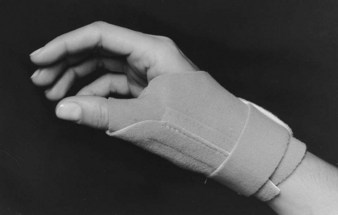
A second question concerns the need for full-time splinting versus intermittent wear. In the presence of an acute injury with orthopedic involvement or tissue damage, the splint may need to immobilize and to protect the part from further damage. Here, client tolerance and compliance will in part determine material and design choice. The therapist may also need to consider the integrity of the tissue and the need to accommodate bandages and bandage changes. If the splint is indicated only for intermittent wear, the design choice may depend more on the client’s ability to readily don and doff the splint. The choice of materials may be dictated by the functional needs of the client. For intermittent splints used for vocational activities, lightweight, well-aerated materials may be indicated. For intermittent splints used for positioning, such as a resting splint designed to maintain functional position between exercise sessions, stronger materials may be indicated, and perforations may not be necessary.
A third important question in deciding on a splint design is, “What structures need to be immobilized or supported, and which should be left free?” When protective or pain-reducing splints are provided, care must be taken to splint only the involved structures without impeding motion elsewhere. If the purpose of the splint is to rest the tendons at the wrist to reduce inflammation, the splint must not limit carpometacarpal (CMC) or MP joint motion if these structures are not symptomatic. If used during the performance of ADLs, splints that fully immobilize a joint may transfer stress to joints proximal or distal to the immobilized joint. For this reason, semiflexible splints that restrict only end ranges of motion may be indicated during activity, whereas an immobilizing splint may be indicated for total rest at night.
Immobilizing Splints for Positioning: One of the splints most frequently fabricated by OTs is the resting pan (also known as the resting hand or functional position splint), which is used to maintain the hand in a functional position (see Figure 30-20). The purpose of this positioning splint is to keep the soft tissues of the hand in midrange to maintain optimal mobility and to prevent shortening of the soft tissue structures around the joints. Occasionally, positioning splints are prescribed to position joints at end range to prevent contractures in the presence of severe tissue damage, as with burns. The important decision involves determining the optimal position for the most functional outcome.
Positioning splints may be fabricated for temporary use after surgery and may require frequent adjustment to accommodate changes in edema and bandages. The materials chosen for these splints should have memory to allow for remolding while keeping their thickness and strength. The choices of a dorsal versus a volar-based splint and a single-surface versus a circumferential splint depend on surgical and wound sites, the need for ease of donning and doffing, the client’s available sensation, and the therapist’s and physician’s preferences and experience.
Step Five: Fabrication
The fabrication processes for single-surface and circumferential splints differ significantly. They do have a starting point in common: the pattern from which the splint will be made. Starting with a paper pattern is recommended, particularly for the novice splint maker. One very basic rule of splinting is to get the pattern right before beginning to work with plastic. It is far less expensive to discard a few pieces of paper than even a small piece of LTT. Also, if one saves the paper splint pattern in the client’s chart, it is easy to use to fabricate another should the splint be lost, or to enlarge it as a pediatric client grows. Pattern making, design principles, and principles of fit are important components of knowledge for splint fabrication; these concepts can be learned by the novice splint maker by going online to the Evolve Website associated with this publication, or by referring to a book such as Hand and Upper Extremity Splinting: Principles and Methods.11
Fabrication Techniques for Single-Surface Splinting: Single-surface splints cover the volar surface, the dorsal surface, the ulnar half, or the radial half of the arm and hand. Generally, single-surface splints have gentle contours and cover as broad an area of tissue as is feasible to distribute pressure. The following steps should be used as a guide in the process of creating a single-surface splint. For the sake of demonstration, the single-surface and circumferential splints described and pictured are wrist extension (cock-up) splints (Figure 30-35, A):
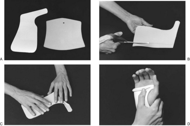
FIGURE 30-35 A, Pattern for single-surface cock-up splint on left requires precision for a proper fit. Pattern on right for circumferential splint does not need precise fit because material stretches and overlaps to achieve proper size. B, Support material on table to prevent stretching, and cut with long strokes of scissors. C, Fold edges of material and gently press flat to create thin, smooth edges that distribute pressure better. D, Gently support the wrist at all times to achieve proper fit.
1. Except for the fingers,  -inch–thick material is recommended to obtain sufficient rigidity to hold the joint firmly in position. The broad contours of single-surface splints require thicker materials to provide sufficient support.
2. Etch the pattern onto the cold thermoplastic material with a scratch awl or wax pencil before placing the material in a hot water bath. The water temperature required for most materials to soften properly is approximately 160° F. Temperature and time will vary, depending on the material and its thickness; this information is typically provided by the material’s manufacturer in the accompanying literature. Most materials heat to the pliable stage in 1 to 2 minutes.
3. Carefully remove the material from the hot water bath and lay it flat on the table for cutting. To prevent stretching, avoid holding material unsupported while cutting (Figure 30-35, B).
4. Starting at the neck of the scissors, cut with long, even strokes to prevent jagged edges.
5. Reheat the material if it has cooled too much to be formed. Place the material on the forearm and hand with the forearm in supination so that gravity can assist the initial molding. Some therapists prefer the elbow propped on a table with the hand in the air if the client is compliant. Check that the trim lines fall at the midline. If they do not, mark where excess material needs to be removed. Trim the material before it cools. Note areas that will need to be folded for clearance and for creation of smooth edges. Fold and secure the edges firmly in place (Figure 30-35, C).
6. Reposition the splint on the forearm. Maintaining control on the wrist and forearm sections, carefully pronate the forearm. Maintain the wrist in extension at all times. The tendency for the wrist to drop into flexion when the forearm is pronated is universal. Controlling the wrist will ensure that the desired wrist position is maintained at all times (Figure 30-35, D). If necessary, rotate the forearm section to ensure that the trim lines are at midline. Refer to Figure 30-6 to review the importance of the changing shape of the forearm from a supinated to a pronated position.
7. Allow the splint to cool until it holds its shape. It does not have to be held in place until completely cold. Remove the splint. Heat and smooth any rough edges as needed, and apply the straps.
8. Strapping is critical to secure the splinted part in the splint and to diminish shear forces and the possibility that pressure areas may develop. The splint may require several straps; wide or crossed straps are suggested to obtain the necessary control. Because the forearm is cone shaped, straps placed straight across the forearm will contact the skin effectively only on their proximal surface (Figure 30-36). To have the forearm straps apply effective and well-distributed pressure, you may consider placing them at an angle.
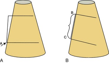
FIGURE 30-36 Forearm is cone shaped, gradually widening from wrist to elbow. A, Strap laced straight across broader proximal forearm contacts skin only at point A and does not secure splint. B, Strap placed at angle applies even pressure along line BC to secure splint.
9. Single-surface splints rely on strapping to hold them in place and to create one or more three-point pressure systems to securely hold the joint or joints being splinted (see Figure 30-25, B). For straps to function properly, trim lines must fall midline along the arm and hand. If the trim lines are left too high, making the trough too deep for the part, the straps will bridge the part and sit up on the edge of the splint, where they are ineffective. The most effective way to secure a splint in place on the forearm is to apply pressure through the splint onto the soft tissue of the forearm muscle bellies. If the forearm trim lines angle below the muscle bellies, the splint will no longer be secured on the muscle bellies.
10. Instruct the wearer regarding the wearing schedule and proper care of the splint. To prevent ischemia and shear forces, check the fit of the splint regularly.
Fabrication Techniques for Circumferential Splints:
1. Use a thin or highly perforated elastic material or a flexible rubber material that has some memory. For hand- and forearm-based splints, thin elastic materials ( -,
-,  -, or
-, or  -inch) provide sufficient strength because of the rigidity provided by the curves of the splint. For splints covering larger areas, a highly perforated
  -inch material is recommended. Materials for circumferential splints should be coated to prevent permanent adherence when warm or should be able to be pulled apart once cooled.
2. Etch the pattern onto the material. Because the materials for circumferential splints are generally stretched to contour around the arm, the pattern does not need to be as precise as for a single-surface splint. It is important to know how much the material will be pulled and if it will be overlapped or finished edge to edge, so that a piece of sufficient size is cut (Figure 30-37).
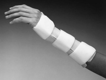
3. Wrap the material all the way around the part being splinted. Two techniques can be used to create closure for a circumferential splint. The first is to pull the material around the part and pinch the remaining material together to create a seam. Gently tug on the seam to conform the material. When the material is cool, open the seam and trim the splint. The second technique is to overlap the two ends to form a flap (Figure 30-38). To prevent the flap from adhering (this may happen when the coating is thinned as the material is stretched), wait until it has cooled slightly before overlapping.
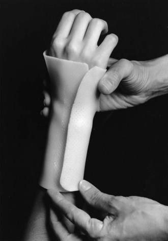
FIGURE 30-38 Circumferential splint made from flexible material with overlap for easy donning and doffing.
4. Smooth edges as necessary. The circumferential splint creates multiple three-point pressure systems by virtue of its design, and strapping is used only to hold the splint firmly closed.
Fabrication and Fitting of Semiflexible Splints and Prefabricated Splints: Materials used in the fabrication of semiflexible splints include neoprene, cotton duck, woven elastics, and thermoplastic-impregnated materials. Neoprene splints are generally fabricated with use of a special glue that adheres pieces together at the edges. The patterns for neoprene splints must be precise to achieve a conforming fit. Cotton duck and other woven materials require sewing and considerable skill in pattern creation and the addition of darts to ensure a good fit. Very thin thermoplastic materials can be used to create semiflexible splints, and certain patterns can be adapted to allow for partial range of motion within a splint.
Many commercially prefabricated splints are made from woven materials, because these materials present the broadest range of size adjustability and are less likely to require custom fabrication. It is highly recommended that even a prefabricated splint should be custom fit by a therapist to ensure proper fit and adherence to an appropriate wearing schedule. A well-supplied splint department should include a sewing machine for use in custom fitting all splints. Remember that it is the therapist’s responsibility to take the time to develop the skills needed to ensure that even prefabricated splints fit the client as if they were custom made.
Threaded Case Study
Alexei, Part 2
Using the Occupational Therapy Practice Framework, the evaluation of Alexei began with an occupational profile to establish his needs, priorities, and goals, which included the ability to administer his own medications and to be independent in his ADLs so he could return to his independent living apartment. Analysis of Alexei’s occupational performance identified his inability to grasp small objects such as insulin syringes and a glucose level tester, and to perform ADLs such as grasping a normal eating utensil or toothbrush, zipping his pants, or taking money from his wallet. Alexei demonstrated problems within the performance skills category, including poor coordination of motion and difficulty manipulating objects. Under the category of client factors, problems with his right dominant hand included lack of ROM and the mobility required for successful task performance. The personal (or internal) contexts supporting Alexei that were identified during the evaluation revealed his flexibility and intelligence, his engaging and assertive communication style, his ability to learn an exercise regimen and how to use complex splints, his history of successfully managing health-related problems such as diabetes, his strong motivation to remain independent in his own apartment, and his psychological need to live in a place that would allow him to have a companion pet. His external contexts, including physical and social contexts, both supported and interfered with Alexei’s achieving his goals. Positive aspects included his living in a full-service senior housing complex, a supportive nursing staff at his complex willing to help him regain independence, and an administrator at the complex who was willing to modify the rules slightly to support Alexei’s goal of returning to his apartment in the independent living section of the complex. Negative aspects of these contexts included lack of adequate transportation to therapy and the living site’s strict procedural rules that residents must stay in the least restrictive setting.
What would have happened to Alexei if OT intervention had consisted of just therapy sessions with no dynamic splinting? ROM gains achieved during therapy probably would not have been maintained. The intervention plan of dynamic splinting was established on the basis of Alexei’s limited ability to get to therapy appointments, coupled with his ability to carry out much of his rehabilitation on his own or with the assistance of nursing staff at the assisted living complex.
How critical was the team approach, and how important was ascertaining the client’s main goal during the initial evaluation? The outcome was ultimately successful because (1) a collaborative relationship was formed between the very motivated client, the OT, and the nursing staff, with all participants focusing on and working toward the goal of retraining Alexei in independent medical management, and (2) the complex administrator agreed to bend the rules for a month until Alexei’s goal of complete independence could be achieved. Without a focused goal, much therapy time could have been lost working toward gains less important to the client, which may have ultimately robbed him of his independence.
Section 2 Suspension Arm Devices and Mobile Arm Supports
Threaded Case Study
Manny, Part 1
Manny is 31 years old. He has been married for 5 years and has a 3-year-old daughter. He had been working for 5 years in a law firm with 20 attorneys. He incurred a complete C5 level spinal injury in an auto accident 1 month ago. He is currently in a rehabilitation center in the city, where he lives and worked. Upon arrival at the rehabilitation center, his early expectation was that he would recover from his spinal cord injury. However, as the medical staff described to him evidence of a complete fracture dislocation in the cervical spine, Manny began to think that he would need the ability to perform selective occupations in an adaptive manner to resume life in the community where he resided before his injury occurred.
In an OT assessment in which the Canadian Occupational Performance Measure was used, the client was asked to identify the most important occupations in which he would like to participate upon his return home. The occupation of greatest importance to Manny was to resume his law practice. This occupation was of primary importance so that he could financially support his family and regain his sense of integration back into the community. This meant that he would have to be able to manage the occupations of written communication, phone use, computer use, and essential activities and basic ADLs (i.e., self-feeding, pressure relief, and independent mobility) in the office. He also felt that he needed to resume the role of father by being able to play with his child, and he wanted to be able to participate in social activities with his wife, such as attending dinners in restaurants. Upon admission, Manny was unable to participate in any of the occupations just listed. In terms of his performance skills, his upper extremity strength was 2 (poor) in the proximal muscles, 2 (poor) in elbow flexion, 0 in elbow extension, and 0 in skeletal muscles distal to the forearm. Manny’s sensation was partially absent in the upper arm and completely absent in the elbow distally. Because of appropriate intervention during his admission to an acute care facility, his passive range of motion throughout his stay was within the functional range.
1. Given Manny’s performance skills, would any equipment enable him to resume his most important occupation of practicing law? What is this equipment?
2. How would you approach discussion with this client regarding equipment needs for his return to work?
3. What series of interventions will you provide to enable Manny to return to his law firm, where the partners are concerned about his ability to manage the many aspects of the job of an attorney?
Suspension arm devices and mobile arm supports are commonly used and can fulfill several treatment objectives for the person with severe physical disability. These devices can support the shoulder and forearm, encourage motion of weakened proximal musculature, prevent disuse atrophy, prevent loss of ROM, provide pain relief, provide proximal support for distal function, and enable occupational performance.
Suspension Arm Devices
Suspension arm devices are suspended from above the head, generally on an overhead suspension rod that most often is attached to a wheelchair. They also can be attached to regular chairs, a child’s highchair, a body jacket, or even an overhead track used for walking clients.6 Without the suspension rod, they are attached to over-bed frames to allow the client to use the device while in bed. These suspension arm devices were found in OT clinics as early as the 1940s. Ease of management, low cost, and ability to support proximal weakness of the upper limb contributed to their early popularity,19 and they continue to be used for selected purposes.
Purposes
Suspension arm devices may be used to meet some of the following objectives:
• To position the shoulder girdle musculature to allow distal muscles to engage in occupational performance
• To assist and support below fair-grade (F or 3) shoulder girdle musculature
• To allow gravity-eliminated exercise for weak shoulder girdle musculature
• To encourage increased ROM through repetitive activities19
• To prepare clients to use mobile arm support (MAS) by encouraging weak proximal musculature to move
• To support a painful shoulder
• To position an edematous hand away from a dependent position
Suspension arm devices generally are more effective for positioning and exercise than for occupational performance because of the mechanical principles on which they operate. The upper limb swings as a pendulum from straps or springs attached to the suspension rod; this makes it difficult to make fine adjustments in movement.19
Variations in Suspension Arm Devices
Several variations of suspension arm devices are available. The overhead rod may be the same, but the attachments to the rod reflect variation. The variations discussed here are commercially available and are in current use.
Suspension Sling: The suspension sling (Figure 30-39) has a single strap (A) suspended from the suspension rod (B). A horizontal bar (adjustable balance bar, JAECO Orthopedic Inc., Hot Springs, Ark.16) with holes for adjustment of the fulcrum (C) supports the two leather suspension slings (D). These slings provide support for the wrist and elbow separately. The adjustable suspension mount (E) is attached to the wheelchair and holds the suspension rod.
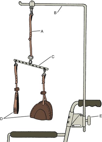
Suspension Arm Support: The suspension arm support (JAECO16) (Figure 30-40) has a forearm support that is the same as that used in the mobile arm support. It is suspended from a single point on the suspension rod. This device can be used as an initial step for the client who can benefit from an MAS and is easily applied to the wheelchair. It can be easily attached and adjusted to over-bed frames to allow clients who are confined to bed to perform tabletop activities, in addition to hand-to-face occupations, with this device (Figure 30-41). However, it does not have the fine adjustment capabilities of the MAS, which extremely weak clients need. With a special mount (Figure 30-42), the suspension arm support is easily adaptable to the reclining wheelchair. This feature makes it useful during the rehabilitation of clients who cannot yet sit fully upright.
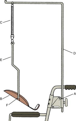
FIGURE 30-40 Suspension arm support. A, Adjustable suspension mount. B, Forearm support. C, Springs. D, Suspension rod. E, Suspension bar. F, Rocker arm (offset swivel).
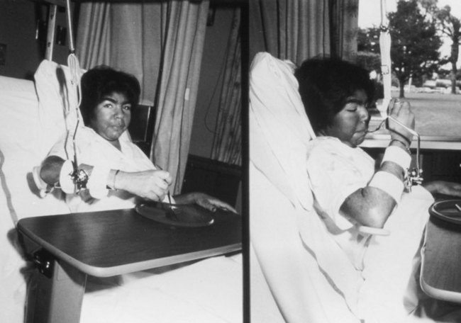

Adjustment of Suspension Arm Devices
Straps: The strap that connects the suspension rod to the limb directly or by the horizontal bar (adjustable balance bar) or forearm support attachment may be adjusted for length. This provides elevation control for the entire limb or for the wrist and elbow separately when separate supports are provided. Adjustments for height relative to the work surface or to the face are similar to adjustments discussed in the later section on MAS.
Height: The suspension rod can be adjusted on the wheelchair suspension mount. The higher the suspension rod, the flatter is the arc of pendulum swing when the arm is in motion. Usually the rod is kept as high as possible while allowing the wheelchair to pass through doorways. Lowering the rod shortens the pendulum arc and causes the upper limb to move uphill at each extreme of the arc. Lowering the suspension rod can add undesirable resistance to a group of muscles during occupational performance.
Rotation: The shoulder can be placed in horizontal abduction and external rotation as the suspension rod is rotated outward, or in horizontal adduction and internal rotation if the suspension rod is rotated inward. This gives a mechanical advantage to those muscles held in shortened range and offers resistance to opposing muscles.4,19
Springs: Springs of various tensions may be inserted into the straps supporting the upper limb. In early muscle re-education, these springs allow the very weak client to produce and visualize some slight bouncing movement while upright by contracting available muscles—a motion that is not as easily possible with straps alone.
Horizontal Bar: Moving the strap on the holes on the horizontal bar (also called an adjustable balance bar, made by JAECO16) will position the elbow in greater or lesser degrees of flexion. The bar is often positioned for the comfort of the client; if edema is present, the hand is held higher than the elbow.
Forearm Support: Forearm support (manufactured by JAECO16) is the same that is used in the MAS. However, this forearm support has a vertical metal suspension rod attached to the rocker arm (also called offset swivel). The rocker arm can be moved on the forearm support, which permits greater directional assistance for vertical motion, up or down, depending on the client’s specific weakness in shoulder rotator or elbow musculature.
Reclining Suspension Mount: For all suspension devices, the suspension rod may be supported by a reclining suspension mount that permits the suspension to be perpendicular to the floor when the client is reclined in the wheelchair (see Figure 30-42).
Training in the Use of Suspension Arm Devices
Suspension arm supports can be used as training for or as an interim device before the MAS is used. Training can include exercises for the shoulder and elbow, including scapular protraction and adduction, shoulder flexion and extension, elbow flexion and extension, and shoulder internal and external rotation (especially with use of the forearm support and the rocker arm). Because the forearm support is easily attached to over-bed frames, occupational performance can be practiced using a table surface and any distal orthoses and adapted equipment that are needed7 before the client is able to be upright in a wheelchair.
OT Practice Note
Clients should recognize early in rehabilitation that they can manage an occupation of choice so that feelings of helplessness and hopelessness are not overwhelming.
Threaded Case Study
Manny, Part 2
When Manny first was admitted to rehabilitation, he was hopeful that he would recover from his spinal cord injury with no physical loss. It could be difficult, at this time, to introduce the idea of arm supports, which may appear to him as taking away his hope for recovery. Manny was educated by the OT to understand that use of this equipment would facilitate any recovery that may be possible. He was confined to bed for the first few days in rehabilitation, but he was medically cleared to use his upper extremities and to partially sit in bed. Use of the suspension arm support in bed would allow him to participate in some occupation that he wishes to do and that is not overly challenging. Manny decided that turning pages would be a good initial occupation because he likes to read, and because it would be a first step toward doing what he would need to do in his law practice. A suspension arm support was attached to overhead bars attached to his bed. An over-bed tray with a book rack held his book. A universal cuff with the eraser end of a pencil attached and a wrist support enabled Manny to turn pages with his suspension arm support and with his bed raised for partial sitting. This allowed Manny to start thinking early in his rehabilitation about occupations he could manage with arm supports, in addition to working on the performance skill of strengthening upper extremity musculature, which otherwise would be underused while Manny was lying in bed.
Mobile Arm Supports
Mobile arm supports are mechanical devices that support the weight of the arm and provide assistance to shoulder and elbow motions through a linkage of ball-bearing joints. They are used for persons with weakness of the shoulder and elbow that affects their ability to position the hand. Mobile arm supports are or have been known by other names. Among these are MAS, ball-bearing feeder, ball-bearing arm support, balanced forearm orthosis (BFO), and arm positioner.
The MAS typically used (Figure 30-43) has not changed significantly in design since 1952.5 Earlier prototypes were reported as long ago as 1936, when a client at the Georgia Warm Springs Foundation was given a Barker feeder, a device that was bolted to the lapboard of a wheelchair that required shoulder depression to bring the hands toward the head. Several other models were subsequently reported in the literature, until the 1952 segmented arm feeder was designed; this had close similarities to devices used today.5,27
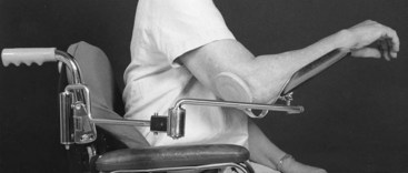
FIGURE 30-43 Traditional mobile arm support set up on a wheelchair. (Courtesy Paul Weinreich, Rancho Los Amigos National Rehabilitation Center.)
MASs have increased upper extremity function for persons with severe arm paralysis caused by conditions such as cervical spinal cord injury, muscular dystrophy, Guillain-Barré syndrome, amyotrophic lateral sclerosis, poliomyelitis, and polymyositis.13,30 The MAS has also been used for pain relief in the upper arm during occupational performance for clients with arthritis and other painful conditions.
How Mobile Arm Supports Work
MASs compensate for proximal weakness in the upper extremities in three ways: (1) they provide arm motion, which allows for active ROM in the shoulder and elbow; (2) they allow weak muscles that cannot perform movement to allow for occupational performance; and (3) they enable hand placement in a variety of positions for occupational performance.
Mobile arm supports can be used for occupational performance (i.e., allowing the weak arm to perform tabletop and hand-to-face occupations, which otherwise are impossible or difficult) and for therapeutic exercises (i.e., improving ROM, strength, and endurance). These devices may be temporary or permanent.24
The mechanical principles of mobile arm supports are threefold: the MAS (1) uses gravity to assist weak muscles, (2) supports a weak arm to reduce the load on weak muscles, and (3) reduces friction by using ball-bearing joints.24
Criteria for Use24,32
Occupational Performance Need: The person must have a need to perform specific occupations that cannot otherwise be accomplished because of weak shoulder and elbow musculature.
Adequate Source of Power: The source of power can be the muscles of the neck, trunk, shoulder, shoulder girdle, and elbow.
Adequate Motor Control: The person must be able to contract and relax functioning muscles. People with such conditions as cerebral palsy or significant elbow flexor tone usually are not good candidates for use of mobile arm supports.
Sufficient Range of Motion: The preferred ROM for joints to use the MAS well consists of shoulder flexion and abduction of 90 degrees, shoulder external rotation of 30 degrees, normal shoulder internal rotation and elbow flexion, forearm pronation of 80 degrees, and hip flexion of 100 degrees.
Stable Trunk Positioning: An upright sitting posture is ideal. Good head and neck positioning is important.
Client Motivation: The client must want to use the device and must have sufficient motivation for training to use it proficiently.
Supportive Environment: Generally, individuals who use this device cannot put it on themselves and will need help.
Manny meets all of the criteria listed here. He has occupations of interest that can be accomplished through the use of a mobile arm support. He has adequate performance skills (strength, ROM, stable sitting posture, and motor control) that will allow him to use the MAS. He is highly motivated to return to his law practice and has a very supportive wife. The support of the law firm is somewhat questionable, because staff members wonder how Manny will be able to manage all aspects of the work of an attorney in their offices.
Adjustment of Mobile Arm Supports
Adjustment of MASs generally requires postgraduate hands-on training. However, acquiring some knowledge of adjustment will give the reader a greater appreciation for the need to obtain additional training to learn how to make fine adjustments. One study has shown that even when the MAS is not adjusted correctly, a person with sufficient muscle power can overcome the lack of fine adjustment.31 This does not negate the need for therapists to be trained to ensure the best possible adjustment and mechanical advantage for clients using the MAS.
Even with hands-on training, additional parts beyond the basic pieces can enhance the effectiveness of the device. The training needed to use these additional parts comes with practice, experience, and consultation with therapists familiar with the use of special parts.
Adjustment of Basic Parts: See Figure 30-44.
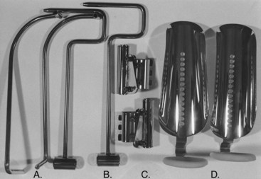
FIGURE 30-44 Parts of traditional mobile arm support. A, Distal arms, right and left. B, Proximal arms. C, Semireclining mounts, right and left. D, Forearm supports.
Forearm Support: Forearm support is initially attained by bending the dial to accommodate the left or right elbow (Figure 30-44, D).
Rocker Arm: The rocker arm is attached to the support. The standard rocker arm is attached to the first and third holes closest to the elbow.
Semireclining Mount, Proximal Arm, Distal Arm, and Forearm Support: The mount (Figure 30-44, C) is attached to the left or right wheelchair upright, the proximal arm (Figure 30-44, B) is placed in the mount, the distal arm (Figure 30-44, A) is placed in the proximal arm, and the forearm support is placed in the distal arm.
Balancing the Mobile Arm Support at Neutral: The mount is adjusted so that the ball bearings are parallel to the floor.
Checking Mount Height: The client is placed in the MAS, and the therapist passively moves the hand to the mouth. If the shoulder is elevated or depressed, the height of the mount should be adjusted.
Assessing Forearm Support for Fit and Adaptations: The support is observed for forearm comfort and allowance of wrist flexion (if the client has active motion). Measurements are taken to have the support cut if necessary to prevent discomfort and nonconformity with the size and shape of the forearm.
Adjusting for Horizontal Motion: The mount is rolled to assist horizontal abduction or adduction. The pitch of the mount or the distal bearing is adjusted to achieve maximum horizontal motion in front of the client.
Adjusting for Vertical Motion: The rocker arm is moved on the mount if up or down motion is difficult.
Checking Fit During Occupational Performance: Further adjustments may be needed with the weight of objects in the hand.24
Training
Training includes practice in all occupations that interest the client and that need to be performed. Any of these occupations may require various adjustments until the final settings are achieved. If strength or ROM increases during the training period, further adjustments may be needed. Adapted equipment can be used in conjunction with the MAS. A wrist-hand orthosis may be required or adjusted for use with the MAS.24
Follow-up with clients is indicated, especially for a growing child. MASs can result from adjustments over time. The questions in Box 30-1 are modified from an MAS appraisal form that was developed during the polio era at Rancho Los Amigos National Rehabilitation Center.23 It can serve as a useful tool for checking the adequacy of fit of the MAS when the client returns to the clinic for follow-up visits.
Threaded Case Study
Manny, Part 3
After 2 weeks in rehabilitation, Manny was able to sit in a wheelchair 2 to 3 hours daily. He was given a motorized wheelchair, which he operated with a chin switch for mobility and for reclining the wheelchair to obtain pressure relief every hour while he was awake. He was still unable to participate in any of the most important occupations needed to return to his law practice.
He was given a traditional MAS and a lapboard on his wheelchair. He continued to turn pages, now with an MAS and his wrist-hand orthosis. With the MAS, his wrist-hand orthosis, and a computer, he began to compose written communications, sending e-mails to his wife, his child, coworkers, and friends. Occupational performance activities that require hand-to-mouth skills are more complex than tabletop activities, so these occupations were introduced more slowly by working on reaching higher and higher in vertical motions. Games, such as building pyramids with blocks, were used until Manny could reach his mouth with his hand; then eating activities were introduced, using a wrist-hand orthosis that could hold an adapted spoon and fork.
Although with Manny’s available upper extremity strength, it was questionable whether he could use his MAS for driving his motorized wheelchair, Manny wanted to do so. He did not like the image of a chin switch to drive his wheelchair. He practiced using the MAS to drive his wheelchair until this task was accomplished. With practice, he also could efficiently operate his computer, turn pages, manage a speakerphone, and feed himself simple meals. He needed assistance in removing his MAS when he reclined, so that pressure on his ischium was relieved.
When he was discharged, Manny returned to the outpatient OT clinic, where a plan was made to have the OT and Manny visit the law office to determine how he could perform occupations needed in the law office. In addition to equipment obtained as an inpatient, it was recommended that Manny could benefit from a large round desk that acted as a turntable operated electrically. With this turntable, he could access his special phone, computer, and reading matter. Also, Manny learned that through his oratory skills, he could project a positive image that would be perceived by members of the public arriving to his office. This visit and the implementation of equipment recommendations resulted in Manny’s return to his law practice 2 months after discharge.
Special Parts of the Mobile Arm Support
Commonly used special parts include the outside rocker arm assembly (also known as an offset swivel) (Figure 30-45, A) and the elevating proximal arm (Figure 30-45, B).16 The outside rocker assembly has a ball-bearing joint that allows greater freedom in vertical motion. The elevating proximal arm is useful for the person who has deltoid muscles that are between fair (F or 3) and poor (P or 2). The client initiates the elevating motion, and rubber band assists allow the client to flex and abduct the humerus to a higher level.
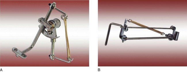
FIGURE 30-45 A, Offset swivel with up and down stops and humeral rotation assist (outside rocker arm with rubber band assist). B, Elevating proximal arm. (Courtesy JAECO Orthopedic, Inc., Hot Springs, Ark.)
Many other useful, but not commonly used, special parts are commercially available for clients with special problems. Understanding the use and adjustment of these special parts generally requires training.24 With the advent of new designs for wheelchairs, it sometimes becomes necessary to adapt the MAS bracket for attachment to these newer chairs. Wheelchair manufacturers can assist by providing solutions to problems; some centers have developed common solutions.24
Current Development and Future Research
The traditional MAS has been used effectively for longer than 50 years. However, until recently, little evidence could be found in the literature to show advancements in the design of commercially available MASs that would expand their use to those who have upper extremity weakness.
An example of development during this period was an attempt by engineers approximately 40 years ago to provide a powered arm for persons who have minimal strength in the upper extremities. The Rancho Electric Arm was developed to meet the needs of those who are too weak to use a conventional MAS.29 It requires that clients use their tongue to operate seven tiny toggle switches in complex patterns to achieve motions at the joints of the arm and hand.18
In 1995 the Rehabilitation Engineering Program at Rancho Los Amigos National Medical Center received a National Institute on Disability and Rehabilitation Research (NIDRR) grant to design, develop, and test a new MAS.21 During 12 years of grants related to this new design (NIDRR#H133E003001, #H133E020732), the project developed an entirely new MAS system. It incorporated a multilink arm that has a low profile and a high-tech appearance (Figures 30-46 and 30-47, A). The new mount fits many current wheelchairs, has simple, intuitive adjustability without tools, and locks in position to retain adjustments (Figure 30-47, B). The forearm support includes a slide-lock to adjust its pivot point (Figure 30-47, C). The new JAECO/Rancho Multilink Arm (MAS) was transferred to a manufacturer (JAECO) that made it available commercially in 2003.21 In addition, mount adapters (an example is shown in Figure 30-47, D) provided by this manufacturer enable the new JAECO/Rancho MAS mount or the traditional MAS bracket to attach to the expanding variety of wheelchairs that have exploded onto the market.21 Also, a manual height adjuster has been made available, if needed, to allow for mount height changes from desk to mouth level occupational performance.26 An elevation assist for the Multilink has been made available by JAECO for the Multilink Arm. This part functions similarly to the elevating proximal arm of the traditional MAS.17
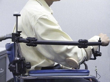
FIGURE 30-46 New multilink mobile arm support. (From Rancho Los Amigos National Rehabilitation Center, Rehabilitation Engineering Center, Downey, Calif.)
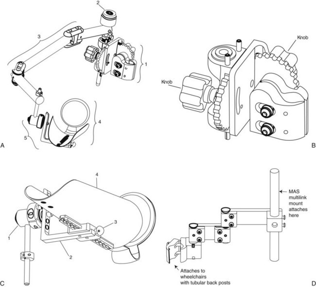
FIGURE 30-47 A, JAECO/Rancho Multilink Mobile Arm Support. (1) MAS mount. (2) Proximal shaft with bubble level. (3) Multilink. (4) Forearm support with elbow dial. (5) Offset swivel with adjustable slide. B, JAECO/Rancho Multilink Mobile Arm Support mount. Two knobs control adjustment without use of tools. C, JAECO/Rancho Multilink Mobile Arm Support offset swivel with adjustable slide. (1) Offset swivel with (2) adjustable slide. (3) Spring-loaded pull-out knob to adjust position on the forearm support (4). D, JAECO Mount Adapter MR-10 enables the JAECO/Rancho mount to attach to wheelchairs with tubular back posts. (Courtesy JAECO Orthopedic, Inc., Hot Springs, Ark.)
To further identify some of the issues related to use of the traditional MAS during the grant periods, a survey was conducted of 17 OTs, each with an average of 15 years’ experience working with clients with spinal cord injury in various parts of the United States and Canada.3,31 One of the questions asked of respondents was to identify problems with the traditional MAS. The following is a partial list of some of the more highly ranked limitations of the MAS as determined by these therapists:
1. It is difficult to adjust the MAS, especially for weak clients.
2. Parts extend too far out from the wheelchair, which limits the client’s ability to go through doorways.
3. The MAS sometimes hits the table, wheelchair armrest, or joystick control when the client is moving the arm.
4. The MAS cannot be mounted or easily mounted on all wheelchairs.
5. Adjustments have to be made with changing activities such as driving and eating.
6. The MAS does not easily accommodate the client who needs to recline routinely.
The first three problems listed here have been addressed with the now commercially available JAECO/Rancho Multilink Mobile Arm Support: (1) adjustment is easier, (2) the device is narrower to allow entrance through doorways, and (3) it is easier to use the device when moving horizontally to bypass armrest, joystick, or table edge.25 For problems (4) and (5) in the list, the new mount adapters and the manual height adjuster provide solutions. Problem (6) has not yet been solved.
Besides the JAECO/Rancho Multilink MAS, another MAS, the Wilmington Robotic Exoskeleton (WREX), has recently been developed in the United States, especially for people with proximal arm weakness who have hand function, primarily those with neuromuscular diseases such as spinal muscular atrophy.10,22 This device is now commercially available.
Threaded Case Study
Manny, Part 4
With Manny’s performance skills, he was at first able to benefit from using suspension arm supports in bed, wearing a wrist-hand orthosis, and using adapted equipment to read and turn pages. When he was sitting up in a motorized wheelchair, he was given an MAS, with which he continued to use his wrist-hand orthosis along with other adapted equipment to perform the occupations he needed to perform to return to work in his law firm. Because of his early expectation that he would recover from his spinal cord injury, it was important for the OT to acknowledge Manny’s hopes, while discussing with him what was available for him to do to work on returning to work soon, using the equipment he would need to do so.
The series of interventions that the OT used included the following: (1) worked on occupations that Manny could perform while in bed, (2) applied MASs to his motorized wheelchair and found adaptive equipment that he could hold with his wrist-hand orthosis, (3) provided games and other activities that would strengthen his upper extremity musculature to perform vertical motions in his MAS so that he could eventually feed himself, (4) practiced all occupations needed in his job—helped to find a phone that he could use with his MAS and wrist-hand orthosis, found a joystick to drive his wheelchair that was comfortable to use with an MAS and wrist-hand orthosis, and found other adaptive equipment that was reliable for him to use on the job, (5) located and provided information on community resources to help Manny manage in his home community, including sources for adaptive equipment and adaptations that would allow a vehicle to carry a motorized wheelchair, and (6) made a worksite visit with Manny when he was ready to return to work, to ensure that his equipment works in the office and to talk with staff about assistance that he may need.
Summary
Section 1 of this chapter introduced the basic concepts of splint design and problem solving that must precede fabrication of a splint. Anatomy and biomechanics of the hand and types of grasp and prehension were reviewed. Splint classification and the purposes of splinting were described. Section 2 presented a variety of splinting materials and explained their appropriate uses for different types of splints. Principles of safe and effective splinting and basic fabrication techniques were also described. The OT must bring to the splinting process knowledge of anatomy and biomechanics, skills in assessing function, and the ability to determine the optimal intervention for each client.
Clients of all ages with a variety of diagnoses and various patterns of weakness have been known to have the same MAS for at least 10 years. When fitted correctly, the MAS enhances occupational performance and can facilitate remediation of performance skills. For some clients, the device is useful for life. For other clients, the mobile support is a temporary device that allows function and enables exercise until the musculature is strong enough that they can engage in occupations without the device.
Over the few years since the JAECO/Rancho Multilink MAS first became available, fitting and adjustments have been streamlined, the device has become less conspicuous and more aesthetically appealing to clients, and adjustments have been simplified for therapists working with patients without complex or profound weakness. It remains unknown whether these new devices will supplant the traditional MAS, which has been adjusted for profoundly weak patients by those with expert knowledge and skill. The JAECO manufacturer has found that more customers are purchasing supports with newer designs (e.g., Multilink, WREX) than the traditional mobile arm support.10 With current advancements in design, it is hoped that more clients who can benefit will be fitted with an MAS to engage in occupations and to fully participate in the home and community to which they belong.
1. Describe the role of the OT in the splint-making process.
2. What is wrist tenodesis and how can it be used functionally?
3. Describe the axis of motion of forearm rotation, and discuss how it affects the fit of a splint.
4. Name the three major nerves that supply the hand and describe their sensory innervation patterns.
5. Why is tip prehension considered to be a dynamic rather than static prehension pattern?
6. What is the one grasp pattern that does not include the thumb?
7. Define the terms friction, torque, and stress.
8. How is shear stress created and how can it best be avoided?
9. Why do translational forces minimize the effectiveness of a splint?
10. Describe the difference between a dynamic and a static splint.
11. How may a splint pattern vary if it is to be fitted on the dorsum of the hand, as compared with the volar surface?
12. How does the amount of drape in a low-temperature thermoplastic material affect the making of a splint?
13. What is the recommended type of material for small finger splints? Why?
14. What is the recommended type of material for large elbow and lower extremity splints? Why?
15. What is the importance of straps on a single-surface splint?
16. What are the purposes of suspension arm devices and MASs?
17. Where are suspension arm devices attached?
18. What are the limitations of suspension arm devices?
19. What is the difference between a suspension arm sling and a suspension arm support?
20. Who are good candidates for suspension arm devices?
21. How are suspension arm devices adjusted?
22. Approximately how long have traditional mobile arm supports been used?
23. Name the parts of the MAS.
24. What are the benefits of the MAS?
26. What are the criteria necessary to use the MAS?
27. How is the MAS adjusted for each client?
28. What is the advantage of the JAECO/Rancho Multilink Mobile Arm Support?
References
1. American Society of Hand Therapists. Splint classification system. Chicago: The Society; 1992.
2. Anderson KN, Anderson LE, Glanze WD, eds. Mosby’s medical, nursing, and allied health dictionary, ed 4, St Louis: Mosby, 1994.
3. Atkins, MS, Baumgarten, JM, Yasuda, YL, et al. Mobile arm supports: evidence-based benefits and criteria for use. J Spinal Cord Med. 2008;31:388–393.
4. Bennett, RL. Orthotics for function. I. Prescription. Phys Ther Rev. 1956;36:1.
5. Bennett, RL. The evolution of the Georgia Warm Springs Foundation Feeder. Artif Limb. 1966;10:5.
6. Bennett, RL, Stephens, HR. Care of severely paralyzed upper extremities. JAMA. 1952;149:105.
7. Bonutti, PM, Windau, JE, Ables, BA, et al, Static progressive stretch to reestablish elbow range of motion. Clin Orthop Relat Res, 303, 1994:128.
8. Brand, PW, Hollister, A. Clinical mechanics of the hand, ed 3. St Louis: Mosby; 1999.
9. Colditz, J. Dynamic splinting of the stiff hand. In Hunter J, Schneider L, Mackin E, et al, eds.: Rehabilitation of the hand: surgery and therapy, ed 3, St Louis: Mosby, 1990.
10. Conry M: Personal communication, April 2010.
11. Fess, EE, Gettle, KS, Philips, CA, et al. Hand and upper extremity splinting: principles and methods, ed 3. St Louis: Mosby; 2005.
12. Flatt, AE. Care of the arthritic hand. St Louis: Mosby; 1983.
13. Haworth, R, Dunscombe, S, Nichols, PJR. Mobile arm supports: an evaluation. Rheumatol Rehabil. 1978;17:240.
14. Hollister, A, Giurintano, D. How joints move. In Brand PW, Hollister A, eds.: Clinical mechanics of the hand, ed 3, St Louis: Mosby, 1999.
15. Jacobs ML and Austin NM: Splinting the hand and upper extremity: principles and process, Baltimore, Lippincott Williams & Wilkins, 2003.
16. JAECO Orthopedic Inc. Catalog, Hot Springs, Ark (undated).
17. JAECO Orthopedic, Inc.: Set-up instructions for multilink mobile arm support, Hot Springs, Ark, May 27, 2008, JAECO.
18. Landsberger, SE. Keep moving: RERC on technologies to enhance mobility and function for individuals with spinal cord injury NIDRR application. Downey, Calif: Los Amigos Research and Education Institute, Rancho Los Amigos National Rehabilitation Center; 2002.
19. Long, C. Upper limb bracing. In: Licht S, ed. Orthotics etcetera. Baltimore, Md: Waverly Press, 1966.
20. McCollough, N, Sarrafian, S. Biomechanical analysis system. In: Atlas of orthotics, biomechanical principles and application. St Louis: Mosby; 1975.
21. McNeal, D, et al. Rehabilitation engineering program: annual report, RERC on technology for children. Downey, Calif: Los Amigos Research and Education Institute, Rancho Los Amigos National Rehabilitation Center; 2000.
22. Rahman, T, Sample, W, Seliktar, R, et al. Design and testing of a functional arm orthosis in patients with neuromuscular diseases. EEE, Transactions on neural systems and rehabilitation engineering. 18, June 2007.
23. (unpublished). Mobile arm support appraisal, Downey, Calif, Rancho Los Amigos Medical Center, Occupational Therapy Department, 1969.
24. Mobile arm support workshop manual. Downey, Calif: Rancho Los Amigos National Rehabilitation Center, Occupational Therapy Department, 1998.
25. Rehabilitation Engineering Program. Quarterly report. Keep moving: RERC on technologies to enhance mobility and function for individuals with spinal cord injury. Downey, Calif: Los Amigos Research and Education Institute, Rancho Los Amigos National Rehabilitation Center; 2004.
26. Rehabilitation Engineering Program: 2007 reporting to IRB, the active mobile arm support (1839-03), and 2007-2008 SCI RERC report (new generation mobile arm supports for better hands-on activity, 1940-2), Downey, Calif., 2007, Los Amigos Research and Education Institute.
27. Snelson, R, Conry, J. Recent advancements in functional arm bracing correlated with orthopedic surgery for the severely paralyzed upper extremity. Orthop Prosthet Appliance J. 41, 1958.
28. Strickland, JW. Anatomy and kinesiology of the hand. In Fess EE, Gettle KS, Philips CA, et al, eds.: Hand and upper extremity splinting: principles and methods, ed 3, St Louis: Mosby, 2005.
29. Trombly, CA, Radomski, MV. Occupational therapy for physical dysfunction, ed 5. Baltimore, Md: Lippincott Williams & Wilkins; 2002.
30. Wilson, DJ, McKenzie, MW, Barber, LM. Spinal cord injury: a treatment guide for occupational therapists, rev ed. Thorofare, NJ: Slack; 1984.
31. Yasuda, YL. Unpublished document for NIDRR Grant: Keep moving: RERC on technologies to enhance mobility and function for individuals with spinal cord injury. Downey, Calif: Los Amigos Research and Education Institute, Rancho Los Amigos National Rehabilitation Center; 2004.
32. Yasuda, YL, Bowman, K, Hsu, JD. Mobile arm supports: criteria for successful use in muscle disease clients. Arch Phys Med Rehabil. 1986;67:253.