Chapter 32 Orthovoltage generators and linear accelerators
Chapter contents
32.1 Aim
The aim of this chapter is to review the main differences between diagnostic X-ray generators and the orthovolvoltage generator. It will also present an overview of the linear accelerator.
32.2 Introduction
X-rays at energies of up to 300 kV have been used to treat benign and malignant conditions since the early twentieth century. Historically this has been in two categories:
1. Superficial therapy using energies of up to 150 kV with beam filtration of 1–8-mm aluminium equivalent material at a focus to skin distance (FSD) of 10–30 cm.
2. Orthovoltage or ‘deep’ therapy with energies of 150–500 kV with 0.5–3-mm copper filtration at a 50-cm FSD.
Superficial units are rarely found in clinical use today, as many of the conditions they were used to treat are no longer common and other more efficient methods of treatment have been developed, many of which do not use ionizing radiation. These units are unable to deliver sufficient dose to areas of significant separation; they produce a high surface dose and a significant amount of scattered radiation is produced outside the beam as a result of Compton scatter. Orthovoltage units, with their increased higher energies and filtration, deliver less surface dose. Although the beam still produces large amounts of Compton scatter, the differential absorption of radiation by tissues of higher atomic number, such as bone, makes orthovoltage treatment suitable for use on patients with metastatic bone deposits and some primary bone lesions.
32.3 The orthovoltage unit
There are a number of similarities and differences between these units and the general diagnostic unit. The orthovoltage unit uses a stationary anode X-ray tube, unlike the rotating anode used in diagnostic radiography. The circuit of a high voltage generator is similar to that of modern microprocessor-controlled medium-frequency diagnostic generators (see Ch. 28). However, the control panel differs in that a number of distinct stages must be followed in sequence before exposure can be initiated; these include the ability to select the additional filtration used – this automatically sets the kV and mA available. The radiographer must then select the dose to be delivered and the exposure time. This determines the setting of the back-up timer, which will terminate the exposure if the elapsed time exceeds the set time by 10%. Other differences are the beam filtration and the way in which the beam is collimated.
32.3.1 The X-ray tube
Unlike the rotating anode design found in diagnostic units, the orthovoltage unit uses a hooded stationary anode (see Fig. 32.1). This is likely to have an insert with a metal–ceramic envelope, which overcomes the common cause of tube failure, which in these units is usually the breakdown of the glass envelope around the insert. As can be seen, the target is surrounded by shielding apart from two ports: the first is in line with the electron beam from the cathode, and the second, covered by a beryllium window, is at 90° to this axis and in line with the tube exit port. This permits the beam of useful radiation to leave the anode and tube. The hood serves two functions: i) it absorbs secondary electrons produced by electron interaction with the target; and ii) it attenuates unwanted radiation, reducing the thickness of the lead required in the tube housing, thus reducing weight of the tube assembly. Note that the anode, which loses heat through conduction to the oil surrounding the insert, has, in addition to a large cross-sectional area, channels in it through which oil is circulated, thus improving the cooling process.
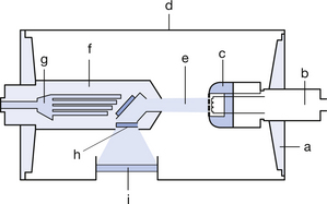
Figure 32.1 Simplified diagram of an orthovoltage metal–ceramic X-ray tube insert. a, ceramic insulate support; b, cathode assembly; c, cathode block and filament; d, metal envelope; e, electron/radiation beam; f, hooded anode; g, oil coolant channels in anode; h, beryllium window; i, insert exit port.
32.3.2 Beam filtration
As with diagnostic X-ray tubes, the orthovoltage tube has both the inherent filtration that attenuates the beam due to the components of the tube and additional filtration produced by filters placed in the beam path after it has left the tube. In diagnostic units, the filtration, which serves to ‘harden’ the beam by removing low-energy radiation from the beam, is in the form of a thickness of an aluminium-equivalent material. With the orthovoltage tube, this filtration can be changed to suit the energy spectrum used to treat the patient. At lower energies, the filters are usually of a single material – aluminium, copper or tin. At higher energies, a composite filter such as the Thoreaeus filter, made of tin, copper and aluminium, is used. With these composite filters, it is important that the material of the higher atomic number is placed near the tube port. The function of the lower atomic number material is to remove the characteristic radiation produced by the filter material of higher atomic number.
32.3.3 Beam collimation
Collimation in the diagnostic unit is provided by the adjustable diaphragms in the form of the light beam diaphragm. The orthovoltage unit uses interchangeable cones or applicators of standard design. These are usually square or circular in shape and produce a beam field of up to 22 cm2. The applicators are attached to the tube housing by a large lead plate with an aperture that determines the field size of the applicator. Specially shaped applicators are often used for specific treatment areas, e.g. the canthus of the eye.
32.4 The linear accelerator
32.4.1 Introduction to the linear accelerator
Linear electron accelerators, or LINACs as they are commonly known, accelerate electrons in a straight path and differ from the cyclotron (see Ch. 37), in which electrons follow a circular path. They have been in used in radiotherapy since the 1950s to treat patients with malignant and benign disease. Since their introduction, they have virtually replaced earlier treatment systems such as cobalt units in the UK. The increasing complexity of treatment methods and improvements in technology have seen the LINAC develop from a relatively simple fixed-energy output unit to units with dual and multiple megavoltage output energies of up to 5 MeV, which are capable in some instances of techniques such as conformational therapy treatment methods. Improvements in electronics have resulted in increased unit reliability and stability of output. This is an important factor in radiotherapy treatment.
32.4.2 Construction of a typical linear accelerator and its principal components
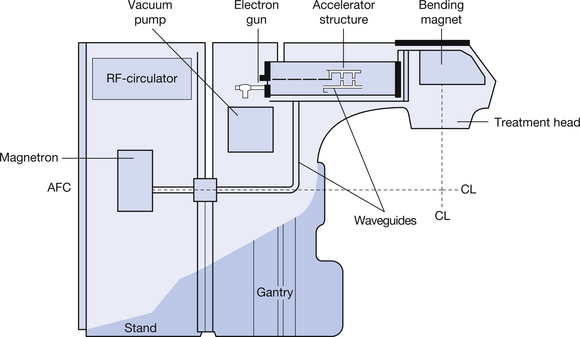
The construction of a typical LINAC and its principal components is shown in simplified form in Figure 32.2. As can be seen from the figure, the linear accelerator can be divided into two large structures – a floor-mounted stand and a motor-driven gantry which rotates about the treatment isocentre. These components are discussed individually in the following sections.
32.4.3 The magnetron
As can be seen from Figure 32.3, the is an evacuated cylindrical structure, consisting of a central hollow, indirectly heated, oxide-coated cathode and surrounded by a copper anode containing a number of equidistant cavities that communicate with the space surrounding the cathode. The entire structure is enclosed in a magnetic field running parallel to the long axis of the magnetron. Both anode and cathode are supplied by a pulsed direct current supply from the modulator. The voltage of this supply is selected so that the electron cloud emitted by the cathode forms a rotating field with a number of spoke-like projections. As the ‘spokes’ pass over the entry to the anode cavities, they lose about 60% of their energy, inducing them to resonate at a radiofrequency, rather in the same way that a musical note is produced by a flute when a musician blows over it.
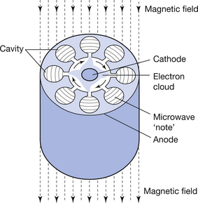
Figure 32.3 Section through a magnetron showing arrangement of anode, cavities, rotating electron field and electron field produced.
The resonance, at a frequency of 3000 MHz, corresponds to a wavelength of 10 cm. This results in the production of microwaves that are detected and transmitted into a waveguide. Stability of output is maintained by an automatic frequency control (AFC) which adjusts the size of the resonant cavity to maintain this frequency with an accuracy of ±20 kHz. The pulsed input means that, although the device operates at an average output of 2 kW, it has a peak output of 2–5 MW.
32.4.4 The waveguides and radiofrequency circulator
Two types of waveguide are found in a linear accelerator: the first are simple hollow tubes that carry the radiofrequency waves from the magnetron to the accelerator section waveguides (at these frequencies, the high impedance of solid conductors would result in significant power losses due to their impedance). The waveguides are sealed at both ends by ceramic discs that are transparent to microwave radiation and the first type of waveguide is filled with sulphur hexafluoride to improve its power-handling capabilities. A radiofrequency circulator is situated between the magnetron and the waveguide; its function is to act as a one-way valve permitting the radiofrequency radiation to pass into the waveguide, but preventing any from passing back into the magnetron, which would be damaged if this occurred. The accelerator waveguide is evacuated and differs in structure and purpose. This will be discussed in more detail in Section 32.4.5.
32.4.5 The accelerating waveguide and accelerator
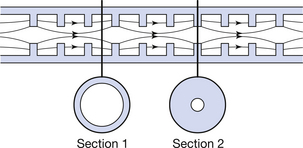
The accelerating waveguide and accelerator are situated in the gantry of the LINAC. The waveguide uses the radiofrequency wave to accelerate electrons to very high velocities. The principle underlying this process is that an electrical field exerts a force on a charged particle placed in the field. It follows that, for the force to continue to act on the particle, it must move with it. The waveguide is divided into a buncher and a relativistic or accelerating section: the latter forms about two-thirds of the total length of the waveguide. The main difference between the two sections is that the washer-like annular inserts (shown in Fig. 32.4) are closer together in the buncher section. The electrostatic fields in the buncher section slow the passage of the radiofrequency wave to approximately 0.4 C. As already mentioned, this waveguide is evacuated. It is also a resonant structure, which brings the ‘injected’ electrons into phase with one another. The accelerator is surrounded by a water jacket through which tempered cooling water flows to minimize the thermal contraction and expansion of the guide, which can change its resonance. An electron gun is attached to the buncher section and this injects electrons into the guide in pulses under the control of the modulator, in synchronization with the radiofrequency wave. Typically, only about one-third of the electrons are captured into the optimum part of the radiofrequency wave; however, because of the sinusoidal shape of the wave, the electrons, which are in non-optimal locations, will experience different degrees of acceleration and will decelerate and fall back until they are at the crest of the following wave. On reaching the accelerator section, the electrons gain velocity, reaching speeds of approximately 0.9 C. Because ‘like’ charges repel one another, the electron beam tends to diverge. This is countered by steering coils positioned externally along the length of the cooling jacket that produce lines of magnetic force running parallel to the long axis of the guide. Focusing coils at the entrance and exit of the waveguide carry out a similar function and ensure that the electron beam is centred to the centre of the guide and target.
32.4.6 The bending magnet and treatment head
The electron beam produced in the accelerator is travelling in a horizontal alignment with the gantry and must be deflected to assume an alignment, which is perpendicular to it. This process is carried out by the bending magnet, which deflects the electron beam through a 270° angle. The magnet is situated externally to the accelerator structure and, like the accelerating waveguide, is an evacuated structure. The radius of the bend depends on the velocity of the electrons; those with higher velocity are deflected in a turn with a larger radius, while lower velocity electrons are deflected in a turn of smaller radius, effectively focusing the beam to a small area at 270° to its original path. The effect is similar to focusing light waves to a point by an achromic lens. For this reason, the magnet is sometimes referred to as an achromic magnet. The effect shown in Figure 32.5 (see page 241) is to produce a small electron beam that yields treatment fields that have well-defined edges.
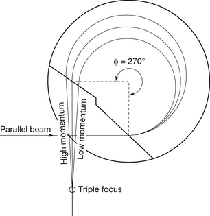
Figure 32.5 Diagram of a 270° bending magnet. Note that electrons of differing speeds are focused to a point on the target (see text for more detail).
The main components of the treatment head (which is set for electron therapy) are shown in Figure 32.6 (see page 241). The electron applicator is attached to an external mounting on the treatment head. If X-ray treatment is required, the scattering foil, which is designed to produce a ‘flat’ electron beam, is rotated out of the electron beam and is replaced by a thin tungsten transmission target and a bell-shaped flattening filter. In both instances, the radiation beam passes through a dual ionization chamber. This monitors beam intensity and is also used to terminate the exposure when the desired amount of radiation has been produced.
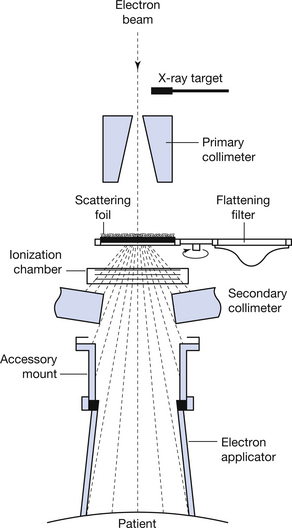
Figure 32.6 Treatment head set for electron therapy. For X-ray therapy, the scattering filter is rotated out of the beam and replaced by the transmission target and flattening filter.
In this chapter, you will have learnt the following:
• Why superficial therapy machines are no longer used for radiotherapy treatment (see Sect. 32.2).
• How the orthovoltage X-ray tube insert differs in design from a diagnostic insert (see Sect. 32.3.1).
• How the tube filtration differs between radiotherapy tubes and diagnostic tubes (see Sect. 32.3.2).
• Why waveguides are used in preference to solid conductors (see Sect. 32.4.4).
• The structures found in the treatment head of a linear accelerator (see Sect. 32.6).
Further reading
Bomford C.K., Kunkler I.H. Walter’s and Miller’s Textbook of Radiotherapy, second edn. Edinburgh: Churchill Livingstone, 2003. (Chapters 9 and 10)
Cherry P., Duxbury A. Practical Radiotherapy Physics and Equipment. London: Greenwich Medical Media, 1998. (Chapters 9 and 10)
Greene D., Williams P.C. Linear Accelerators for Radiation Therapy, second edn. Bristol: Institute of Physics, 1997.
Morris S. Radiotherapy Physics and Equipment. London: Churchill Livingstone, 2001. (Chapters 5 and 7)