Chapter 37 Radionuclide imaging
Chapter contents
37.1 Aim
The aim of this chapter is to introduce the reader to the basis of the technology used in radionuclide imaging. The information available on a nuclear medicine scan will be compared with the information available on other forms of medical imaging.
37.2 Basic concept of radionuclide imaging
The basic concept of radionuclide imaging involves a three-stage process:
37.3 Production of artificially produced radionuclides
There are three common ways of producing artificially produced radionuclides which are then used in radionuclide imaging. These are:
37.3.1 The nuclear reactor
The nuclear reactor (or pile) produces heat energy by controlled fission (see Sect. 19.9). The heat generated within the reactor raises the temperature of a coolant which in turn is used to heat water to produce steam. The steam can then drive very powerful electric generators. This is the basis of nuclear power stations.
A simplified diagram of such a reactor is shown in Figure 37.1 (see page 272). The controlled fission is produced by using the neutrons of fissile decay to produce further fission in other atoms. Thus, a sustained reaction can be set up where one neutron released during the fission of a nucleus will interact with another nucleus to produce fission of that nucleus with the release of further neutrons.
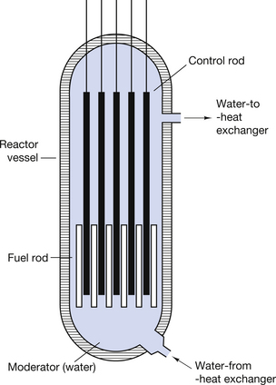
Nuclear reactors are important in radionuclide imaging in that they allow us to insert samples into the neutron flux within the reactor. This results in neutrons being inserted into nuclei to allow the manufacture of artificial radionuclides. An example of this is that stable molybdenum-98 can be made to absorb a neutron to produce the radionuclide molybdenum-99. The reaction may be shown using the equation below:
37.3.2 The technetium generator
It is not feasible to produce nuclei with very short half-lives at a remote site and then transport these to the hospital. Such radionuclides are produced at the hospital’s radiopharmacy either by the use of a technetium generator or by the use of a medical cyclotron.
The technetium generator used in nuclear medicine is an important example of the production of artificial radionuclides. As mentioned in Section 37.3.1, if molybdenum-98 is placed in a neutron stream, the nuclei of the molybdenum atoms can be made to absorb the neutrons to produce molybdenum-99. The capture of a neutron raises the energy of the resulting molybdenum-99 nuclei and each loses this energy by the prompt emission of a gamma-ray.
A molybdenum-99/alumina column is in the centre of the generator, as shown in Figure 37.2 (see page 272). The molybdenum-99 has a half-life of 67 hours and decays to form technetium-99m by β−-particle emission, as shown below:
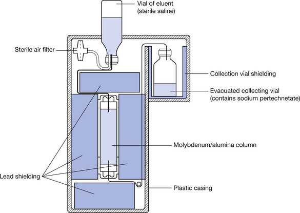
The  is eluted (or flushed) from the generator at regular intervals as sodium pertechnetate. This radionuclide, which is in liquid form, may be used for a number of radionuclide imaging situations. The
  decays to
  by the emission of a gamma-ray of energy 140 keV. The metastable radionuclide has a half-life of 6 hours. Clearly, after a period of time, the activity of the molybdenum-99, and hence its ability to produce technetium 99m, will be reduced and the technetium generator must have its molybdenum-99/alumina column replaced.
A number of other radionuclides used in nuclear medicine can be produced from stable materials when they are bombarded with particles but further discussion about their production is beyond the scope of this section
37.3.3 Production of radionuclides using a cyclotron
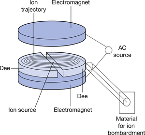
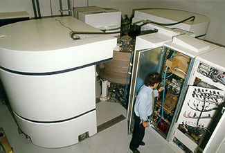
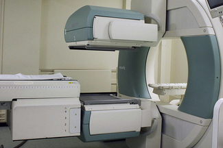
The type of cyclotron used in nuclear medicine to produce artificial radionuclides by the bombardment of stable substances will briefly be described. A simple diagram of such a device is shown (see Fig. 37.3) (see page 272). The cyclotron consists of an evacuated cylinder which has an ion source placed at its centre. Ions from this source are influenced by strong axial and radial magnetic fields. This causes acceleration of the ions in circular paths of increasing radius. This ion beam achieves significant velocity and can be made to interact with materials placed at the exit port of the cyclotron. This interaction causes nuclear changes in these materials and we can produce neutron-deficient nuclei (see Sect. 19.5.1) which are capable of positron emission. Such materials form the basis of the radiopharmaceuticals used in positron emission tomography (PET) scanning. Figure 37.4 (see page 272) shows a photograph of such a medical cyclotron.
37.4 Clinically useful radionuclides
Radionuclides are used to diagnose and to treat certain conditions. When they are used for diagnosis, they may be labelled (chemically linked) to a certain radiopharmaceutical, thus encouraging their uptake by specific body parts. The labelled radionuclide may then be injected into, or ingested by, the patient. Such diagnostic techniques in nuclear medicine have three main uses:
1. To provide numerical or graphical information on organ physiology, e.g. technetium-labelled diethylene triamine penta-acetic acid (DTPA) will give information on the rate of excretion of this radionuclide by the kidneys, thus giving information on renal function.
2. To produce an image of organ physiology on a gamma camera, e.g.  as pertechnetate may be injected into the patient to produce images of the skeletal physiology; this is for very useful early detection of metastatic spread into bone.
3. To produce information on organ physiology using PET scanning (see Ch. 40), e.g. brain scans using fluorodeoxyglucose can produce images of cerebral physiology indicating the levels of cerebral activity for specific tasks.
A list of the radioisotopes which are commonly used is given in Table 37.1 (see page 275).
Table 37.1 Radionuclides commonly used in medicine
| APPLICATION | NUCLIDE | t1/2 | DECAY MODE | GAMMA ENERGY (MeV) | MAXIMUM BETA ENERGY (MeV) | USES |
|---|---|---|---|---|---|---|
| Diagnostic | ||||||
| Organ physiology |  |
8.04 days | β−, γ | 0.364 | 0.61 | Thyroid uptakes (NaI) |
 |
2.3 h | β−, γ | 0.67, 0.78 | 2.12 | Renal function studies (iodohippurate) | |
 |
6 h | IT | 0.140 | – | Renal function studies (DTPA) | |
 |
6 h | IT | 0.140 | – | Imaging of brain, kidney, liver, lung, spleen, skeleton | |
 |
90 min | IT | 0.390 | – | Imaging of brain, kidney, liver | |
 |
121 days | EC | 0.14, 0.27 | – | Imaging of pancreas | |
 |
68 min | β+, EC | 0.51 | 1.89 | Imaging of tumours and inflammatory lesions | |
 |
13 s | IT | 0.19 | – | Pulmonary function (ventilation) studies | |
 |
5.3 days | β−, γ | 0.081 | 0.34 | Cerebral blood flow, pulmonary function (ventilation) studies | |
| Tracers |  |
12.3 years | β− | – | 0.018 | Used for a large variety of studies |
 |
5760 years | β− | – | 0.115 | Used in the estimation of cellular volumes | |
 |
87.2 days | β− | – | 0.167 | ||
 |
22 h | β−, γ | 0.37, 0.61 | 0.83 | Used for a variety of blood studies | |
 |
27.8 days | EC | 0.32 | – | ||
 |
445 days | β−, γ | 1.10, 1.29 | 0.46 | ||
 |
270 days | EC | 0.112 | – | Used for the investigation of pernicious anaemia | |
 |
71 days | β+, EC | 0.51, 0.81 | 0.485 | ||
| Therapy | ||||||
| By injection |  |
14.3 days | β− | – | 1.71 | Phosphate used for the treatment of polycythaemia vera |
 |
62.2 h | β− | – | 2.27 | Used as a colloid for the treatment of some lymphatic cancers | |
| By ingestion |  |
8.04 days | β−, γ | 0.364 | 0.61 | Treatment of hyperthyroidism or thyroid cancer |
| Interstitial |  |
115 days | βs, γs | Wide range | Wide range | Localized treatment of cancer by insertion of needles, tubes or wires of the radionuclide |
 |
74 days | βs, γs | Wide range | Wide range | ||
 |
30 years | β−, γ | 0.662 | 0.51 | ||
| Teletherapy |  |
30 years | β−, γ | 0.662 | 0.51 | External beams of gamma radiation from the nuclides are used to treat cancers |
 |
5.3 years | β−, γ | 1.17, 1.33 | 0.31 | ||
| Radioimmunoassay | ||||||
 |
60 days | EC | 0.027, 0.035 | – | Used to detect small quantities of hormones | |
For the diagnostic purposes of imaging or charting organ physiology, only gamma-ray emission or positron emission is useful. This is because particles (α or β) emitted are absorbed very efficiently by the patient’s tissues. If the particles are absorbed by the patient and do not reach the imaging or counting device, they contribute a radiation dose to the patient but give no diagnostic information. In the case of positron emission, the positron itself is rapidly annihilated by collision with an electron (see Sect. 27.5.3) but the annihilation radiation is detected by suitable detectors in a PET scanner (see Ch. 40).
The ideal radionuclide for imaging should:
• have a short half-life – approximately twice the length of time from injection into the patient to completion of the scan
• emit gamma-rays of relatively low energy, so that these are easily detected and do not pose a major hazard to others because of their penetrating power
• emit no particles as part of its decay pattern as these add significantly to the patient dose
• be readily labelled to allow its uptake by specific organs
In many ways  is the almost ideal radionuclide for scanning purposes.
37.5 Organ scanning
37.5.1 NaI crystals and photomultipliers
A crystal of sodium iodide with a thallium activator is one of the most efficient scintillators developed. The thallium impurities act as luminescent centres (see Ch. 24) and about 10–15% of the energy deposited in the crystal is converted to light energy. The maximum light emission is in the blue part of the spectrum with a wavelength of 420 nm. The sodium iodide crystals are mounted in containers called cans to prevent them absorbing moisture from the atmosphere and becoming cloudy. One face of the crystal is attached to a transparent glass window and all other surfaces are in contact with a white reflective powder (magnesium oxide) so that as much light as possible is directed at the back of the crystal.
The back of the crystal is in optical contact with a photomultiplier tube, as shown in Figure 37.5 (see page 276). If a gamma-ray is absorbed by the crystal (at point P on the diagram), this results in the emission of light in all directions. A fairly high percentage of this light reaches the photocathode of the photomultiplier tube. The photocathode consists of a thin coating of a mixture of alkaline salts deposited on the inner wall of the face of the photomultiplier tube. About 10–25% of the light photons reaching the photocathode cause it to emit electrons by the photoelectric effect (see Sect. 23.5) and these electrons are accelerated through the tube to a series of positively charged plates called dynodes. The surface of these dynodes is coated with a layer of a secondary electron emitter so that each dynode produces approximately six times as many electrons as fall on it. As a result of this process, one electron released at the photocathode may result in one million electrons being collected by the anode of the photomultiplier. The collection of this charge occurs at a very short time interval after the initial electron is released by the photocathode (normally <10−6 s) and so a pulse of electricity is produced, the magnitude of the pulse being proportional to the energy of the absorbed gamma-ray photon.
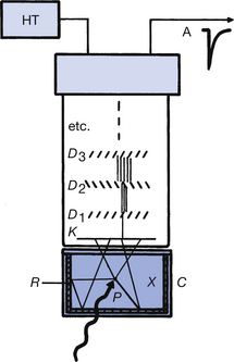
Figure 37.5 A scintillation detector using sodium iodide. D1, D2, etc., dynodes; C, crystal can; K, photocathode; R, powdered reflector; X, NaI(Tl) crystal.
If the photomultiplier tube contains n dynodes, each of which releases six electrons for one incident electron, then the electron gain in the photomultiplier tube is 6n. Thus, for a 10-dynode tube, the gain would be 610 which is just over 60 000 000 electrons and represents a charge at the anode of about 10 picocoulombs.
A spectrum of these pulses will not produce the discrete gamma energies emitted by the radioactive source because of the statistical nature of the light production in the crystal and the electron multiplication in the photomultiplier. This is shown in Figure 37.6 (see page 276), where the numbers of pulses of a given height are plotted. The true spectrum would be a line at the centre of the photopeak, as this corresponds to the energy of the gamma-rays absorbed by photoelectric absorption. In addition to the gamma-rays absorbed by photoelectric absorption, some of the gamma-rays undergo Compton scattering (see Sect. 23.6) within the crystal and then escape from the crystal with no further interactions. Such scattering interactions result in energy being deposited in the crystal which is less than the energy of the gamma-rays and so smaller pulses are produced in the photomultiplier. These pulses produce a ‘Compton peak’, as shown in Figure 37.6.
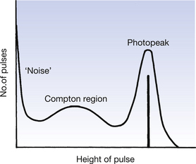
Some very-low-energy pulses are produced by the release of electrons from the photocathode by thermionic emission. There are also some positively charged ions produced at the dynodes which may strike the photocathode and cause it to release electrons. The electrons produced by both of the above mechanisms produce no useful signal and are referred to as ‘noise pulses’ (see Fig. 37.6).
37.5.2 The use of solid scintillation counters in medicine
It is usual practice to count only the pulses which occur in the photopeak of the spectrum, particularly when investigating the activity and distribution of a radionuclide within a patient’s body. This is achieved by the use of a pulse height analyser (PHA) which will only produce an electrical output signal if the input pulse lies within a certain range – this range is adjusted to cover the photopeak for the particular radionuclide. Pulses from the PHA are counted on a scalar for a time determined by the timer (see Fig. 37.7). The number of counts obtained is directly related to the activity being measured and may be compared to a normal range of values for that structure.
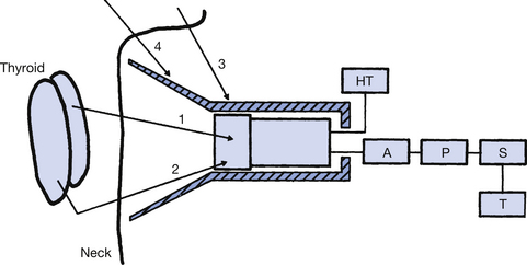
Figure 37.7 A scintillation detector used to measure activity within the thyroid gland. A, amplifier; P, pulse height analyser (PHA); S, scalar; T, timer.
An example of such a study will now be considered. The patient is given iodine-131 in the form of sodium iodide. The iodine component of this is taken up by the thyroid gland. The thyroid uptake may then be counted using equipment similar to that illustrated in Figure 37.7. The gamma-rays emitted from the thyroid are detected by the lead-shielded sodium iodide crystal and those which lie within the photopeak are counted as described above.
The possibility of gamma-rays emitted outside the thyroid (see rays 3 and 4) being counted is reduced by the lead collimator – this is the shaded area in Figure 37.7. The selection of a specific photopeak by the PHA allows the counter to reject radiations which impinge on the crystals as a result of Compton scattering of the gamma-rays (see ray 2). The uptake count is obtained by expressing the thyroid uptake as a percentage of the total radiation ingested by the patient. Typical figures for a ‘24-hour uptake’ lie between 10% and 25%. An overactive thyroid will give a higher figure and an underactive thyroid has a lower figure.
37.5.3 The gamma camera
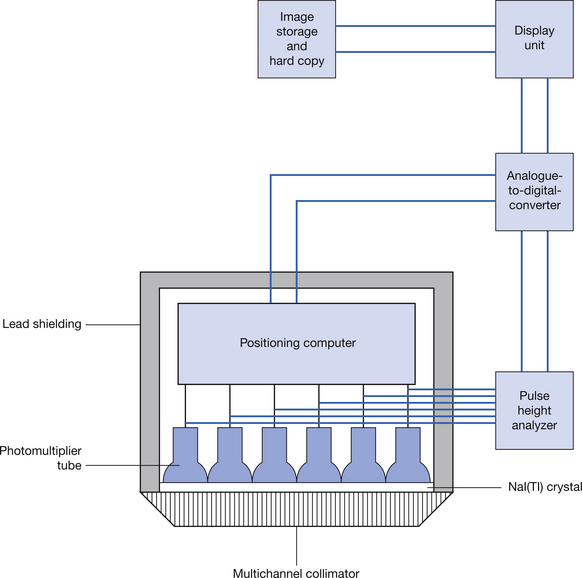
The gamma camera was first developed by HO Anger in 1958 and the camera and its associated technology have shown considerable progress since then. Many modern gamma cameras are dual headed so that scanning information in two plains can be collected simultaneously (see Fig. 37.8). The structure of the gamma camera and its associated circuitry is shown in Figure 37.9 (see page 278). The gamma camera is a specialized type of scintillation counter where the position as well as the count of the scintillations within a thin NaI(Tl) crystal (or multiple crystals) are obtained using a number of photomultipliers. A multichannel parallel collimator similar to that shown in Figure 37.7 ensures that only gamma-rays which are at right angles to the crystal face can enter the camera. A geometrical arrangement of photomultiplier tubes – of which there are typically around 120 – allows the position and the intensity of the scintillation produced in the crystal to be measured. This allows us to display a picture of certain physiological processes within the body. This ability to image a dynamic physiological process makes the gamma camera a very powerful tool in the detection of pathologies where the physiology of the structure is disrupted.
37.5.4 SPECT imaging
The acronym SPECT stands for single photon emission computed tomography and is now a useful tool in many nuclear medicine departments. Here a gamma camera is mounted on a suitable gantry so that it can either rotate round the patient or can move along the long axis of the patient. If the camera rotates around the patient, it produces a series of axial scans whereas the camera moving over the body produces a longitudinal scan (not unlike the scans produced by the old rectilinear scanners). If we consider the production of an axial scan, the camera is made to rotate around the patient as a series of stepped rotations. Each step is an equal arc e.g. 1° and information is collected at each step of the rotation. In the stepped rotation described, 360 different images would be collected in a complete rotation and these are then reconstructed to produce an axial image. The reconstruction techniques are similar to those used in CT scanning. This technique has a number of uses in nuclear medicine, mainly in cardiac profusion imaging and in oncology.
In this chapter, you should have learnt the following:
• The basic concept of radionuclide imaging (see Sect. 37.2).
• The production of artificially produced radionuclides (see Sect. 37.3).
• An overview of clinically useful radionuclides (see Sect. 37.4).
• The basis of radionuclide organ scanning (see Sect. 37.5).