Chapter 28 Rectification
Chapter contents
28.1 Aim
The aim of this chapter is to consider the various aspects of rectification as it applies to the X-ray generator. There is some initial discussion regarding the need for rectification and the ideal voltage waveform to apply to the X-ray tube, followed by a description of the rectification system in use today.
28.2 Introduction
In Chapters 10 and 14, it was seen that it is convenient to use an alternating current (AC) supply for diagnostic and therapeutic X-ray generators and linear accelerators because of the ease with which the potential can be stepped up or down. Both X-ray tubes and linear accelerators require a high potential difference across them in order to produce X-rays of the required energy. The voltage is stepped up using the high-tension transformer. However, the filament requires a potential of about 10 volts and a current of several amperes to heat it to a temperature sufficient for thermionic emission to occur, so the filament transformer (a step-down transformer) is used.
As shown in Chapters 21 and 30, the X-ray tube is designed to emit radiation when the cathode is negative and the anode is positive. The nearer the voltage across the tube is to a constant voltage, the more efficient the production of X-rays from the tube. This means that ideally we would like to change the alternating voltage supplied from the high-tension transformer to be turned into a constant unidirectional voltage. This process of converting an AC supply into a constant unidirectional supply, or a pulsating unidirectional supply, is called rectification. We will now consider different types of rectification in current use.
28.3 Four-diode full-wave rectification
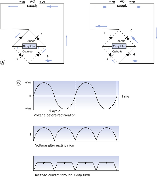
In order to utilize both halves of the AC cycle, full-wave rectification making use of four diodes arranged in a Gratz bridge circuit (Fig. 28.1) (see page 212) is used. Note that the diodes are arranged in two pairs and that the bar (or arrow) in the diode symbol always points away from the negative side of the output. D1 and D4 rectify one half cycle, while diodes D2 and D3 rectify the other half cycle. The arrows in Figure 28.1A show the direction of electron movement. It can be seen that electron movement across the X-ray tube is in the same direction in both half-cycles and that, although the potential varies, the anode never becomes negative. The circuit converts a 50-Hz AC supply into a pulsatile DC supply with 100 pulses per second.
28.4 Capacitor smoothing
Capacitor smoothing of a pulsating unidirectional voltage has already been discussed in Section 16.11.3. This is illustrated in Figure 28.2 (see page 213). The similarities between the resultant waveform and that in Figure 13.6 should be noted.
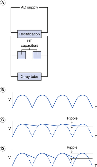
Figure 28.2 (A) Simplified diagram of a circuit with capacitor smoothing. (B) Effect of smoothing at different mA values. The shading indicates the effect of smoothing on the voltage ripple.
The capacitors charge up quickly when the exposure starts but discharge more slowly through the X-ray tube. This produces a reduction in the voltage ripple across the X-ray tube. Note that the amount of smoothing depends on the capacitance of the capacitor selected and the value of mA selected. A larger capacitor will store more charge (at a given voltage) than a smaller one. If the current through the X-ray tube is large, the capacitor will discharge more quickly and its potential will fall more rapidly. The high-tension cables used to connect the high-tension transformer to the X-ray tube also possess capacitance but it is quite small, so it only has a significant smoothing effect when the current is very small, e.g. during fluoroscopy. The result is that, although this voltage is smoother with less ripple, it is still not a constant potential. Note the amount of smoothing depends on the capacitance of the capacitor and the value of the mA selected.
Four-diode full-wave rectification (or the Gratz bridge circuit) was once the most commonly used rectification system. Today it is only used on its own in mobile X-ray units and dental and outpatient units. The Gratz bridge circuit is still found in modern generators where it forms an important part of the medium-frequency rectification system.
28.5 Medium-frequency generators
The improvement of semiconductor devices in solid-state rectification has led to the development of the medium-frequency generator (see Fig. 28.3). With the exception of intraoral dental units, which use solid-state single-phase full-wave rectification, this technology has superseded the older systems and is now found in almost all X-ray generators, including battery-powered mobile units.
At this point, it is useful to clarify the term ‘medium frequency’. Low-frequency systems operate at frequencies of up to 1000 Hz, medium-frequency systems operate in the range of 1000 Hz to 1 MHz while high-frequency systems operate at frequencies of 1 MHz and above.
The rectification system in these generators can be thought of as consisting of a number of subcircuits:
• The initial rectification and smoothing of incoming AC supply (if used).
• A frequency multiplication circuit.
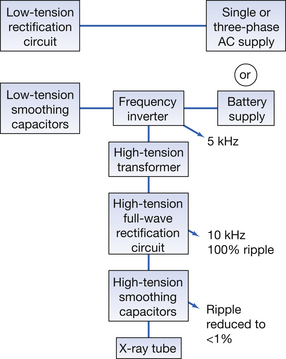
Note that the input supply may be from a battery, a single-phase AC or three-phase AC mains supply. If the input is from an AC supply, it is first rectified and smoothed by a large-capacitance low-tension smoothing circuit before passing to the inverter. A DC supply passes directly to the inverter.
The inverter has two functions:
1. It outputs the correct voltage to the fixed ratio high-tension transformer (HTT) to produce the required kVp.
2. It acts as a frequency multiplier, outputting a supply with a frequency of 5 KHz.
This is then rectified by a Gratz bridge rectification circuit producing a supply with a frequency of 10 KHz. This then passes through a capacitor smoothing circuit, which uses high-tension smoothing capacitors, and then passes to the X-ray tube. Because the frequency is so high, the interval while the voltage is dropping and the capacitor is discharging is very short and the ripple present after smoothing is less than 1%. The result can be regarded as an (almost) constant potential output.
These systems have additional advantages. The increased frequency results in improved transformer efficiency. This means that the high-tension transformer can be made less bulky, leading to improvements in the overall design of the unit and the possibility of using a single-tank X-ray tube.
In this chapter, you should have learnt the following:
• The reasons an AC supply is required for an X-ray generator and why this needs to be rectified before it is applied to the X-ray tube (see Sect. 28.2).
• The rectification used in a single-phase full-wave unit and the voltage waveform produced (see Sect. 28.3).
• How capacitors may be used to smooth a full-wave rectified waveform (see Sect. 28.4).
• How rectification is attained in modern generators using a medium-frequency rectification system (see Sect. 28.5).
Further reading
Ball J.L., Moore A.D., Turner S. Ball and Moore’s Essential Physics for Radiographers, fourth ed. London: Blackwell Scientific, 2008. (Chapter 13)
Curry T.S.III, Dowdey J.E., Murry R.C.Jr. Christensen’s Physics of Diagnostic Radiography, fourth ed. London: Lee & Febiger, 1990. (Chapter 3)
Dowsett D.J., Kenny P.A., Johnston R.E. The Physics of Diagnostic Imaging. London: Chapman & Hall Medical, 1998. (Chapter 4)
Thompson M.A., Hattaway R.T., Hall J.D., Dowd S.B. Principles of Imaging Science and Protection. London: W B Saunders, 1994. (Chapter 7)