chapter 6 Image Receptors
Afterglow: The tendency of a luminescent compound to continue to give off light after x-radiation has stopped.
Base: A transparent flexible polyester support layer of radiographic film.
Cassette: A lightproof encasement designed to hold x-ray film and intensifying screens in close contact.
Emulsion: A layer of radiographic film made of gelatin containing suspended silver halide crystals.
Film latitude: The exposure range of a film that will produce acceptable densities.
Fluoroscopy: A special radiographic diagnostic method by which a “live view” of the internal anatomy is possible.
Intensifying screens: Sheets of luminescent phosphor crystals bound together and mounted on a cardboard or plastic base.
Latent image: An invisible image on the x-ray film after it is exposed to ionizing radiation or light before processing.
Nonscreen film: Film that is more sensitive to ionizing radiation than to fluorescent light.
Quantum mottle: An artifact of faster screens that results in density variation due to random spatial distribution of the phosphor crystals within the screen.
Reflective layer: A layer of an intensifying screen that reflects the light from the phosphor layer toward the film.
Screen film: Film with silver crystals that is more sensitive to fluorescent light emitted from intensifying screens than to ionizing radiation.
Silver halide: A compound of silver and bromine, chlorine, or iodine, all of which are in the halogen group of elements.
INTRODUCTION
In previous chapters, discussions were limited to the production and action of x-rays. To further understand radiography, we need to discuss how a permanent record is produced using x-rays.
Essentially, a radiograph is formed with light-sensitive film contained in a lightproof encasement. In radiography, the lightproof encasement used most often is called a cassette (Fig. 6-1). The general-use cassette is designed to hold a piece of double-emulsion x-ray film sandwiched between two fluorescent sheets of plastic called intensifying screens. The intensifying screens are responsible for converting the x-ray radiation into visible light, which creates a latent image on the x-ray film. The film is then processed to convert the latent image into a visible image. Remarkably, more than 95% of the exposure recorded on the film is due to the light emitted from the intensifying screens. Only 5% of the exposure of the film results from the ionization of x-rays.
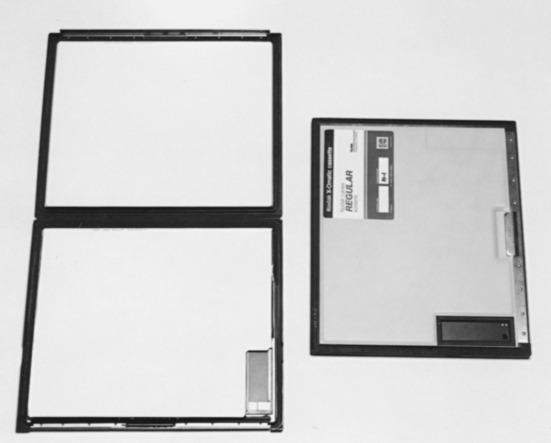
Figure 6-1 Two cassettes, one open and one closed. Inside the cassette are two fluorescent screens that sandwich the radiographic film. When closed, the cassette provides a lightproof environment for the film.
Many different types of image receptors and detectors convert invisible ionizing radiation into a visible image. These detectors and receptors can take many forms and, in turn, assist a number of diagnostic procedures that use radiant energy including the following:
This list is only a sample of the imaging techniques that use radiant energy. We will redirect our attention to fluorescent intensifying screens and silver halide films as image receptors.
THE CASSETTE
In radiography, the cassette is a rigid film holder designed to hold the x-ray film and intensifying screens in close contact. The cassette must be constructed with materials that are light-tight to prevent any unwanted exposure to the film yet that allow penetration of the x-rays.
The first cassettes were constructed with cardboard. This material could not be reused and thus did not pass the test of time. Over the years, cassettes made of aluminum became standard. Aluminum cassettes are still common today; however, improvements have been made to cassette fronts. As mentioned, the front of the cassette must be strong and opaque to light yet radiolucent to x-rays. Examples of available cassette fronts are those made of (1) polycarbonate (Bakelite), (2) aluminum, (3) magnesium, and (4) carbon fiber.
Some cassette fronts are color coded or have a colored dot on the edge to indicate the screen type inside. Color coding allows easy identification when choosing a cassette for each clinical situation. The front may also be marked into four quadrants to assist more than one exposure per film. Taking a number of exposures on one film is accomplished by exposing one quadrant while shielding the others with lead rubber strips (Fig. 6-2). An area approximately 3 × 7 cm may also be marked in the corner of the cassette front to indicate the presence of a lead blocker (Fig. 6-3). This lead blocker is present to prevent irradiation of the part of the film necessary for identification. (Film identification is discussed in Chapter 7.) Care must be taken not to superimpose any vital areas of the patient over this blocker.
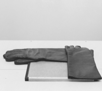
Figure 6-2 The cassette has been divided into four quadrants so that a number of views can be exposed. Three of the sections are being shielded with lead to prevent exposure until desired. In this case the quadrants are being shielded with lead gloves. Commercially available lead sheets can be purchased for this purpose as well.
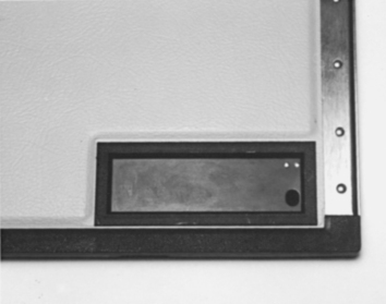
Figure 6-3 A 3 × 7 cm lead blocker for photographic identification. The blocker prevents exposure to x-rays to this area so that information can be exposed on the film in the darkroom with the use of a photoimprinter.
The cassette front is attached to the back with hinges and catches. Several types of hinges and catches that provide a tight seal between the front and the back of the cassette are available. The closure styles range from hinges with slide catches to crossbars that pivot on a shoulder rivet in the middle of the back of the cassette. The back of the cassette is constructed with heavier material than that for the front and is normally lined with lead to absorb backscatter radiation that would cause fogging of the film.
Inside the cassette, both sides are lined with felt or foam pressure pads that ensure close contact of the film and screens. The choice of felt versus foam pads varies with each cassette manufacturer.
Cassette sizes also vary and correspond to screen and film sizes (in both metric and English). Their cost varies according to size and quality. (Note: The price quotes in most catalogs are for the cassettes only and do not include the screens.)
Cassette choice is an important aspect of veterinary radiography. The purchase of a certain cassette may help or hinder the production of quality radiographs. A cassette should have sturdy construction, maintain screen-film contact, and be user friendly in the darkroom.
Cassette Care
As with any expensive piece of equipment, the cassette should be handled with care. In veterinary medicine, cassettes tend to be exposed to some physical abuse. This is especially true in a large-animal practice. The most common causes of physical damage are (1) dropping the cassette on a hard surface and (2) leakage of fluid such as blood or urine into the cassette.
Dropping a cassette on a hard surface can result in a loss of contact between the screens and film, which results in a blurred radiographic image. (See Chapter 10 for the test procedure for screen-film contact.)
Keeping a cassette clean when working with animals is always a challenge. Precautions such as placing the cassette in a plastic bag when a “messy” situation is expected will prevent damage to the cassette’s exterior and interior. A cassette should be cleaned on a regular basis with mild soap and water. Cleaning the exterior of the cassette when the screens are cleaned (monthly) is usually adequate unless circumstances necessitate a more frequent schedule.
All cassettes should be numbered. This way, any noticeable defects on a radiograph can be traced to the “problem” cassette. Most intensifying screens within the cassette have a serial number imprinted on the screen edge. These numbers are small, however, and difficult to read. The best method of cassette identification is to number each intensifying screen near the edge or corner with a black felt-tip marker. This number will appear on each radiograph taken with that cassette. The exterior (back of the cassette) should be marked with the same number.
INTENSIFYING SCREENS
Intensifying screens are sheets of luminescent phosphor crystals bound together and mounted on a cardboard or plastic base. Two screens are normally inside the cassette to sandwich the x-ray film, which has a coating of light-sensitive emulsion on both sides (double emulsion). When the phosphor crystals in the screen are struck by x-radiation, the crystals fluoresce, and x-rays are converted into visible light (Fig. 6-4). This visible light exposes the x-ray film. As stated earlier, more than 95% of the exposure to the film is due to light emitted from the intensifying screens.
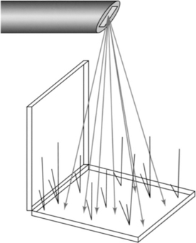
Figure 6-4 Fluorescent screens emit light when x-rays strike them. This drawing illustrates how the screens “glow” during exposure.
The primary purpose of the intensifying screen is to reduce the amount of radiation exposure required to produce a diagnostic radiograph. The use of screens results in lower milliamperage-seconds (mAs), thus decreasing the dose of radiation to the patient and the chance of motion on the radiograph.
Three properties determine the efficiency of the screen materials:
Screen Construction
An intensifying screen has four integral layers: (1) a base or support, (2) a reflective layer, (3) a phosphor crystal layer, and (4) a protective coat (Fig. 6-5).
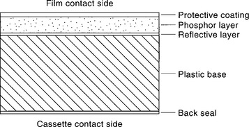
The base serves as a flexible support to attach the phosphor layer to the cassette. The base must have a tough, moisture-resistant surface and not become brittle with extended use.
The reflective layer, which is attached to the base, is made of a white substance such as titanium dioxide. The purpose of the reflective layer is to reflect the light emitted by the phosphor layer back toward the x-ray film. The reflective layer increases the efficiency of the screen so that none of the light photons are lost through the base layer.
The phosphor crystal layer consists of uniformly distributed phosphor crystals held in place with a binder material. It is extremely important that this layer not change in thickness, crack, or discolor with age. Any variance in screen uniformity would alter the amount of light produced when irradiated and would alter the uniform exposure of the film (Fig. 6-6).
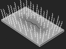
Figure 6-6 A crack in an intensifying screen. During exposure to x-rays, an irregular light emission results where the screen is damaged.
The protective coat is a clear coating placed on the outer surface of the screen; it provides the necessary protection to the phosphor layer. This layer must be strong enough to resist marks and abrasions and easy to clean. Veterinary radiography has many pitfalls, one of which is animal hair. Any foreign material caught in the cassette between the intensifying screen and the film will alter the exposure to the film. The debris on the screen will result in radiographic artifacts (Fig. 6-7). Because of the likelihood of artifacts and the need for subsequent screen cleaning, the protective surface must be durable and resistant to deterioration.
Phosphor types.
As discussed previously, x-rays can cause phosphors to emit light. The phosphor chosen for an intensifying screen must absorb x-rays efficiently, have a minimum afterglow, and emit sufficient light of the desired color.
Afterglow is the tendency of a phosphor to still give off light after the x-radiation has stopped. This continued phosphorescence can interfere with rapid-succession serial film changers. A serial film changer is used when a number of films are necessary per second. For example, a rapid serial film changer is necessary for angiography to view the action of the heart. With a radiopaque liquid contrast medium injected intravenously, the movement of the fluid through the chambers of the heart can be recorded. A serial film changer can expose many films per second. If any afterglow from the intensifying screen were present, it would interfere with the exposure of each successive film.
The absorption rate of the phosphor refers to the extraction of x-ray photons from the beam. The absorption of one x-ray quantum (unit of radiant energy) results in the emission of hundreds of light quanta from the screen. These light photons are more readily absorbed by the x-ray film than are x-ray photons. The more x-ray quanta absorbed, the greater the amount of light produced.
The first phosphor intensifying screen, introduced in 1896 by Thomas Edison, was made of calcium tungstate, which was chosen because its emission of light is in the blue regions of the ultraviolet spectrum. This was important because of the high sensitivity of silver halide to this spectrum of light. Calcium tungstate has a relatively high x-ray absorption ability and is physically strong, but it is lacking in light conversion efficiency. Despite this weakness, calcium tungstate screens are still widely used today.
GENERAL RULES
New phosphor technology has led to the introduction of phosphors with greater speed. In 1972 a class of phosphors known as the rare-earth elements was developed. The term rare earth is used because these elements are difficult and expensive to separate from the earth and from each other, not because they are scarce. The rare-earth group is also known as the lanthanide series because it consists of elements with atomic numbers 57 (lanthanum) through 71 (lutetium).
The x-ray–to-light conversion efficiency of rare-earth phosphors is significantly greater than that of calcium tungstate. The light conversion of a rare-earth screen is four times as great as that of a calcium tungstate screen. The spectral emission of rare-earth phosphors is in the green light part of the spectrum. Because standard x-ray silver halide film will not absorb (i.e., is not sensitive to) light in the green area, a special film that is sensitive to the green spectrum of light must be employed with this type of screen.
Screen Speed
Factors other than phosphor type affect the speed and efficiency of a screen. Many types of screens are available today, all of which are graded by their speed and efficiency. Screen speed is governed by crystal size, phosphor layer thickness, reflective layer efficiency, and dyes in the phosphor layer.
Crystal size.
Within certain limits, the larger the crystal, the greater its light emission. An x-ray striking any part of a phosphor crystal causes the entire crystal to fluoresce. Because of the larger flashes of light with larger crystals, less x-radiation is necessary to expose the x-ray film (Fig. 6-8). Another way to consider this concept is illustrated in the following scenario.
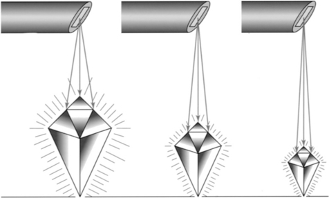
Figure 6-8 One factor that influences the speed of screens is the size of the phosphor crystals. A large crystal emits a larger amount of light than a smaller crystal.
Imagine that you are standing 10 feet away from a wall that has two mirrors hanging on it. One mirror is 2 inches in diameter, and the other is much larger with a 10-inch diameter. Facing the wall, you shine a flashlight beam at the mirrors. As you examine the light being reflected, you notice that the amount of light from each mirror is not equal. What is reflected from the smaller mirror is significantly less than that from the larger mirror.
The same principle applies to phosphor crystal size. Unfortunately, as the crystal size increases, the detail of the image decreases. The result of increasing the speed of the screen by increasing the crystal size is a grainy image. Within certain limits, an increase in crystal size is acceptable and will not compromise radiographic detail excessively. In comparison, smaller crystals produce a film with increased detail but larger amounts of radiation are required.
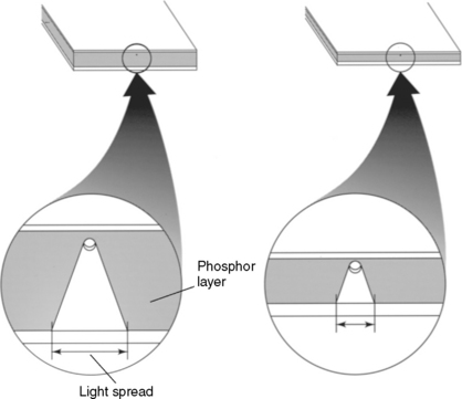
Phosphor layer thickness.
The thickness of the phosphor layer is another factor that influences both screen speed and image detail. When the thickness is increased, the x-ray absorption and light emission are increased. Screen thickness has limits, however. An increase in the thickness of the phosphor layer results in a decrease in image detail. The image is blurred as a result of the diffusion, or “spreading out,” of the light as it travels through the screen from the phosphor crystal, where the light originated. Recall that light leaves a central point and diverges outward. Lateral spreading of light is a result of this light divergence (Fig. 6-9).
Reflective layer efficiency.
As mentioned earlier, the reflective layer is positioned between the base and the phosphor layer. The purpose of the reflective layer is to reflect all light emission from the phosphor layer toward the x-ray film. If the reflective layer contains a light-absorbing material, however, a portion of the light produced by the phosphors will be lost. More x-radiation is necessary to produce an adequate exposure on the x-ray film. Therefore it is important that the reflective layer material has a high reflective capability and a low absorption capacity.
Dyes in the phosphor layer.
A light-absorbing dye (pigment) may be incorporated into the binder material of the phosphor layer of some screens. The primary purpose of the dye is to decrease lateral spreading of the light emitted from the phosphor crystals. When the lateral spread is reduced, blurring of the radiographic image is decreased. Unfortunately, the light intensity emitted by the screen is also reduced and the speed of the screen is decreased. Common pigments used are yellow, gray, and pink.
Screen Speed Ratings
Because many factors affect screen speed, it is natural to assume that there are many screens from which to choose. It might also be assumed that screen speeds can be accurately measured and that screen speed categories are clearly defined. Unfortunately, this is not the case; screen speed categories are broad and general. Most manufacturers divide screen speeds into three basic categories relative to the screen’s light output:
One manufacturer’s screen speed categories may not correlate precisely with another’s. For example, manufacturer A may produce a par speed screen that is 10% faster than the par speed screen produced by manufacturer B.
Increased screen speed has led to a radiographic artifact known as quantum mottle. This artifact gives a radiograph a spotty or mottled appearance. Quantum mottle occurs because the new, faster screens are so sensitive that only a few x-ray quanta are necessary to produce the desired density on the x-ray film. As the small number of quanta strike the intensifying screen, not all of the phosphor crystals are struck and therefore not all of them fluoresce. Inconsistent fluorescence from the phosphors results in a density variation (mottling) on a uniformly exposed radiograph. Quantum mottle is a disadvantage of rare-earth screens for brief exposures, but its effects are greatly reduced with correct film-screen combinations.
Screen Speed Summary
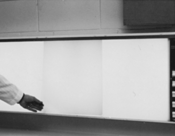
In radiography, screen speed is inversely proportional to the exposure required to produce a given effect. That is, a fast screen requires a small exposure, and a slow screen requires a larger exposure. A fast screen has the physical capability to emit more light when struck by x-radiation than does a slow screen, given the same exposure (Fig. 6-10).
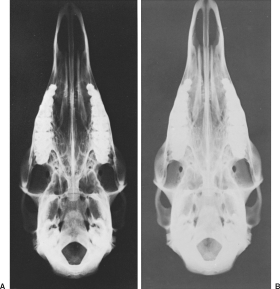
Figure 6-10 These two radiographs were exposed with identical exposure factors with the use of two different screen types. A was exposed with fast screens, and B was exposed with slow screens. Note that A is properly exposed, whereas B is too light. Slow screens need a greater amount of exposure compared with fast screens.
In the same respect, radiographic detail is inversely proportional to the speed of the screen. A screen that is manufactured to be fast will inherently produce a radiograph with less detail. The disadvantage of fast screens is increased graininess. Although slow screens require more x-radiation, the detail is greatly increased.
Mounting Screens in the Cassette
Intensifying screens are usually mounted in pairs in the cassette. Most screens are labeled FRONT and BACK and should be placed in the cassette appropriately. The screen on the front side is slightly thinner than that on the back so that the front does not absorb an excessive amount of the x-ray beam and the exposure of light to both sides of the film is even.
Securing the screens in the cassette is vital. Screens should never be loose inside the cassette. Double-sided tape, provided by the manufacturer, should be applied to secure the screens. Commercial liquid adhesives should be avoided because certain chemicals can interact with the screens.
Some screens are used singly in a cassette. The use of only one screen increases the image resolution but tends to be slower and to need more exposure to achieve a desired product. Single-screen cassettes are used primarily for extremity radiography, in which image detail is critical, and must be paired with single-emulsion film.
Specialized Screens: Fluoroscopy
Fluoroscopy is essentially the visualization of a “live” or “real-time” radiographic image. Fluoroscopy is used for a number of purposes including the following:
The main feature of a fluoroscopy unit is its screen. Special crystals such as cadmium sulfide or caesium iodide are in the screen because they emit green light, to which the human eye is most sensitive. The screen is substituted for conventional x-ray film and is placed in the path of the x-ray beam after it has passed through the patient. The fluoroscopic screen enables the radiographer to visualize the fluorescent image created by the interaction of x-rays and phosphor crystals as it occurs.
The image viewed is the opposite of an x-ray seen on a view box, or a “positive” image. The black-and-white areas on the screen are reversed compared with a normal radiograph. The intensity of the light emitted by each part of the screen is proportional to the intensity of the x-rays striking that part of the screen. The visible light pattern corresponds precisely with the x-ray pattern.
Fluoroscopy equipment is installed opposite to conventional x-ray equipment. The fluoroscopic screen is suspended above the x-ray table, and the x-ray tube, coupled to the screen, is under the table directed toward the screen (Fig. 6-11). Leaded glass is positioned over the screen so that the image can be viewed without exposing the operator’s eyes to radiation.
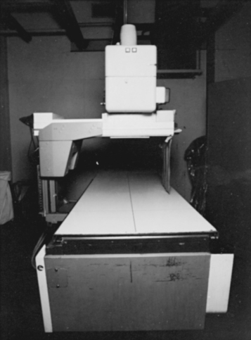
Figure 6-11 Fluoroscopy unit. The x-rays are emitted from under the table and projected on a fluorescent screen above the table. The image is then transferred to a television monitor.
Today, technology has replaced this type of fluoroscopy unit with an image-intensifying unit. An image intensifier essentially converts and transfers the image on the intensifying screen to a photoelectric surface. Image-intensified fluoroscopy can be observed through an optical lens and mirrors (mirror optics system) or on a television monitor.
At no time should fluoroscopy replace radiography. Not only is there more risk of radiation exposure, but the image created by the fluoroscope has far less resolution. In the past, some veterinary practices used handheld fluoroscopy units exclusively to save the time and expense of exposing and developing x-ray film. This practice is deemed illegal in most states in the United States.
Screen Care
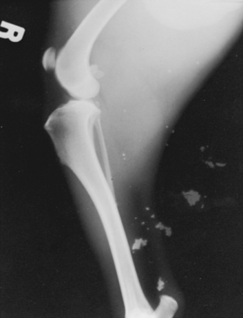
Because of the cost of screens and their sensitivity to damage, the importance of screen care cannot be minimized. Screens should be inspected and cleaned on a regular basis to keep them free of dirt and foreign material. Dust and animal hair are common artifacts in veterinary radiography (Fig. 6-12). Any abrasion, chemical spill, or artifact will be noticeable on all films taken in conjunction with that screen. Incorrect diagnoses have occurred as a result of unsuspected screen artifacts.
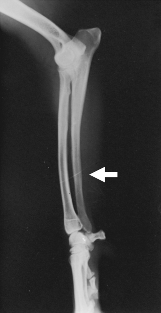
Figure 6-12 Radiograph showing a hair artifact. The hair was trapped inside the cassette during exposure.
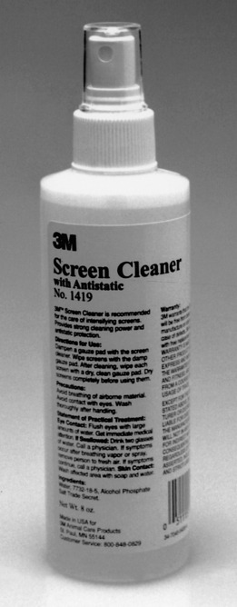
Screens should be cleaned according to the manufacturer’s instructions to avoid damage to the screen surfaces. For example, a soft brush or pressurized air can remove loose foreign material. The surface protective coat can be cleaned by careful swabbing with dampened gauze pads and cleaning solution. Commercial screen cleaning solutions (Fig. 6-13), mild soap and water, or dilute ethyl alcohol are recommended. Commercial solutions have the advantage of possessing antistatic properties.
After cleaning, the cassette should be left open and propped in a vertical position to dry completely before reloading. The vertical position prevents any dust or foreign material from settling inside the cassette. At all other times, the cassette should be kept closed to prevent accidental damage and artifacts. Take care when loading and unloading film from the cassette to avoid “digs” and scratches on the screen surface. Touching the screens and writing on film that is still in the cassette should also be avoided. Damage to the screen surface is permanent and cannot be repaired.
X-RAY FILM
The purpose of x-ray film is to provide a permanent record containing essential diagnostic information. X-ray film provides information not only for present use but for later evaluation as well.
X-ray film consists of a polyester base coated on both sides with a light-sensitive emulsion containing silver halide crystals. When visible light or ionizing radiation (x-rays) interacts with the silver halide crystals, an invisible (latent) image is formed. Through processing, this invisible image is converted into a visible image. The final product is a radiograph.
Film Composition
X-ray film has a number of layers, each with individual characteristics and purposes (Fig. 6-14). The transparent polyester base provides a flexible support with a thin adhesive subcoating on each side. The adhesive serves to bind the next layer, the emulsion, to the base. Emulsion consists of gelatin that contains silver halide microcrystals suspended and dispersed evenly throughout the layer. Gelatin provides reasonable permanence and allows rapid processing because it is easily penetrated by developing solutions.
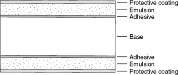
Silver halide is a compound of silver and bromine, chlorine, or iodine, which are members of the halogen family. (Silver bromide crystals are common in diagnostic x-ray film.) Viewed through a microscope, the emulsion appears to be filled with tiny grains of sand. These tiny grains are the silver microcrystals suspended in the gelatin—there are billions of crystals per cubic centimeter of emulsion. Over the emulsion is a clear supercoat of protective material to decrease the possibility of damage to the fragile emulsion.
Latent Image
As the silver halide crystals absorb energy from visible light or x-rays, a physical change occurs and a latent image is formed. By definition, a latent image is an invisible image on the x-ray film after it is exposed to ionizing radiation or visible light before processing. After processing with a special chemical developer solution, the latent image is converted into a visible image.
The latent image is formed on a screen-type film by the absorption of a light photon by a grain of silver halide. When exposed, the silver halide is converted to metallic silver. The greater the number of silver halide crystals that are converted to metallic silver, the blacker the film will be once developed. The unexposed silver halide crystals are cleared off the film during the fixing portion of the processing procedure. A film that has not been exposed to any ionizing radiation or visible light will be clear after processing because none of the silver halide crystals were converted to metallic silver (Fig. 6-15).
Film Types
The two general categories of film used in diagnostic radiography are screen and nonscreen.
Screen film.
Screen film is manufactured with silver crystals that are sensitive to fluorescent light emitted from intensifying screens and less sensitive to ionizing radiation. This type of film requires less exposure of x-rays to produce a quality image because of its high sensitivity to fluorescent light.
For many years, screen film has primarily been “blue-sensitive,” that is, highly responsive to the ultraviolet, violet, and blue spectrum of light. Today, newer films have been developed that are sensitive to green light as well. The importance of this is linked to the new generation of intensifying screens known as rare-earth screens. Some rare-earth screens emit primarily a green spectrum of light, whereas calcium tungstate uses phosphors that convert the energy of x-rays into blue light. Because of this variation, it is important to match a suitable film to an appropriate screen.
Nonscreen film.
Nonscreen film is exposed by the direct action of x-radiation. This type of film is manufactured to be more sensitive to ionizing radiation. Because there is no intensification of the x-ray beam, greater exposures are required. However, because intensifying screens are not used, there is no loss of detail due to the screens. The resulting radiographs have greater detail. This film is of particular value in bone or dental radiography, but because of the necessity for greater exposure, nonscreen film should be used only for areas where tissue thickness is minimal.
One problem with nonscreen film is the absence of a strong protective cover. The film is normally packaged in a light-tight envelope made of heavy paper. Because this paper offers little protection, the film is highly sensitive to pressure (e.g., from a dog’s nails when extremities are being radiographed).
Film Speed
Film is manufactured with various speeds through the use of different-sized silver halide crystals. Speeds of radiographic films are determined from the exposures required to produce an image with adequate density. The exposure range over which acceptable densities are produced is known as film latitude. Film that has “wide” latitude will accept a significant variation in exposure factors or processing without exhibiting a great change in density. On the one hand, wide-latitude film is considered a “forgiving” film. Narrow-latitude or high-contrast film, on the other hand, requires considerably less change in exposure factors or processing to alter the radiographic density.
To maintain simplicity, we will examine film speed in three basic groups:
In veterinary radiography, the most common film is medium speed, also known as standard or par speed. This category is a compromise between fine detail and speed. Medium-speed film is suitable for a wide range of examinations and acts as a standard by which manufacturers rate other films. Medium-speed film is often the only type of film stocked in a veterinary practice.
Film Care
Because of the delicate nature of x-ray film, specifically in terms of the emulsion layer, film handling and storage are of great importance.
Film boxes should be stored on end so that the film is vertical. If the film is stored horizontally for an extended period or if any pressure is placed on the film, the emulsion on each sheet may blend together. The result may be a “block” of x-ray film that is useless. The temperature of storage is also important. The storage area should be cool (10° to 15°C) and have a low relative humidity (40% to 60%). Excessive heat and humidity can result in softening of the film emulsion, causing the film to stick together and, in effect, decrease its shelf life.
Film should not be stored near any source of ionizing radiation or where vapors from formalin, hydrogen peroxide, or ammonia can reach it. These substances can cause fogging.
Close observation of the film expiration date, marked on the end of each box, is also important. If a number of boxes are stored, the film should be used in sequence to avoid expired film.
FILM-SCREEN SYSTEMS
For the technologist to know the speed of the film and screen alone is not enough. Knowledge of the film-screen “combination” is vital. The combined speed or “system speed” is what determines the exposure requirements for any given clinical situation. A wide assortment of film-screen combinations is available. The choice of a system depends on the desired image detail and necessary speed requirements. In some instances the fastest system possible must be used because of the anticipated studies or because of the relatively low-powered equipment.
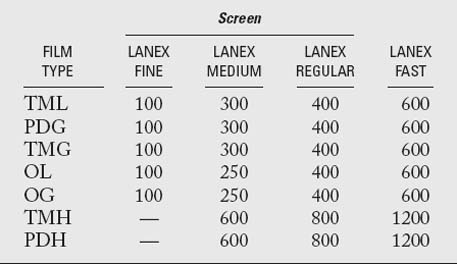
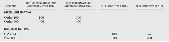
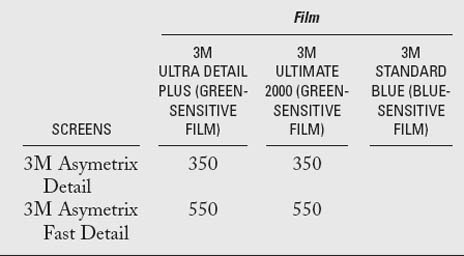
A numeric value is assigned to each film and screen type. Unfortunately, each film manufacturer has its own manner of speed evaluation, and these may not correlate. In veterinary practice, a medium-speed system (300 to 400) is the most common because of its versatility. See Tables 6-1 through 6-3 for lists of common film-screen system speeds. To acquire specific information concerning the system speed in a given practice, the film manufacturer should be consulted. In general the numeric value for film-screen combination ranges from about 25 to 1200. Although these numbers resemble those of the ASA (ISO) system for photographic film, the standards are not as rigid.
Bushong SC. Radiologic science for technologists, ed 7. St Louis: Mosby, 2001.
Eastman Kodak Company. Kodak: the fundamentals of radiography, ed 12. Rochester, NY: Kodak, 1980.
Koblik P, Hornof JW, O’Brien TR. Rare-earth intensification screen for veterinary radiography: an evaluation of two systems. Vet Radiol. 1980;21:224-232.
Morgan JP, Silverman S. Techniques in veterinary radiography, ed 4. Ames, IA: Iowa State University Press, 1987.
Schmidt RA, et al. Evaluation of cassette performance: physical factors affecting patient exposure and contrast. Radiology. 1983;146:801-806.