Instrumentation for Basic Oral Surgery
The purpose of this chapter is to introduce the instrumentation commonly required to perform routine dental extraction and other basic oral surgical operations. These instruments are used for a wide variety of purposes, including soft and hard tissue procedures. This chapter primarily deals with a description of the instruments.
INCISING TISSUE
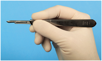
Many surgical procedures begin with an incision. The primary instrument for making incisions is the scalpel, which is composed of a reusable handle and a disposable, sterile sharp blade. Scalpels are also available as a single-use scalpel with a plastic handle and fixed blade. The most commonly used handle for oral surgery is the No. 3 handle (Fig. 6-1). The tip of a scalpel handle is prepared to receive a variety of differently shaped scalpel blades to be inserted onto the slotted portion of the handle.
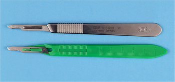
FIGURE 6-1 Scalpels are composed of handle and sharp, disposable blade. Scalpel No. 3 handle with No. 15 blade is most commonly used.
The most commonly used scalpel blade for intraoral surgery is the No. 15 blade (Fig. 6-2). The blade is small and is used to make incisions around teeth and through soft tissue. The blade is similar in shape to the larger No. 10 blade used for large skin incisions in other parts of the body. Other commonly used blades for intraoral surgery include the No. 11 and No. 12 blades. The No. 11 blade is a sharp-pointed blade that is used primarily for making small stab incisions, such as for incising into an abscess. The hooked No. 12 blade is useful for mucogingival procedures in which incisions are made on the posterior aspect of teeth or in the maxillary tuberosity area.
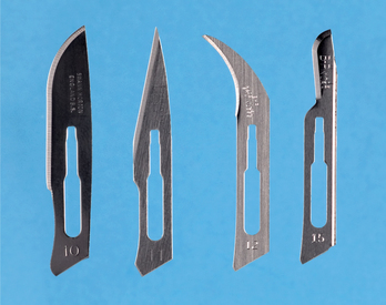
FIGURE 6-2 Scalpel blades used in oral surgery include No. 10, No. 11, No. 12, and No. 15, going from left to right.
The scalpel blade is carefully loaded onto the handle holding the blade with a needle holder. This lessens the chance of injuring the fingers. The blade is held on the unsharpened edge, where it is reinforced with a small rib, and the handle is held so that the male portion of the fitting is pointing upward (Fig. 6-3 A). The scalpel blade is then slowly slid onto the handle along the grooves in the male portion until it clicks into position (Fig. 6-3, B). The scalpel is unloaded similarly. The needle holder grasps the end away from the blade (Fig. 6-3, C) and lifts it to disengage it from the male fitting. The scalpel is then slid off the handle (Fig. 6-3, D). The used blade is immediately discarded into a specifically designed, rigid-sided sharps container. These are usually red (see Fig. 6-6).
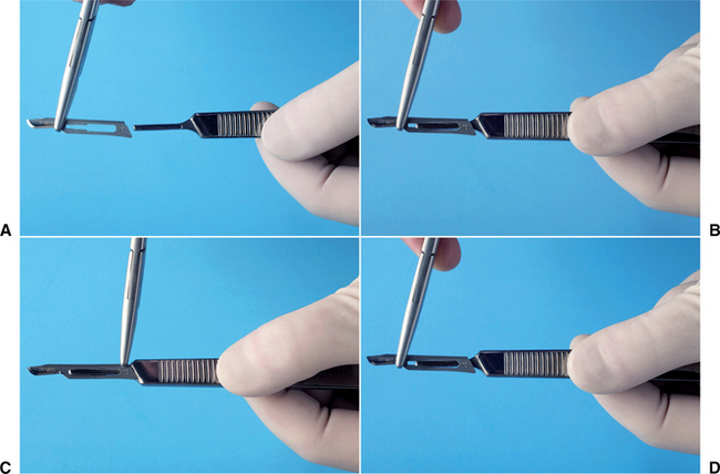
FIGURE 6-3 A, When loading scalpel blade, surgeon holds blade in needle holder and handle, with male portion of fitting pointing upward. B, Surgeon then slides blade into handle until it clicks into place. C, To remove blade, the surgeon uses needle holder to grasp end of blade next to the handle and lifts it to disengage it from the fitting. D, Surgeon then gently slides blade off the handle.
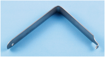
FIGURE 6-6 Austin retractor is a right-angle retractor that can be used to retract cheek, tongue, or flaps.
When using the scalpel to make an incision, the surgeon typically holds it in the pen grasp (Fig. 6-4) to allow maximal control of the blade as the incision is made. Mobile tissue should be held firmly in place under some tension so that as the incision is made, the blade will incise and not just push away the mucosa. When incising depressible soft tissue, an instrument such as a retractor should be used to hold the tissue taut during incision. When a mucoperiosteal incision is made, the blade should be pressed down firmly so that the incision penetrates the mucosa and periosteum with the same stroke.
Scalpel blades and blade-handle sets are designed for single-patient use. They are dulled easily when they come into contact with hard tissue such as bone or teeth, and even after repeated strokes through keratinized tissue. If several incisions through mucoperiosteum to bone are required, it may be necessary to use a second blade during a single operation. Dull blades do not make clean, sharp incisions in soft tissue and therefore should be replaced before they become overly dull.
ELEVATING MUCOPERIOSTEUM
When an incision through periosteum is made, ideally the periosteum should be reflected from the underlying cortical bone in a single layer with a periosteal elevator. The instrument that is most commonly used in oral surgery is the No. 9 Molt periosteal elevator (Fig. 6-5). This instrument has a sharp, pointed end and a broader, rounded end. The pointed end is used to begin periosteal reflection and to reflect dental papillae from between teeth, and the broad, rounded end is used to continue the elevation of periosteum from the bone.
Other types of periosteal elevators exist for use by periodontists, orthopedic surgeons, and other surgeons involved in work on bones.
The No. 9 Molt periosteal elevator can be used to reflect tissue by three methods: First, the pointed end can be used in a twisting, prying motion to elevate soft tissue. This is most commonly used when elevating a dental papilla from between teeth or the attached gingiva around a tooth to be extracted. The second method is the push stroke, in which the pointed or the broad end of the instrument is slid underneath the periosteum, separating it from the underlying bone. This is the most efficient stroke and results in the cleanest reflection of periosteum. The third method is a pull stroke. This method is occasionally useful but tends to shred or tear the periosteum unless it is done carefully.
RETRACTING SOFT TISSUE
Good access and vision are essential to performing excellent surgery. A variety of retractors have been designed to retract the cheeks, tongue, and mucoperiosteal flaps to provide access to visibility during surgery. Retractors also can help protect soft tissue from sharp cutting instruments.
The two most popular cheek retractors are (1) the right-angle Austin retractor (Fig. 6-6) and (2) the broad offset Minnesota retractor (Fig. 6-7). These retractors can also be used to retract the cheek and a mucoperiosteal flap simultaneously. Before the flap is created, the retractor is held loosely in the cheek, and once the flap is reflected, the retractor edge is placed on the bone and is then used to retract the flap.
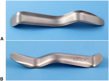
FIGURE 6-7 Minnesota retractor is an offset retractor used for retraction of cheeks and flaps. A, Front. B, Back.
The Seldin retractor is another type of instrument (Fig. 6-8) used to retract oral soft tissues. Although this retractor may look similar to a periosteal elevator, the leading edge is not sharp but instead is smooth; it should not be used to elevate mucoperiosteum. The No. 9 Molt periosteal elevator can also be used as a retractor. Once the periosteum has been elevated, the broad blade of the periosteal elevator is held firmly against the bone, with the mucoperiosteal flap elevated into a reflected position.
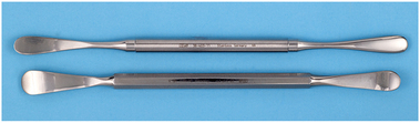
FIGURE 6-8 The Henahan (top) and Seldin (bottom) retractors are broader instruments that provide broader retraction and increased visualization.
The instrument most commonly used to retract the tongue during routine exodontia is the mouth mirror. This is usually part of every basic setup, because it has the usual use for examining the mouth and doing indirect visualization for dental procedures. The mirror can also be used as a tongue or cheek retractor. The Weider tongue retractor is a broad, heart-shaped retractor that is serrated on one side so that it can more firmly engage the tongue and retract it medially and anteriorly (Fig. 6-9, A). When this retractor is used, care must be taken not to position it so far posteriorly that it causes gagging or pushes the tongue into the oropharynx (Fig. 6-9, B).
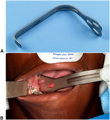
FIGURE 6-9 A, Weider retractor is a large retractor designed to retract tongue. Serrated surface helps to engage tongue so that it can be held securely. B, Weider retractor is used to hold tongue away from surgical field. Austin retractor is used to retract cheek.
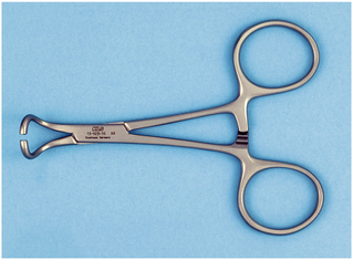
A towel clip (see Fig. 6-28) can also be used to hold the tongue. When a biopsy procedure is to be performed on the posterior aspect of the tongue, the most positive way to control the tongue is by holding the anterior tongue with a towel clip. Local anesthesia must be profound where the clip is placed, and it is wise to mention to the patient that this method of retraction may be used, if anticipated.
GRASPING SOFT TISSUE
Various oral surgical procedures require the surgeon to grasp soft tissue to incise it, stop bleeding or to pass a suture needle. The tissue forceps most commonly used for this purpose are the Adson forceps (pickup; Figure 6-10, A). These are delicate forceps with or without small teeth at the tips, which can be used to hold tissue gently and thereby stabilize it. When this instrument is used, care should be taken not to grasp the tissue too tightly, which will crush the tissue. Toothed forceps allow tissue to be held with a more delicate grip than untoothed forceps.
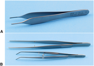
FIGURE 6-10 A, Small, delicate Adson tissue forceps are used to gently stabilize soft tissue for suturing or dissection. B, The Stillies pickup (top) is longer than the Adson pickup and is used to handle tissue in the more posterior aspect of the mouth. The college pliers (bottom) are angled forceps that are used for picking up small objects in the mouth or from the tray stand. The college pliers shown here are the locking version.
When working in the posterior part of the mouth, the Adson forceps may be too short. Longer forceps that have a similar shape are the Stillies forceps. These forceps are usually 7 to 9 inches long and can easily grasp tissue in the posterior part of the mouth and still leave enough of the instrument protruding beyond the lips for the surgeon to hold and control it easily (Fig. 6-10, B).
Occasionally, it is more convenient to have an angled forceps. Such a forceps is the college, or cotton, forceps (see Fig. 6-10, B). Although these forceps are not especially useful for handling tissue, they are an excellent instrument for picking up loose fragments of tooth, amalgam, or other foreign material and for placing or removing gauze packs.
In some types of surgery, especially when removing larger amounts of tissue or doing biopsies, such as in an epulis fissurata, forceps with locking handles and teeth that will grip the tissue firmly are necessary. In this situation the Allis tissue forceps are used (Fig. 6-11, A and B). The locking handle allows the forceps to be placed in the proper position and then to be held by an assistant to provide the necessary tension for proper dissection of the tissue. The Allis forceps should never be used on tissue that is to be left in the mouth because they cause a relatively large amount of tissue destruction as a result of crushing injury (Fig. 6-11, C). However, the forceps can be used to grasp the tongue in a manner similar to a towel clamp.
CONTROLLING HEMORRHAGES
When incisions are made through tissue, small arteries and veins are incised, causing bleeding. For most dentoalveolar surgery, pressure on the wound is usually sufficient to control bleeding. Occasionally, pressure does not stop bleeding from a larger artery or vein. When this occurs, an instrument called a hemostat is useful (Fig. 6-12, A). Hemostats come in a variety of shapes, may be small and delicate or larger, and are straight or curved. The hemostat most commonly used in surgery is a curved hemostat (Fig. 6-12, B).
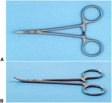
FIGURE 6-12 A, Superior view of hemostat used for oral surgery. B, Oblique view of curved hemostat. Straight hemostats are also available.
A hemostat has long, delicate beaks used to grasp tissue and a locking handle. The locking mechanism allows the surgeon to clamp the hemostat onto a vessel and then let go of the instrument, which will remain clamped onto the tissue. This is useful when the surgeon plans to place a suture around the vessel or cauterize it (use heat to sear the vessel closed).
In addition to its use as an instrument for controlling bleeding, the hemostat is especially useful in oral surgery to remove granulation tissue from tooth sockets and to pick up small root tips, pieces of calculus, amalgam, fragments, and any other small particles that have dropped into the wound or adjacent areas.
REMOVING BONE
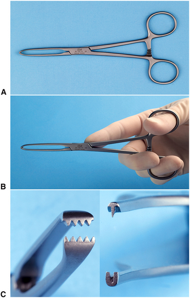
The instrument most commonly used for removing bone in dentoalveolar surgery is the rongeur forceps. This instrument has sharp blades that are squeezed together by the handles, cutting or pinching through the bone. Rongeur forceps have a mechanism incorporated so that when hand pressure is released, the instrument reopens. This allows the surgeon to make repeated bone trimming actions without manually reopening the instrument (Fig. 6-13, A). The two major designs for rongeur forceps are (1) a side-cutting forceps and (2) the side- and end-cutting forceps (Figure 6-13, B).
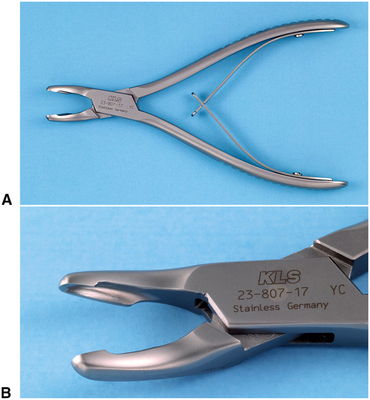
FIGURE 6-13 A, Rongeurs are bone-cutting forceps that have spring-loaded handles. B, Blumenthal rongeurs are combination end-cutting and side-cutting blades. They are preferred for oral surgery procedures.
The side- and end-cutting forceps (Blumenthal rongeurs) are more practical for most dentoalveolar surgical procedures that require bone removal. Because these forceps are end-cutting, they can be inserted into sockets for removal of interradicular bone, and they can also be used to remove sharp edges of bone. Rongeurs can be used to remove large amounts of bone efficiently and quickly. Because rongeurs are delicate instruments, the surgeon should not use the rongeurs to remove large amounts of bone in single bites. Rather, smaller amounts of bone should be removed in multiple bites. Likewise, the rongeurs should never be used to remove teeth, because this practice will quickly dull and destroy the instrument and risks losing the tooth into the throat because rongeurs are not well designed to hold firmly onto an extracted tooth. Rongeurs are usually expensive, so care should be taken to keep them sharp and in working order.
Bur and Handpiece
Another method for removing bone is with a bur in a handpiece. This is the technique that most surgeons use when removing bone for surgical removal of teeth. High-speed, high-torque handpieces with sharp carbide burs remove cortical bone efficiently. Burs such as a No. 557 or No. 703 fissure bur or a No. 8 round burs are used. When large amounts of bone must be removed, such as in torus reduction, a large bone bur that resembles an acrylic bur is used.
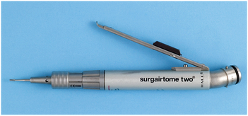
The handpiece that is used must be completely sterilizable. When a handpiece is purchased, the manufacturer’s specifications must be checked carefully to ensure that this is possible. The handpiece should have high speed and torque (Fig. 6-14). This allows the bone removal to be done rapidly and allows efficient sectioning of teeth. The handpiece must not exhaust air into the operative field, making it unwise to use typical high-speed turbine drills for routine restorative dentistry. The reason is that the air exhausted into the wound may be forced into deeper tissue planes and produce tissue emphysema, a dangerous occurrence.
Mallet and Chisel
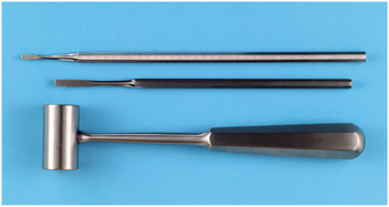
Occasionally, bone removal is performed using a mallet and chisel (Fig. 6-15). The mallet and chisel are often used when removing lingual tori. The edge of the chisel must be kept sharp to function properly. (See Chapter 13.)
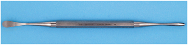
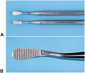
Bone File
Final smoothing of bone before suturing a mucoperiosteal flap back into position is usually performed with a small bone file (Fig. 6-16, A). The bone file is usually a double-ended instrument with a small and large end. The bone file cannot be used efficiently for removal of large amounts of bone; therefore, it is used only for final smoothing. The teeth of many bone files are arranged in such a fashion that they remove bone only on a pull stroke (Fig. 6-16, B). Pushing this type of bone file against bone results only in burnishing and crushing the bone, and should be avoided.
REMOVING SOFT TISSUE FROM BONY CAVITIES
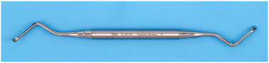
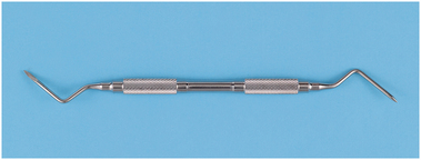
The curette commonly used for oral surgery is an angled, double-ended instrument used to remove soft tissue from bony defects (Fig. 6-17). The principal use is to remove granulomas or small cysts from periapical lesions, but the curette is also used to remove small amounts of granulation tissue debris from a tooth socket. Note that the periapical curette is distinctly different from the periodontal curette in design and function.
SUTURING SOFT TISSUE
Once a surgical procedure has been completed, the mucoperiosteal flap is returned to its original position and is held in place by sutures. The needle holder is the instrument used to place the sutures.
Needle Holder
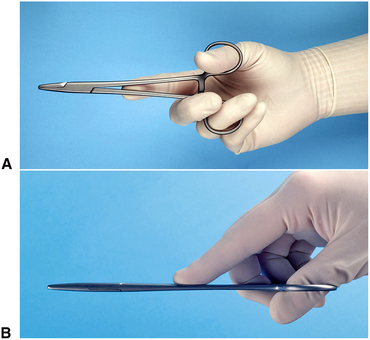
The needle holder is an instrument with a locking handle and a short, blunt beak. For intraoral placement of sutures, a 6-inch (15-cm) needle holder is usually recommended (Fig. 6-18). The beaks of a needle holder are shorter and stronger than the beaks of a hemostat (Fig. 6-19). The face of a beak of the needle holder is crosshatched to permit a positive grasp of the suture needle. The hemostat has parallel grooves on the face of the beaks, thereby decreasing the control over needle and suture. Therefore the hemostat is a poor instrument for suturing.
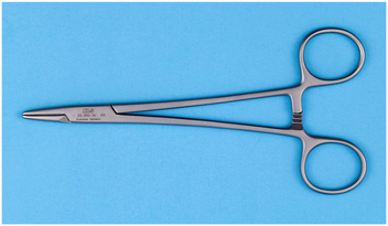
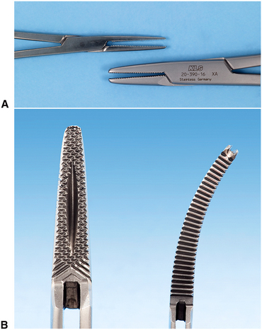
FIGURE 6-19 A, Hemostat (top) has longer, thinner beak compared with needle holder (bottom) and therefore should not be used for suturing. B, Face of shorter beak of needle holder is crosshatched to ensure positive grip on needle (left). Face of hemostat has parallel grooves that do not allow a firm grip on needle (right).
To control the locking handles properly and to direct the long needle holder, the surgeon must hold the instrument in the proper fashion (Fig. 6-20). The thumb and ring finger are inserted through the rings. The index finger is held along the length of the needle holder to steady and direct it. The second finger aids in controlling the locking mechanism. The index finger should not be put through the finger ring because this will result in dramatic decrease in control.
Suture Needle
The needle used in closing mucosal incisions is usually a small half-circle or three-eighths–circle suture needle. The needle is curved to allow it to pass through a limited space, where a straight needle cannot reach, and passage can be done with a twist of the wrist. Suture needles come in a large variety of shapes, from very small to very large (Fig. 6-21, A). The tips of suture needles are either tapered, such as a sewing needle, or they have triangular tips that allow them to be cutting needles. A cutting needle will pass through mucoperiosteum more easily than a tapered needle (Fig. 6-21, B). The cutting portion of the needle extends about one third the length of the needle, and the remaining portion of the needle is round. Tapered needles are used for more delicate tissues such as for ocular or vascular surgery. Care must be taken with cutting needles because they can cut through tissues lateral to the track of the needle if not used carefully and correctly. The suture material is usually purchased already swaged on by the manufacturer.
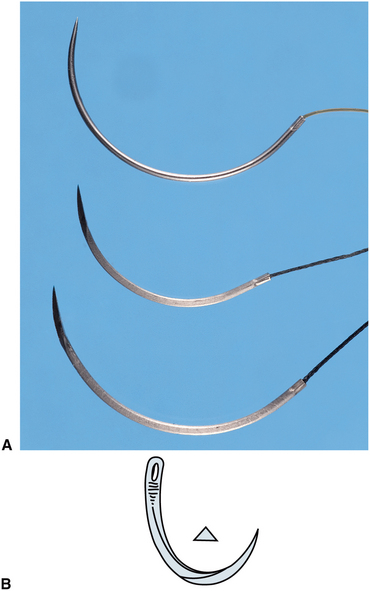
FIGURE 6-21 A, Comparison of needles used in oral surgery. Top is C-17 needle, which is usually 4-0 size suture. Middle is PS-2 needle, and bottom is SH. All are cutting needles, and suture material is swagged onto the needle. B, Tip of needle used to suture mucoperiosteum is triangular in cross section to make it a cutting needle.
The curved needle is held approximately two thirds of the distance between the tip and the base of the needle (Fig. 6-22). This allows enough of the needle to be exposed to pass through the tissue, while allowing the needle holder to grasp the needle in its strong portion to prevent bending of the needle. Techniques for placing sutures are further discussed in Chapter 8.
Suture Material
Many types of suture materials are available. The materials are classified by diameter, resorbability, and whether they are monofilament or polyfilament.
The size of suture relates to its diameter and is designated by a series of zeros. The diameter most commonly used in the suturing of oral mucosa is 3-0 (000). A larger size suture is 2-0, or 0. Smaller sizes are designated, for example, 4-0, 5-0, and 6-0. Sutures of very fine size, such as 6-0, are usually used in conspicuous places on the skin, such as the face, because properly placed smaller sutures usually cause less scarring. Sutures of size 3-0 are large enough to withstand the tension placed on them intraorally and strong enough for easier knot tying with a needle holder compared with smaller-diameter sutures.
Sutures may be resorbable or nonresorbable. Nonresorbable suture materials include types such as silk, nylon, vinyl, and stainless steel. The most commonly used nonresorbable suture in the oral cavity is silk. Nylon, vinyl, and stainless steel are rarely used in the mouth. Resorbable sutures are primarily made of gut. Although the term catgut is often used to designate this type of suture, gut actually is derived from the serosal surface of sheep intestines. Plain catgut resorbs quickly in the oral cavity, rarely lasting longer than 3 to 5 days. Gut that has been treated by tanning solutions (chromic acid) and is therefore called chromic gut lasts longer—up to 7 to 10 days. Several synthetic resorbable sutures are also available. These are materials that are long chains of polymers braided into suture material. Examples are polyglycolic acid and polylactic acid. These materials are slowly resorbed, taking up to 4 weeks before they are resorbed. Such long-lasting resorbable sutures are rarely indicated in the oral cavity for basic oral surgery.
Finally, sutures are classified based on whether they are monofilament or polyfilament. Monofilament sutures are sutures such as plain and chromic gut, nylon, and stainless steel. Polyfilament sutures are silk, polyglycolic acid, and polylactic acid. Sutures that are made of braided material are easy to handle and tie and rarely come untied. The cut ends are usually soft and nonirritating to the tongue and surrounding soft tissues. However, because of the multiple filaments, they tend to “wick” oral fluids along the suture to the underlying tissues. This wicking action may carry bacteria along with the saliva. Monofilament sutures do not cause this wicking action but may be more difficult to tie, tend to come untied, and the cut ends are stiffer and therefore more irritating to the tongue and soft tissues.
One of the most commonly used suture for the oral cavity is 3-0 black silk. The size 3-0 has the appropriate amount of strength; the polyfilament nature of the silk makes it easy to tie and well tolerated by the patient’s soft tissues. The color makes the suture easy to see when the patient returns for suture removal. Sutures that are holding mucosa together usually stay no longer than 5 to 7 days, so the wicking action is of little clinical importance. Many surgeons prefer 3-0 chromic suture to avoid the need to later remove it. (Techniques for suturing and knot tying are presented in Chapter 8.)
Scissors
The final instruments necessary for placing sutures are suture scissors (Fig. 6-23). The suture scissors usually have short cutting edges because their sole purpose is to cut sutures. The most commonly used suture scissors for oral surgery are the Dean scissors. These scissors have slightly curved handles and serrated blades that make cutting sutures easier. Suture scissors usually have long handles and thumb and finger rings. The scissors are held in the same way as the needle holder.
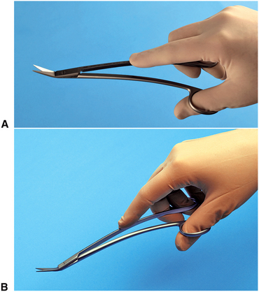
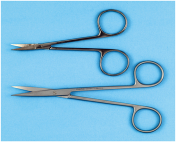
Other types of scissors are designed for cutting soft tissue. The two major types of tissue scissors are the Iris scissors and the Metzenbaum scissors (Fig. 6-24, A). These scissors can have straight or curved blades. The Iris scissors are small, sharp-pointed, delicate tools used for fine work. The Metzenbaum scissors are used for undermining soft tissue and for cutting. They can have either sharp or blunt (rounded) tips. Tissue scissors such as the Iris or Metzenbaum scissors should not be used to cut sutures because the suture material will dull the edges of the blades and make them less effective and more traumatic when cutting tissue. The exception is when removing very fine sutures placed in skin incisions in the face. Scissors with thin, pointed tips such as an Iris may be useful.
HOLDING THE MOUTH OPEN
When performing extractions of mandibular teeth, it is necessary to support the mandible to prevent stress on the temporomandibular joints. Supporting the patient’s jaw on a bite block will protect the joints. The bite block is just what the name implies (Fig. 6-25, A and B). The bite block is a soft, rubberlike block on which the patient can rest the teeth. The patient opens the mouth to a comfortably wide position, and the rubber bite block is inserted, which holds the mouth in the desired position. Bite blocks come in several sizes to fit variously sized patients and produce varying degrees of opening. Should the surgeon need the mouth to open wider using any size of bite block, the patient must open more widely and the bite block must be positioned more to the posterior of the mouth. For most adult patients a pediatric-sized bite block is adequate when placed over the molar teeth.
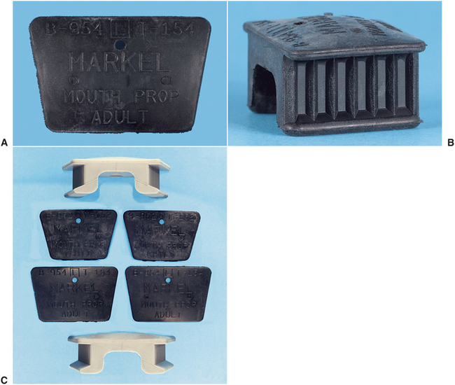
FIGURE 6-25 A, Silicone bite block is used to hold mouth open in position chosen by patient. B, The sides of the bite block are corrugated to provide a surface for the teeth to engage. C, The blocks come in a variety of sizes.
The side-action mouth prop or Molt mouth prop (Fig. 6-26) can be used by the operator to open the mouth wider if necessary. This mouth prop has a ratchet-type action, opening the mouth wider as the handle is closed. This type of mouth prop should be used with caution because great pressure can be applied to the teeth and temporomandibular joint, and injury may occur with injudicious use. This type of mouth prop is useful in patients who are deeply sedated or have mild forms of trismus.
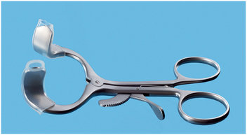
FIGURE 6-26 Side-action, or Molt, mouth prop can be used to open patient’s mouth when patient is unable to cooperate, such as during sedation or has some degree of trismus.
Whenever a bite block or side-action mouth prop is used, the surgeon should take care to avoid opening the mouth too widely because it may cause stress on the jaw joint. Occasionally, this may result in stretch injury to the joint, necessitating additional treatment. When long procedures are being performed, it is a good idea periodically to remove the prop and allow the patient to move the jaw and rest the muscles for a short time.
SUCTIONING
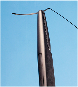
To provide adequate visualization, blood, saliva, and irrigating solutions must be suctioned from the operative site. The surgical suction is one that has a smaller orifice than the type used in general dentistry to more rapidly evacuate fluids from the surgical site to maintain adequate visualization. Many of these suctions are designed with several orifices so that the soft tissue will not become aspirated into the suction hole and cause tissue injury (Fig. 6-27, A).
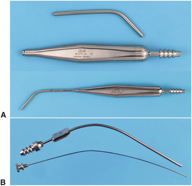
FIGURE 6-27 A, Typical surgical suction has small-diameter tip. Suction tips usually have a hole to prevent tissue injury caused by excess suction pressure. Top is unassembled for cleaning; bottom is assembled for use. B, Fraser suction tip has blade in handle to allow operator more control over amount of suction power. Holding the thumb over the hole increases suction at the tip. Wire stylet is used to clean tip when bone or tooth particles plug suction.
The Fraser suction has a hole in the handle portion that can be covered as needed. When hard tissue is being cut under copious irrigation, the hole is covered so that the solution is removed rapidly. When soft tissue is being suctioned, the hole can be left uncovered to prevent tissue injury or soft tissue obstruction of the suction tip (Fig. 6-27, B).
HOLDING TOWELS AND DRAPES IN POSITION
When drapes are placed around a patient, they can be held together with a towel clip (Fig. 6-28). This instrument has a locking handle and finger and thumb rings. The action ends of the towel clip can be sharp or blunt. Those with curved points penetrate the towels and drapes. When this instrument is used, the operator must exercise extreme caution not to pinch the patient’s underlying skin.
IRRIGATING
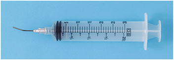
When a handpiece and bur are used to remove bone, it is essential that the area be irrigated with a steady stream of irrigating solution, usually sterile saline or sterile water. The irrigation cools the bur and prevents bone-damaging heat buildup. The irrigation also increases the efficiency of the bur by washing away bone chips from the flutes of the bur and by providing a certain amount of lubrication. In addition, once a surgical procedure is completed and before the mucoperiosteal flap is sutured back into position, the surgical field should be thoroughly irrigated. A large plastic syringe with a blunt 18-gauge needle is commonly used for irrigation. Although the syringe is disposable, it can be sterilized multiple times before it must be discarded. The needle should be blunt and smooth so that it does not damage soft tissue, and it should be angled for more efficient direction of the irrigating stream (Fig. 6-29).
EXTRACTING TEETH
One of the most important instruments used in the extraction procedure is the dental elevator. These instruments are used to luxate teeth (loosen them) from the surrounding bone. Loosening teeth before the application of the dental forceps makes extractions easier. By elevating the teeth before the application of the forceps, the clinician can minimize the incidence of broken roots, teeth, and bone. Finally, luxation of teeth before forceps application facilitates the removal of a broken root should it occur, because the prior elevator use is likely to loosen the root in the dental socket. In addition to their role in loosening teeth from the surrounding bone, dental elevators are also used to expand alveolar bone. By expanding the buccocervical plate of bone, the surgeon facilitates the removal of a tooth that has a limited and obstructed path for removal. Finally, elevators are used to remove broken or surgically sectioned roots from their sockets.
Dental Elevators
The three major components of the elevator are the handle, shank, and blade (Fig. 6-30). The handle of the elevator is usually of generous size, so it can be held comfortably in the hand to apply substantial but controlled force. The application of specifically applied force is critical in the proper use of dental elevators. In some situations, cross bar or T-bar handles are used. These instruments must be used with great caution because they can generate an excessive amount of force (Fig. 6-31).
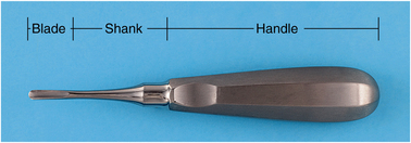
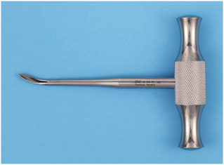
FIGURE 6-31 Cross bar handle is used on certain elevators. This type of handle can generate large amounts of force and therefore must be used with great caution.
The shank of the elevator simply connects the handle to the working end, or blade, of the elevator. The shank is generally of substantial size and is strong enough to transmit the force from the handle to the blade. The blade of the elevator is the working tip of the elevator and is used to transmit the force to the tooth, bone, or both.
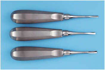
Types of Elevators
The biggest variation in the type of elevator is in the shape and size of the blade. The three basic types of elevators are (1) the straight type; (2) the triangle or pennant-shape type; and (3) the pick type. The straight elevator is the most commonly used elevator to luxate teeth (Fig. 6-32, A). The blade of the straight elevator has a concave surface on one side that is placed toward the tooth to be elevated (Fig. 6-32, B). The small straight elevator, No. 301, is frequently used for beginning the luxation of an erupted tooth, before application of the forceps (Fig. 6-33). Larger straight elevators are used to displace roots from their sockets and are also used to luxate teeth that are more widely spaced or once a smaller-sized straight elevator becomes less effective. The most commonly used large straight elevator is the No. 34S, but the No. 46 and No. 77R are also used occasionally.
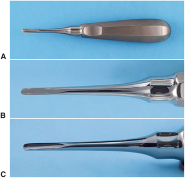
FIGURE 6-32 A, Straight elevators are most commonly used elevators. B and C, Blade of straight elevator is concave on its working side.
The shape of the blade of the straight elevator can be angled from the shank, allowing this instrument to be used in the more posterior aspects of the mouth. Two examples of the angled-shank elevator with a blade similar to the straight elevator are the Miller elevator and the Potts elevator.
The second most commonly used type of elevator is the triangular elevator (Fig. 6-34). These elevators are provided in pairs: a left and a right. The triangular elevator is most useful when a broken root remains in the tooth socket and the adjacent socket is empty. A typical example would be when a mandibular first molar is fractured, leaving the distal root in the socket but the mesial root removed with the crown. The tip of the triangular elevator is placed into the socket, with the shank of the elevator resting on the buccal plate of bone. The elevator is then turned in a wheel-and-axle rotation, with the sharp tip of the elevator engaging the cementum of the remaining distal root; the elevator is then turned and the root is delivered. Triangular elevators come in a variety of types and angulations, but the Cryer is the most common type.
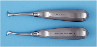
FIGURE 6-34 Triangular elevators (Cryer) are pairs of instruments and are therefore used for mesial or distal roots.
The third type of elevator that is used with some frequency is the pick-type elevator. This type of elevator is used to remove roots. The heavy version of the pick is the Crane pick (Fig. 6-35). This instrument is used as a lever to elevate a broken root from the tooth socket. Usually it is necessary to drill a hole with a bur (purchase point) approximately 3 mm deep into the root just at the bony crest. The tip of the pick is then inserted into the hole, and with the buccal plate of bone as a fulcrum, the root is elevated from the tooth socket. Occasionally the sharp point can be used without preparing a purchase point by engaging the cementum or furcation of the tooth.
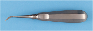
FIGURE 6-35 Crane pick is a heavy instrument used to elevate whole roots or even teeth after purchase point has been prepared with bur.
The second type of pick is the root tip pick or apex elevator (Fig. 6-36). The root tip pick is a delicate instrument that is used to tease small root tips from their sockets. It must be emphasized that this is a thin instrument and should not be used as a wheel-and-axle or lever type of elevator like the Cryer elevator or the Crane pick. The root tip pick is used to tease the very small root end of a tooth by inserting the tip into the periodontal ligament space between the root tip and socket wall.
Extraction Forceps
The extraction forceps are instruments used for removing the tooth from the alveolar bone. These forceps are designed in many styles and configurations to adapt to the variety of teeth for which they are used. Each basic design offers a multiplicity of variations to coincide with individual operator preferences. This section deals with the basic fundamental designs and touches on several of the variations.
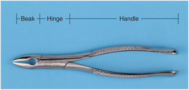
Forceps Components
The basic components of dental extraction forceps are the handle, hinge, and beaks (Fig. 6-37). The handles are usually of adequate size to be handled comfortably and deliver sufficient pressure and leverage to remove the required tooth. The handles have a serrated surface to allow a positive grip and to prevent slippage.
The handles of the forceps are held differently, depending on the position of the tooth to be removed. Maxillary forceps are held with the palm underneath the forceps so that the beak is directed in a superior direction (Fig. 6-38). The forceps used for removal of mandibular teeth are held with the palm on top of the forceps so that the beak is pointed down toward the teeth (Fig. 6-39). The handles of the forceps are usually straight but may be curved. This provides the operator with a sense of better fit (Fig. 6-40).
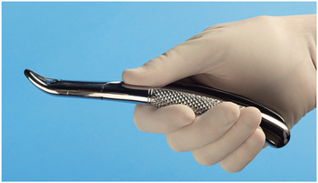
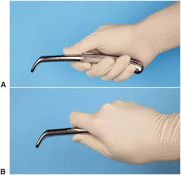
FIGURE 6-39 A, Forceps used to remove mandibular teeth are held with palm on top of forceps. B, Firmer grip for delivering greater amounts of rotational force can be achieved by moving thumb around and under handle.
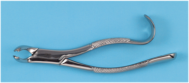
FIGURE 6-40 Straight handles are usually preferred, but curved handles are preferred by some surgeons.
The hinge of the forceps, like the shank of the elevator, is merely a mechanism for connecting the handle to the beak. The hinge transfers and concentrates the force applied to the handles to the beak. One distinct difference in styles does exist: The usual American type of forceps has a hinge in a horizontal direction and is used as has been described (see Fig. 6-37). The English preference is for a vertical hinge and corresponding vertically positioned handle (Fig. 6-41, A). Thus the English-style handle and hinge are used with the hand held in a vertical direction as opposed to a horizontal direction (Fig. 6-41, B).
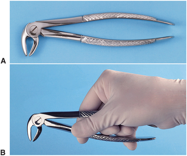
FIGURE 6-41 A, English style of forceps has hinge in vertical direction. B, English style of forceps is held in vertical direction.
The beaks of the extraction forceps are the source of the greatest variation among forceps. The beak is designed to adapt to the tooth root near the junction of the crown and root. One must remember that the beaks of the forceps are designed to be adapted to the root structure of the tooth and not to the crown of the tooth. In a sense then, different beaks are designed for single-rooted teeth, two-rooted teeth, and three-rooted teeth. The design variation is such that the tips of the beaks will adapt closely to the various root formations, improving the surgeon’s control of forces on the root and decreasing the chance for root fracture. The more closely the beaks of the forceps adapt to the tooth roots, the more efficient the extraction and the less chance for undesired outcomes.
A final design variation is in the width of the beak. Some forceps beaks are narrow because their primary use is to remove narrow teeth, such as incisor teeth. Other forceps beaks are broader because the teeth they are designed to remove are substantially wider, such as lower molar teeth. Forceps designed to remove a lower incisor can theoretically be used to remove a lower molar, but the beaks are so narrow that they will be inefficient for that application. Similarly, the broader molar forceps will not adapt to the narrow space occupied by the lower incisor and therefore cannot be used in that situation without damage to adjacent teeth.
The beaks of forceps are angled so that they can be placed parallel to the long axis of the tooth, with the handle in a comfortable position. Therefore the beaks of maxillary forceps are usually parallel to the handles. Maxillary molar forceps are offset in a bayonet fashion to allow the operator to reach the posterior aspect of the mouth comfortably and yet keep the beaks parallel to the long axis of the tooth. The beaks of mandibular forceps are usually set perpendicular to the handles, which allows the surgeon to reach the lower teeth and maintain a comfortable, controlled position.
Maxillary Forceps
The removal of maxillary teeth requires the use of instruments designed for single-rooted teeth and for teeth with three roots. The maxillary incisors, canine teeth, and premolar teeth are considered to be single-rooted teeth. The maxillary first premolar frequently has a bifurcated root, but because this occurs in the apical one third, it has no influence on the design of the forceps. The maxillary molars have trifurcated roots, and there are extraction forceps that will adapt to that configuration.
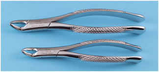
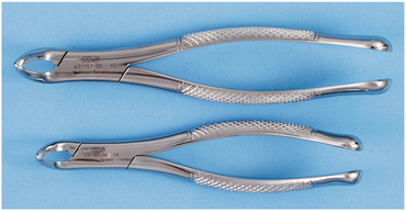
After some elevation, the single-rooted maxillary teeth are usually removed with maxillary universal forceps, usually No. 150 (Fig. 6-42). The No. 150 forceps are slightly S-shaped when viewed from the side and are essentially straight when viewed from above. The beaks of the forceps curve to meet only at the tip. The slight curve of the No. 150 allows the operator to reach not only the incisors but also the premolars comfortably. The beak of the No. 150 forceps comes in a style that has been modified slightly to form the No. 150A forceps (Fig. 6-43). The No. 150A is useful for the maxillary premolar teeth and should not be used for the incisors because its adaptation to the roots of the incisors is poor.
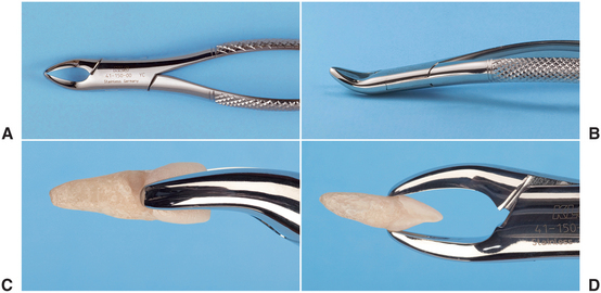
FIGURE 6-42 A, Superior view of No. 150 forceps. B, Side view of No. 150 forceps. C and D, No. 150 forceps adapted to maxillary central incisor.
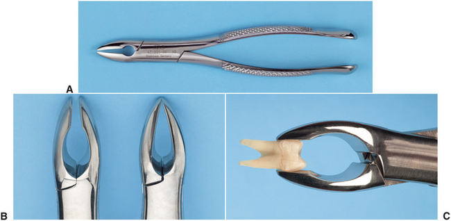
FIGURE 6-43 A, Superior view of No. 150A forceps. B, No. 150A forceps have parallel beaks that do not touch in distinction from 150 forceps beak. C, Adaptation of No. 150A forceps to maxillary premolar.
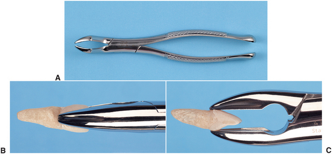
In addition to the No. 150 forceps, straight forceps are also available. The No. 1 forceps (Fig. 6-44), which can be used for maxillary incisors and canines, are easier to use than the No. 150 for upper incisors.
The maxillary molar teeth are three-rooted teeth with a single palatal root and a buccal bifurcation. Therefore, forceps that are specifically adapted to fit the maxillary molars must have a smooth, concave surface for the palatal root and a beak with a pointed design that will fit into the buccal bifurcation. This requires that the molar forceps come in pairs: a left and a right. Additionally, the molar forceps should be offset so that the surgeon can reach the posterior aspect of the mouth and remain in the correct position. The most commonly used molar forceps are the No. 53 right and left (Fig. 6-45). These forceps are designed to fit anatomically around the palatal beak, and the pointed buccal beak fits into the buccal bifurcation. The beak is offset to allow for good surgeon positioning.
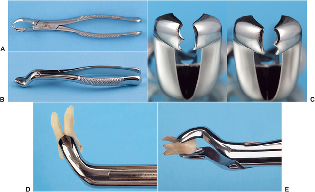
FIGURE 6-45 A, Superior view of the No. 53L forceps. B, Oblique view of No. 53L forceps. C, Right, No. 53L; left, No. 53R. D and E, No. 53L adapted to maxillary molar.
A design variation is shown in the No. 88 right and left forceps, which have a longer, more accentuated, pointed beak formation (Fig. 6-46). These forceps are known as upper cowhorn forceps. They are particularly useful for maxillary molars with crowns that are severely carious. The sharply pointed beaks may reach deeper into the trifurcation to sound dentin. The major disadvantage is that they crush crestal alveolar bone, and when used on intact teeth without due caution, fracture of large amounts of buccal alveolar bone may occur.
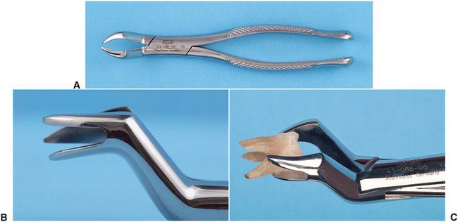
FIGURE 6-46 A, Superior view of No. 88L forceps. B, Side view of No. 88L forceps. C, No. 88R adapted to maxillary molar.
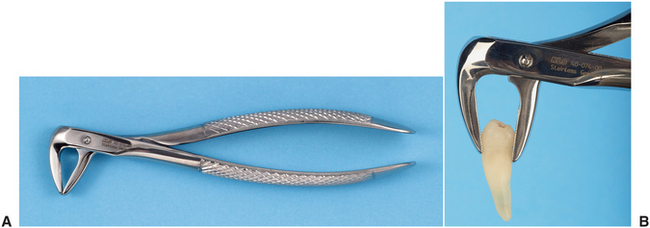
On occasion, maxillary second molars and erupted third molars have a single conical root. In this situation, forceps with broad, smooth beaks that are offset from the handle can be useful. The No. 210S forceps exemplify this design (Fig. 6-47). Another design variation is shown in the offset molar forceps with very narrow beaks. These forceps are used primarily to remove broken maxillary molar roots but can be used for removal of narrow premolars and for lower incisors. These forceps, the No. 65, are also known as root tip forceps (Fig. 6-48).
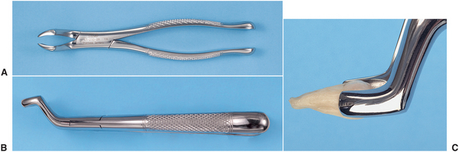
FIGURE 6-47 A, Superior view of No. 210S forceps. B, Side view of No. 210S forceps. C, No. 210S adapted to maxillary molar.
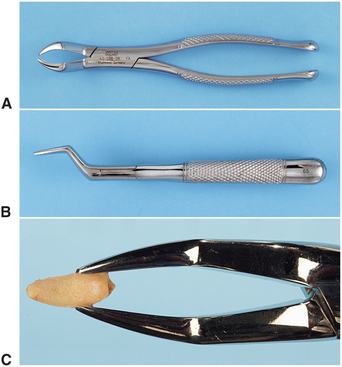
FIGURE 6-48 A, Superior view of No. 65 forceps. B, Side view of No. 65 forceps. C, No. 65 adapted to broken root.
A smaller version of the No. 150, the No. 150S, is useful for removing primary teeth (Fig. 6-49). These forceps adapt well to all maxillary primary teeth and can be used as universal primary tooth forceps.
Mandibular Forceps
Extraction of mandibular teeth requires forceps that can be used for single-rooted teeth for the incisors, canines, and premolars, as well as for two-rooted teeth for the molars. The forceps most commonly used for the single-rooted teeth are the lower universal forceps, or the No. 151 (Fig. 6-50). These forceps have handles similar in shape to the No. 150, but the beaks are pointed inferiorly for the lower teeth. The beaks are smooth and narrow and meet only at the tip. This allows the beaks to fit near the cervical line of the tooth and to grasp the root.
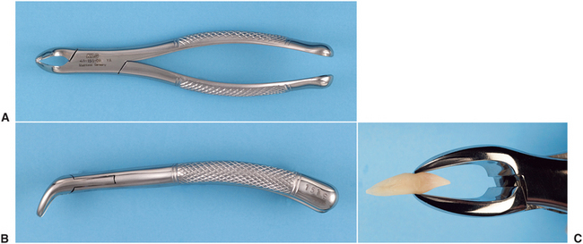
FIGURE 6-50 A, Superior view of No. 151 forceps. B, Side view of No. 151 forceps. C, No. 151 forceps adapted to mandibular incisor.
The No. 151A forceps have been modified slightly for mandibular premolar teeth (Fig. 6-51). These forceps should not be used for other lower teeth because their form prevents adaptation to the roots of the teeth.
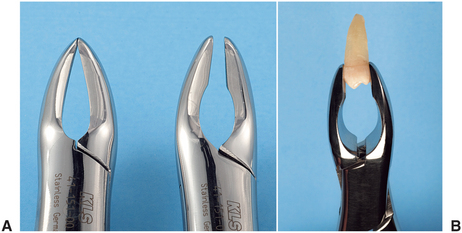
FIGURE 6-51 A, No. 151A forceps have beaks that are parallel and do not adapt well to roots of most teeth in contradistinction to the No. 151 forceps beaks. B, No. 151A forceps adapted to a lower premolar tooth. The lack of close adaptation of tips of beak to root of tooth is visualized.
The English style of vertical-hinge forceps can be used for the single-rooted teeth in the mandible (Fig. 6-52). Great force can be generated with these forceps. Unless great care is used, the incidence of root fracture is high with this instrument. Therefore, it is rarely used by the inexperienced, beginning surgeon.
The mandibular molars are bifurcated, two-rooted teeth that allow the use of forceps that anatomically adapt to the tooth. Because the bifurcation is on the buccal and the lingual sides, only a single molar forceps are necessary for the both sides, in contradistinction to the maxilla, for which a right- and left-paired molar forceps set is required.
A useful lower molar forceps are the No. 17 (Fig. 6-53). These forceps are usually straight-handled, and the beaks are set obliquely downward. The beaks have pointed tips in the center to be set into the bifurcation of lower molar teeth. The remainder of the beak adapts well to the sides of the furcation. Because of the pointed tips, the No. 17 forceps cannot be used for molar teeth, which have fused, conical roots. For this purpose the No. 151 forceps are used.
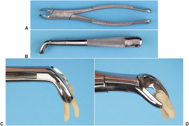
FIGURE 6-53 A, Superior view of No. 17 molar forceps. B, Side view of No. 17 molar forceps. C and D, No. 17 forceps adapted to lower molar.
A major design variation in lower molar forceps is the No. 87, the so-called cowhorn forceps (Fig. 6-54). These instruments are designed with two pointed, heavy beaks that enter into the bifurcation of lower molars. After the forceps are seated into the correct position, usually while pumping the handles up and down, the tooth is actually elevated by squeezing the handles of the forceps together tightly. As beaks are squeezed into the bifurcation, they use the buccal and lingual cortical plates as fulcrums, and the tooth can be literally squeezed out of the socket. As with the English style of forceps, improper use of cowhorn forceps can result in an increase in the incidence of untoward effects, such as fractures of the alveolar bone or damage to maxillary teeth if the forceps are not properly controlled by the surgeon as the molar exits the socket. The beginning surgeon should therefore use cowhorn forceps with caution.
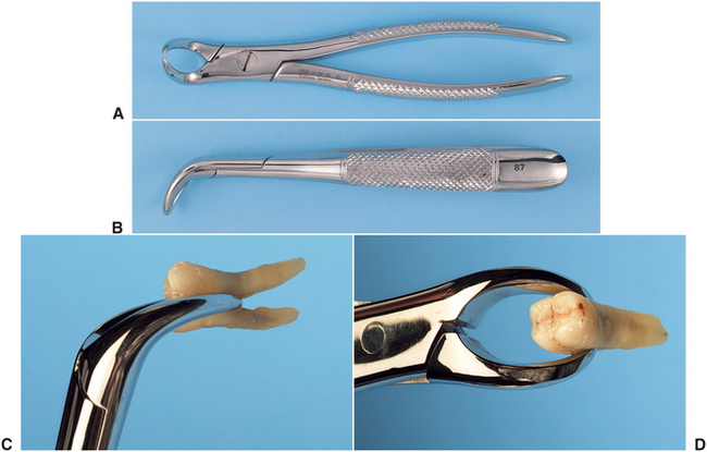
FIGURE 6-54 A, Superior view of cowhorn No. 87 forceps. B, Side view of cowhorn forceps. C and D, Cowhorn forceps adapted to lower molar tooth.
The No. 151 is also adapted for primary teeth. The No. 151S is the same general design as the No. 151 but is scaled down to adapt to the primary teeth. These forceps are adequate for removal of all primary mandibular teeth (Fig. 6-55).
INSTRUMENT TRAY SYSTEMS
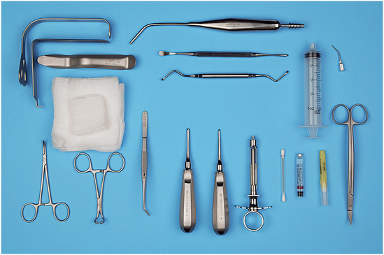
Many dentists find it practical to use the tray method to assemble instruments. Standard sets of instruments are packaged together, sterilized, and then unwrapped at surgery. The typical basic extraction pack includes a local anesthesia syringe, a needle, a local anesthesia cartridge, a No. 9 periosteal elevator, a periapical curette, a small and large straight elevator, a pair of college pliers, a curved hemostat, a towel clip, an Austin or Minnesota retractor, a suction tip, and 2 × 2-inch or 4 × 4-inch gauze (Fig. 6-56). The required forceps would be added to this tray.
A tray used for surgical extractions would include the items from the basic extraction tray plus a needle holder and suture, a pair of suture scissors, a blade handle and blade, Adson tissue forceps, a bone file, a tongue retractor, a pair of Cryer elevators, a rongeur, and a handpiece and bur (Fig. 6-57). These instruments permit incision and reflection of soft tissue, removal of bone, sectioning of teeth, retrieval of roots, débridement of the wound, and suturing of the soft tissue.

FIGURE 6-57 Surgical extraction tray adds necessary instrumentation to reflect soft tissue flaps, remove bone, section teeth, retrieve roots, and suture flaps back into position.
The biopsy tray includes the basic tray minus the elevators, plus a blade handle and blade, needle holder and suture, suture scissors, Metzenbaum scissors, Allis tissue forceps, Adson tissue forceps, and curved hemostat (Fig. 6-58). These instruments permit incision and dissection of a soft tissue specimen and closure of the wound with sutures.
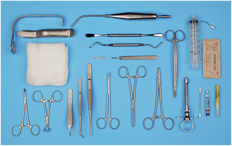
FIGURE 6-58 Biopsy tray adds equipment necessary to remove soft tissue specimen and suture wound closed.
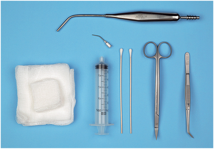
The postoperative tray has the necessary instruments to irrigate the surgical site and remove sutures (Fig. 6-59). The tray usually includes scissors, college pliers, an irrigation syringe, cotton applicator sticks, gauze, and suction tip.
The instruments may be placed on a flat tray, wrapped with sterilization paper, and sterilized. When ready for use, the tray is taken to the operatory and opened in a manner to preserve instrument sterility, and the instruments are used from the tray. This system requires a large autoclave to accommodate the tray.
Alternately, metal cassettes can be used instead of a tray. Cassettes are more compact but must also be wrapped in sterilization paper.
The appendix includes prices for the instruments listed for these trays. A casual review of the cost of the surgical instruments will reflect why the surgeon and staff should make every effort to take good care of instruments.