Projection Geometry
Aconventional radiograph is a two-dimensional projection image of a three-dimensional object. In such an image the entire volume of tissue between the x-ray source and the film or digital receptor is projected onto a two-dimensional image. To obtain the maximal value from a radiograph, a clinician must have a clear understanding of normal anatomy and then mentally reconstruct a three-dimensional image of the anatomic structures of interest from one or more of these two-dimensional views. Using high-quality radiographs greatly facilitates this task. The principles of projection geometry describe the effect of focal spot size and position (relative to the object and the film) on image clarity, magnification, and distortion. Clinicians use these principles to maximize image clarity, minimize distortion, and localize objects in the image field. Later chapters will consider different forms of tomographic imaging techniques that produce slices through tissue rather than projection images.
Image Sharpness and Resolution
Several geometric considerations contribute to image clarity, particularly image sharpness and resolution. Sharpness measures how well a boundary between two areas of differing radiodensity is revealed. Image spatial resolution measures how well a radiograph is able to reveal small objects that are close together. Although sharpness and resolution are two distinct features, they are interdependent, being influenced by the same geometric variables. For clinical diagnosis it is desirable to optimize conditions that will result in images with high sharpness and resolution.
When x rays are produced at the target in an x-ray tube, they originate from all points within the area of the focal spot. Because these rays originate from different points and travel in straight lines, their projections of a feature of an object do not occur at exactly the same location on a film. As a result, the image of the edge of an object is slightly blurred rather than sharp and distinct. Figure 4-1 shows the path of photons that originate at the margins of the focal spot and provide an image of the edges of an object. The resulting blurred zone of unsharpness on an image causes a loss in image clarity by reducing sharpness and resolution. The larger the focal spot area, the greater the loss of clarity.
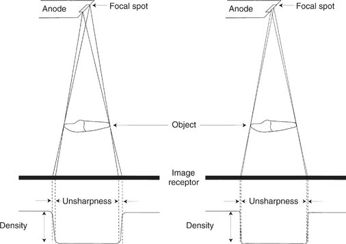
FIG. 4-1 Photons originating at different places on the focal spot result in a zone of unsharpness on the radiograph. The density of the image changes from a high background value to a low value in the area of an edge of enamel, dentin, or bone. On the left a large focal spot size results in a wide zone of unsharpness compared with a small focal spot size on the left that results in a narrow zone of unsharpness.
Three methods exist for minimizing this loss of image clarity and improving the quality of radiographs:
1. Use as small an effective focal spot as practical. Dental x-ray machines should have a nominal focal spot size of 1.0 mm or less. Some tubes used in extraoral radiography have effective focal spots measuring 0.3 mm, which greatly adds to image clarity. X-ray tube manufacturers use as small an effective focal spot size as is consistent with the requirements for heat dissipation. As described in Chapter 1, the size of the effective focal spot is a function of the angle of the target with respect to the long axis of the electron beam. A large angle distributes the electron beam over a larger surface and decreases the heat generated per unit of target area, thus prolonging tube life. However, this results in a larger effective focal spot and loss of image clarity (Fig. 4-2). A small angle has a greater wearing effect on the target but results in a smaller effective focal spot, decreased unsharpness, and increased image sharpness and resolution. This angle of the face of the target to the central x-ray beam is usually between 10 and 20 degrees.
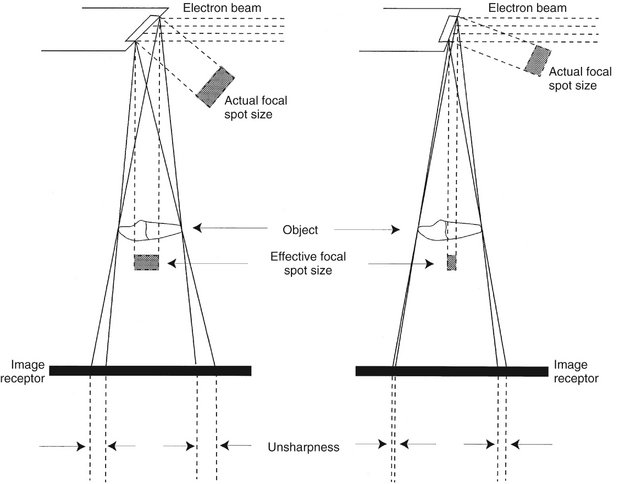
FIG. 4-2 Decreasing the angle of the target perpendicular to the long axis of the electron beam decreases the actual focal spot size and decreases heat dissipation and thereby tube life. It also decreases the effective focal spot size, thus increasing the sharpness of the image.
2. Increase the distance between the focal spot and the object by using a long, open-ended cylinder. Figure 4-3 shows how increasing the focal spot-to-object distance reduces image blurring by reducing the divergence of the x-ray beam. The longer focal spot-to-object distance minimizes blurring by using photons whose paths are almost parallel. The benefits of using a long focal spot-to-object distance support the use of long, open-ended cylinders as aiming devices on dental x-ray machines.
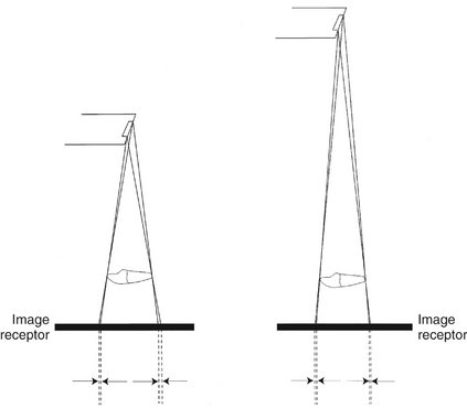
FIG. 4-3 Increasing the distance between the focal spot and the object results in an image with increased sharpness and less magnification of the object.
3. Minimize the distance between the object and the film. Figure 4-4 shows that, as the object-to-film distance is reduced, the unsharpness decreases, resulting in enhanced image clarity. This is the result of minimizing the divergence of the x-ray photons.
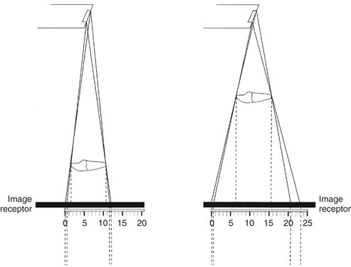
Image Size Distortion
Image size distortion (magnification) is the increase in size of the image on the radiograph compared with the actual size of the object. The divergent paths of photons in an x-ray beam cause enlargement of the image on a radiograph. Image size distortion results from the relative distances of the focal spot-to-film and object-to-film (see Figs. 4-3 and 4-4). Accordingly, increasing the focal spot-to-film distance and decreasing the object-to-film distance minimizes image magnification. The use of a long, open-ended cylinder as an aiming device on an x-ray machine thus reduces the magnification of images on a periapical view. Furthermore, as previously mentioned, this technique also improves image clarity by increasing the distance between the focal spot and the object.
Image Shape Distortion
Image shape distortion is the result of unequal magnification of different parts of the same object. This situation arises when not all the parts of an object are at the same focal spot-to-object distance. The physical shape of the object may often prevent its optimal orientation, resulting in some shape distortion. Such a phenomenon is seen by the differences in appearance of the image on a radiograph compared with the true shape. To minimize shape distortion, the practitioner should make an effort to align the tube, object, and film carefully according to the following guidelines:
1. Position the film parallel to the long axis of the object. Image shape distortion is minimized when the long axes of the film and tooth are parallel. Figure 4-5 shows that the central ray of the x-ray beam is perpendicular to the film but the object is not parallel to the film. The resultant image is distorted because of the unequal distances of the various parts of the object from the film. This type of shape distortion is called foreshortening because it causes the radiographic image to be shorter than the object. Figure 4-6 shows the situation when the x-ray beam is oriented at right angles to the object but not to the film. This results in elongation, with the object appearing longer on the film than its actual length.
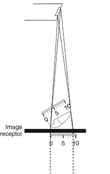
FIG. 4-5 Foreshortening of a radiographic image results when the central ray is perpendicular to the film but the object is not parallel with the film.
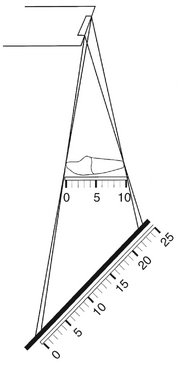
FIG. 4-6 Elongation of a radiographic image results when the central ray is perpendicular to the object but not to the film.
2. Orient the central ray perpendicular to the object and film. Image shape distortion occurs if the object and film are parallel but the central ray is not directed at right angles to each. This is most evident on maxillary molar projections (Fig. 4-7). If the central ray is oriented with an excessive vertical angulation, the palatal roots appear disproportionately longer than the buccal roots.
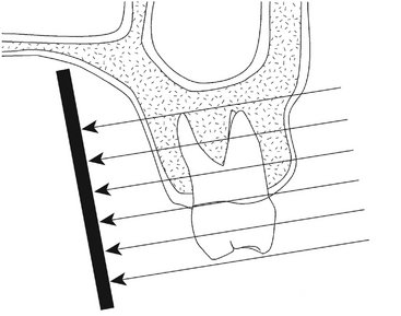
FIG. 4-7 The central ray should be perpendicular to the long axes of both the tooth and the film. If the direction of the x-ray beam is not at right angles to the long axis of the tooth, then the appearance of the tooth is distorted, as seen by apparent elongation of the length of the palatal roots. Additionally, distortion of the relationship of the height of the alveolar crest relative to the cementoenamel junction occurs. In this case the buccal alveolar crest appears to lie superior to the palatal cementoenamel junction.
The practitioner can prevent distortion errors by aligning the object and film parallel with each other and the central ray perpendicular to both.
Paralleling and Bisecting-Angle Techniques
From the earliest days of dental radiography, a clinical objective has been to produce accurate images of dental structures that are normally visually obscured. An early method for aligning the x-ray beam and film with the teeth and jaws was the bisecting-angle technique (Fig. 4-8). In this method the film is placed as close to the teeth as possible without deforming it. However, when the film is in this position, it is not parallel to the long axes of the teeth. This arrangement inherently causes distortion. Nevertheless, by directing the central ray perpendicular to an imaginary plane that bisects the angle between the teeth and the film, the practitioner can make the length of the tooth’s image on the film correspond to the actual length of the tooth. This angle between a tooth and the film is especially apparent when teeth are radiographed in the maxilla or anterior mandible. Although the projected length of a tooth is correct, the image is still distorted because the film and object are not parallel and the x-ray beam is not directed at right angles to them. This distortion tends to increase along the image toward the apex.
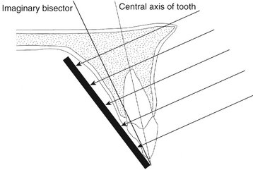
FIG. 4-8 In the bisecting-angle technique the central ray is directed at a right angle to the imaginary plane that bisects the angle formed by the film and the central axis of the object. This method results in an image that is the same length as the object.
When the central ray is not perpendicular to the bisector plane, the length of the image of a projected tooth changes. If the central ray is directed at an angle that is more positive than perpendicular to the bisector, the image of the tooth is foreshortened. Likewise, if it is inclined with more negative angulation to the bisector, the image is elongated. In recent years, the bisecting-angle technique has been used less frequently for general periapical radiography as use of the paralleling technique has increased.
The paralleling technique is the preferred method for making intraoral radiographs. It derives its name as the result of placing the film parallel to the long axis of the tooth (Fig. 4-9). This procedure minimizes image distortion and best incorporates the imaging principles described in the first three sections of this chapter.
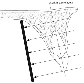
FIG. 4-9 In the paralleling technique the central ray is directed at a right angle to the central axes of the object and the film.
To achieve this parallel orientation, the practitioner often must position the film toward the middle of the oral cavity, away from the teeth. Although this allows the teeth and film to be parallel, it results in some image magnification and loss of definition by increasing unsharpness. As a consequence, the paralleling technique also uses a relatively long open-ended aiming cylinder (“cone”) to increase the focal spot-to-object distance. This directs only the most central and parallel rays of the beam to the film and teeth and reduces image magnification while increasing image sharpness and resolution. The paralleling technique has benefited from the development of fast-speed film emulsions, which allow relatively short exposure times in spite of an increased target-to-object distance.
Because it is desirable to position the film near the middle of the oral cavity with the paralleling technique, film holders should be used to support the film in the patient’s mouth. Chapter 9 discusses film-holding instruments and techniques for intraoral radiography with the paralleling technique.
Object Localization
In clinical practice, the dentist must often derive from a radiograph three-dimensional information concerning patients. The dentist may wish to use radiographs, for example, to determine the location of a foreign object or an impacted tooth within the jaw. Two methods are frequently used to obtain such three-dimensional information. The first is to examine two films projected at right angles to each other. The second method is to use the so-called tube shift technique.
Figure 4-10 shows the first method, in which two projections taken at right angles to one another localize an object in or about the maxilla in three dimensions. In clinical practice the position of an object on each radiograph is noted relative to the anatomic landmarks. This allows the observer to determine the position of the object or area of interest. For example, if a radiopacity is found near the apex of the first molar on a periapical radiograph, the dentist may take an occlusal projection to identify its mediolateral position. The occlusal film may reveal a calcification in the soft tissues located laterally or medially to the body of the mandible. This information is important in determining the treatment required. The right-angle (or cross-section) technique is best for the mandible. On a maxillary occlusal projection the superimposition of features in the anterior part of the skull may frequently obscure the area of interest.
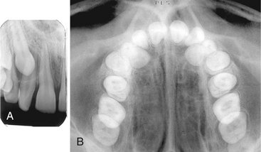
FIG. 4-10 A, The periapical radiograph shows impacted canine lying apical to roots of lateral incisor and first premolar. B, The vertex occlusal view shows that the canine lies palatal to the roots of the lateral incisor and first premolar.
The second method used to identify the spatial position of an object is the tube shift technique. Other names for this procedure are the buccal object rule and Clark’s rule (Clark described it in 1910). The rationale for this procedure derives from the manner in which the relative positions of radiographic images of two separate objects change when the projection angle at which the images were made is changed.
Figure 4-11 shows two radiographs of an object exposed at different angles. Compare the position of the object in question on each radiograph with the reference structures. If the tube is shifted and directed at the reference object (e.g., the apex of a tooth) from a more mesial angulation and the object in question also moves mesially with respect to the reference object, the object lies lingual to the reference object.
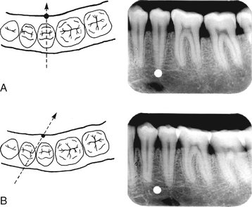
FIG. 4-11 The position of an object may be determined with respect to reference structures with use of the tube shift technique. In A, an object on the lingual surface of the mandible may appear apical to the second premolar. When another radiograph is made of this region angulated from the mesial, B, the object appears to have moved mesially with respect to the second premolar apex (“same lingual” in the acronym SLOB).
Alternatively, if the tube is shifted mesially and the object in question appears to move distally, it lies on the buccal aspect of the reference object (Fig. 4-12). These relationships can be easily remembered by the acronym SLOB: Same Lingual, Opposite Buccal. Thus, if the object in question appears to move in the same direction with respect to the reference structures as does the x-ray tube, it is on the lingual aspect of the reference object; if it appears to move in the opposite direction as the x-ray tube, it is on the buccal aspect. If it does not move with respect to the reference object, it lies at the same depth (in the same vertical plane) as the reference object.
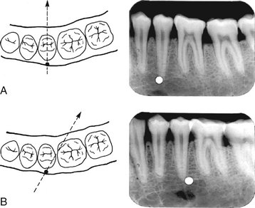
FIG. 4-12 The position of an object can be determined with respect to reference structures with use of the tube shift technique. In A, an object on the buccal surface of the mandible may appear apical to the second premolar. When another radiograph is made of this region angulated from the mesial, B, the object appears to have moved distally with respect to the second premolar apex (“opposite buccal” in the acronym SLOB).
Examination of a conventional set of full-mouth films with this rule in mind demonstrates that the incisive foramen is indeed located lingual (palatal) to the roots of the central incisors and that the mental foramen lies buccal to the roots of the premolars. This technique assists in determining the position of impacted teeth, the presence of foreign objects, and other abnormal conditions. It works just as well when the x-ray machine is moved vertically as horizontally.
The dentist may have two radiographs of a region of the dentition that were made at different angles, but no record exists of the orientation of the x-ray machine. Comparison of the anatomy displayed on the images helps distinguish changes in horizontal or vertical angulation. The relative positions of osseous landmarks with respect to the teeth help identify changes in horizontal or vertical angulation. Figure 4-13 shows the inferior border of the zygomatic process of the maxilla over the molars. This structure lies buccal to the teeth and appears to move mesially as the x-ray beam is oriented more from the distal. Similarly, as the angulation of the beam is increased vertically, the zygomatic process is projected occlusally over the teeth.
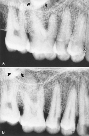
FIG. 4-13 The position of the maxillary zygomatic process in relation to the roots of the molars can help in identifying the orientation of projections. In A, the inferior border of the process lies over the palatal root of the first molar, whereas in B it lies posterior to the palatal root of the first molar. This indicates that when A was made the beam was oriented more from the posterior than when B was made. The same conclusion can be reached independently by examining the roots of the first molar. In A, the palatal root lies behind the distobuccal root, but in B it lies between the two buccal roots.
Peripheral Eggshell Effect
Projection images, those that project a three-dimensional volume onto a two-dimensional receptor, may produce a peripheral eggshell effect. Figure 4-14, A, shows a schematic view of an egg being exposed to an x-ray beam. The top photon has a tangential path through the apex of the egg and a much longer path through the shell of the egg than does the lower photon, which strikes the egg at right angles to the surface and travels through two thicknesses of the shell. As a result, photons traveling through the periphery of a curved surface are more attenuated than those traveling at right angles to the surface. Figure 4-14, B, shows an expansile lesion on the buccal surface of the mandible on an occlusal view. Note how the periphery of the expanded cortex is more opaque than the region inside the expanded border. The cortical bone in not thicker on the cortex than over the rest of the lesion, but rather the x-ray beam is more attenuated in this region because of the longer path length of photons through the bony cortex on the periphery. This peripheral eggshell effect accounts for why the lamina dura, the border of the maxillary sinuses and nasal fossa, and numerous other structures are well demonstrated on projection images. Note that soft tissue masses, such as the nose and tongue, do not show a peripheral eggshell effect because they are uniform rather then being composed of a dense layer surrounding a more lucent interior.
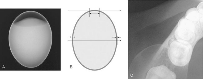
FIG. 4-14 Peripheral eggshell effect. A is a radiograph of a hard-boiled egg. Note how the peripheral rim, the eggshell, is opaque even though the eggshell is uniform in thickness. B shows a schematic view of this egg being exposed to an x-ray beam. The top photon has a tangential path through the apex of the egg and a longer path through the shell of the egg than the lower photon. As a result, photons traveling through the periphery of a curved surface are more attenuated than those traveling at right angles to the surface. C shows an expansile lesion on the buccal surface of the mandible on an occlusal view. Note how the periphery of the expanded cortex is more opaque than the region inside the expanded border as a result of the peripheral eggshell effect.
Chenail, B, Aurelio, JA, Gerstein, H. A model for teaching the Buccal Object Moves Most Rule. J Endod. 1983;9:452–453.
Clark, CA. A method of ascertaining the relative position of unerupted teeth by means of film radiographs. Proc R Soc Med Odontol Sect. 1910;3:87–90.
Goerig, AC, Neaverth, EJ. A simplified look at the buccal object rule in endodontics. J Endod. 1987;13:570–572.
Jacobs, SG. Radiographic localization of unerupted maxillary anterior teeth using the vertical tube shift technique: the history and application of the method with some case reports. Am J Orthod Dentofac Orthop. 1999;116:415–423.
Jacobs, SG. Radiographic localization of unerupted teeth: further findings about the vertical tube shift method and other localization techniques. Am J Orthod Dentofac Orthop. 2000;118:439–447.
Khabbaz, MG, Serefoglou, MH. The application of the buccal object rule for the determination of calcified root canals. Int Endod J. 1996;29:284–287.
Ludlow, JB. The Buccal Object Rule. Dentomaxillofac Radiol. 1999;28:258.
Reader, A. A teaching model for the buccal object rule. J Dent Educ. 1984;48:469–472.
Forsberg, J. A comparison of the paralleling and bisecting-angle radiographic techniques in endodontics. Int Endod J. 1987;20:177–182.
Forsberg, J, Halse, A. Radiographic simulation of a periapical lesion comparing the paralleling and the bisecting-angle techniques. Int Endod J. 1994;27:133–138.
Schulze, RK, d’Hoedt, B. A method to calculate angular disparities between object and receptor in “paralleling technique,”. Dentomaxillofac Radiol. 2002;31:32–38.