Intraoral Radiographic Examinations
Intraoral radiographic examinations are the backbone of imaging for the general dentist. Intraoral radiographs can be divided into three categories: periapical projections, bitewing projections, and occlusal projections. Periapical radiographs should show all of a tooth, including the surrounding bone. Bitewing radiographs show only the crowns of teeth and the adjacent alveolar crests. Occlusal radiographs show an area of teeth and bone larger than periapical radiographs.
A full-mouth set of radiographs consists of periapical and bitewing projections (Fig. 9-1). These projections, when well exposed and properly processed, can provide considerable diagnostic information to complement the clinical examination. As with any clinical procedure, the operator must clearly understand the goals of dental radiography and the criteria for evaluating the quality of performance.
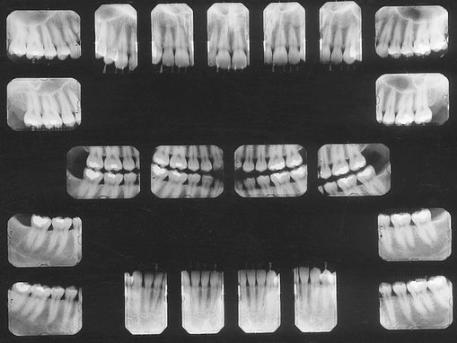
FIG. 9-1 Mounted full-mouth set of radiographs consisting of 17 periapical views and four bitewing views.
Radiographs should be made only when a clear diagnostic need exists for the information the radiograph may provide. Accordingly, the frequency of such examinations varies with the individual circumstances of each patient (see Chapter 15).
Criteria of Quality
Every radiographic examination should produce radiographs of optimal diagnostic quality, incorporating the following features:
• Radiographs should record the complete areas of interest on the image. In the case of intraoral periapical radiographs, the full length of the roots and at least 2 mm of periapical bone must be visible. If evidence of a pathologic condition is present, the area of the entire lesion plus some surrounding normal bone should show on one radiograph. If this is not possible to achieve on a periapical radiograph, an occlusal projection may be required as well as an extraoral projection. Bitewing examinations should demonstrate each posterior proximal surface at least once.
• Radiographs should have the least possible amount of distortion. Most distortion is caused by improper angulation of the x-ray beam rather than by the curvature of the structures being examined or inappropriate positioning of the receptor. Close attention to proper positioning of the receptor and x-ray tube results in diagnostically useful images.
• Radiographs should have optimal density and contrast to facilitate interpretation. Although milliamperage (mA), peak kilovoltage (kVp), and exposure time are crucial parameters influencing density and contrast, faulty processing can adversely affect the quality of a properly exposed radiograph.
When evaluating radiographs and considering whether to retake a view, the practitioner should consider the initial reason for making the image. When a full-mouth set is indicated, it is not necessary to retake a view that fails to open a contact or show a periapical region if the missing information is available on another view. If a single view or only a few views are needed, they should be repeated only if they fail to reveal the desired information.
Periapical Radiography
Two intraoral projection techniques are commonly used for periapical radiography: the paralleling technique and the bisecting-angle technique. Most clinicians prefer the paralleling technique because it provides a less distorted view of the dentition. The paralleling technique is the most appropriate technique for digital imaging. The following discussion describes the principles and uses of the paralleling technique to obtain a full-mouth set of radiographs. When anatomic configuration (e.g., palate and floor of the mouth) precludes strict adherence to the paralleling concept, slight modifications may have to be made. If the anatomic constraints are extreme, some of the principles of the bisecting-angle technique may be used to accomplish the required receptor placement and determine the vertical angulation of the tube. The bisecting-angle technique is described later in the chapter.
The term image receptor refers to any medium that can capture an image including film, charge-coupled device (CCD) or complementary metal oxide semiconductors (CMOS) sensors, or storage phosphor plates. The principles for making radiographs are the same for each of these receptor types; thus this chapter uses the general term receptor to refer any of the image receptors.
GENERAL STEPS FOR MAKING AN EXPOSURE
• Prepare unit for exposure. Place barriers for universal infection control and have receptors and receptor-holding instruments ready at chairside (see Chapter 9).
• Greet and seat the patient. Position the patient upright in the chair with the back and head well supported and briefly describe the procedures that are to be performed. Position the dental chair low for maxillary projections and elevated for mandibular projections. Ask the patient to remove eyeglasses and all removable appliances. Drape the patient with a lead apron regardless of whether a single image or a full series is to be made. Do not comment on any discomfort the patient may feel during the procedure. If it seems necessary to apologize for any discomfort, do it after the examination.
• Adjust the x-ray unit setting. Set the x-ray machine for the proper kVp, mA, and exposure time. Generally only the exposure time is adjusted for the various anatomic locations.
• Wash hands thoroughly. Wash your hands with soap and water, preferably in front of the patient or at least in an area where the patient can observe or be aware of the washing. Put on disposable gloves.
• Examine the oral cavity. Before placing any receptors in the mouth, examine the teeth to estimate their axial inclination, which influences the placement of the receptor. Also note tori or other obstructions that modify receptor placement.
• Position the tube head. Bring the tube head to the side to be examined so that it is readily available for final positioning after the receptor has been placed in the mouth.
• Position the receptor. Insert receptor into the holding device and position the receptor and holding device in the region of the patient’s mouth to be examined. Leading with the apical end of the receptor, rotate it into the oral cavity. Place the receptor as far from the teeth as possible. This provides the maximal space available in the midline of the palate and the greatest depth toward the center of the floor of the mouth. The added space allows the receptor to be oriented parallel to the long axis of the teeth. With the receptor now in the mouth, place it gently on the palate or floor of the mouth. Next, rotate the receptor-holding instrument either up or down until the bite-block rests on the teeth to be radiographed. Place a cotton roll between the bite-block and the teeth opposite those being radiographed. This helps stabilize the receptor-holding instrument and in many cases contributes to the patient’s comfort. Then ask the patient to close his or her mouth gently, holding the instrument and receptor in place. If the bite-block is not on the teeth when the patient closes, the receptor may move into the palate or floor of the mouth and may cause discomfort from faulty positioning.
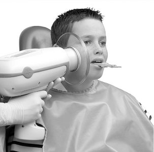
• Position the x-ray tube. Adjust the vertical and horizontal angulation of the tube head to correspond to the receptor-holding instrument. The end of the aiming cylinder of the x-ray machine must be flush or parallel to the guide ring instrument. Alignment is satisfactory when the aiming cylinder covers the port and is within the limits of the face shield. Caution the patient not to move.
• Make the exposure. Make the exposure with the preset exposure time. If the receptor is a film or storage phosphor plate, then after exposure remove the receptor from the patient’s mouth, dry it with a paper towel, and place it in an appropriate receptacle outside the exposure area. If the receptor is a CCD or CMOS sensor, then you may be able to keep it in the patient’s mouth and reposition it for the next view. Encourage the patient along the way.
A typical full-mouth set of radiographs consists of 21 images (Box 9-1, see also Fig. 9-1). Establish a regular sequence when making exposures to avoid overlooking individual projections. Make the anterior views before the posterior views because the former causes less discomfort for the patient. The following description of procedures pertains to the paralleling technique.
PARALLELING TECHNIQUE
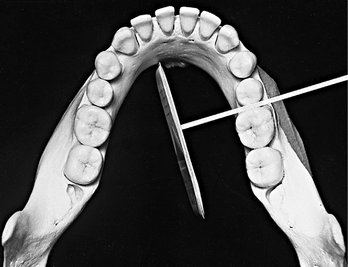
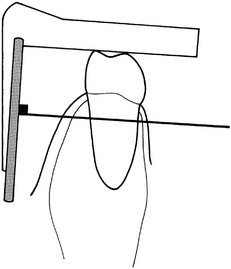
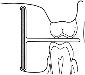
The central concept of the paralleling technique (also called the right-angle or long-cone technique) is that the x-ray receptor is supported parallel to the long axis of the teeth and the central ray of the x-ray beam is directed at right angles to the teeth and receptor (Fig. 9-2). This orientation of the receptor, teeth, and central ray minimizes geometric distortion and presents the teeth and supporting bone in their true anatomic relationships. To reduce geometric distortion, the x-ray source should be located relatively distant from the teeth. The use of a long source-to-object distance reduces the apparent size of the focal spot, thus increasing image sharpness, and provides images with minimal magnification. The paralleling method works equally well for film, CCD or CMOS sensors, or storage phosphor plates.
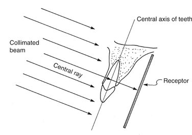
FIG. 9-2 Paralleling technique illustrates the parallelism between the long axis of the tooth and the receptor. The central ray is directed perpendicular to each.
Receptor-Holding Instruments
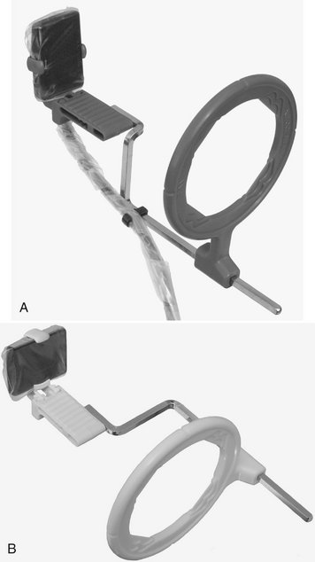
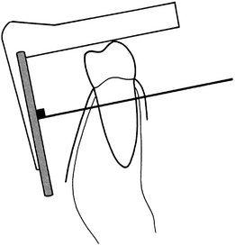
Use instruments to allow precise positions of the receptor in the patient’s mouth. Many of these receptor holders are specific for various brands of digital sensors, storage phosphor plates, or film. It is also important to use a receptor-holding instrument that has an external guiding ring. This guiding ring is used to align the x-ray aiming cylinder and ensures that the receptor is centered in the beam behind the teeth of interest and that the receptor and teeth are perpendicular to the x-ray beam (Fig. 9-3). These should be used with rectangular collimators to reduce patient exposure (Chapter 3).
Receptor Placement
For the best images, the receptor should be positioned parallel to the teeth and deep in the patient’s mouth. This is particularly important when rigid sensors are used because they may be larger than film. For maxillary projections, the superior border of the receptor generally rests at the height of the palatal vault in the midline. Similarly, for mandibular projections, the receptor should be used to displace the tongue posteriorly or toward the midline to allow the inferior border of the receptor to rest on the floor of the mouth away from the mucosa on the lingual surface of the mandible. Especially for digital sensors, patient acceptance and comfort are best when the receptor is placed in the center of the mouth.
Angulation of the Tube Head
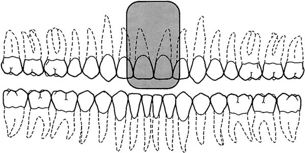
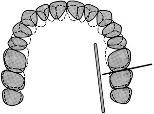
The orientation of the x-ray machine’s aiming cylinder in the vertical and horizontal planes should be adjusted to align with the aiming ring. The horizontal direction of the beam primarily influences the degree of overlapping of the images of the crowns at the interproximal spaces (Fig. 9-4).
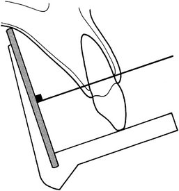
BISECTING-ANGLE TECHNIQUE
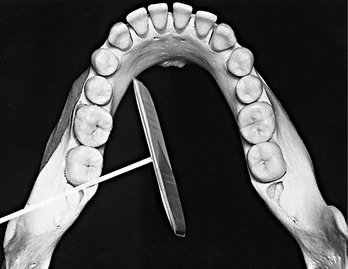
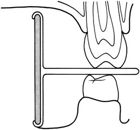
The bisecting-angle technique was used often in the first half of the 1900s but has been largely replaced by the paralleling technique. This method may be useful when the operator is unable to apply the paralleling technique because of large rigid sensors or the anatomy of the patient. The bisecting-angle technique is based on a simple geometric theorem, Cieszynski’s rule of isometry, which states that two triangles are equal when they share one complete side and have two equal angles. Dental radiography applies the theorem as follows. The receptor is positioned as close as possible to the lingual surface of the teeth, resting in the palate or in the floor of the mouth (Fig. 9-5). The plane of the receptor and the long axis of the teeth form an angle with its apex at the point where the receptor is in contact with the teeth along an imaginary line that bisects this angle and directs the central ray of the beam at right angles to this bisector. This forms two triangles with two equal angles and a common side (the imaginary bisector). Consequently, when these conditions are satisfied, the images cast on the receptor theoretically are the same length as the projected object. To reproduce the length of each root of a multirooted tooth accurately, the central beam must be angled differently for each root. Another limitation of this technique is that the alveolar ridge often projects more coronally than its true position, thus distorting the apparent height of the alveolar bone around the teeth.
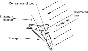
FIG. 9-5 Bisecting-angle technique shows the central ray directed at a right angle to the plane that bisects the angle between the long axis of the tooth and the receptor.
Receptor-Holding Instruments
Several methods can be used to support receptors intraorally for bisecting-angle projections. The preferred method is to use a receptor-holding bisecting-angle instrument that provides an external device for localizing the x-ray beam. The bisecting-angle instrument uses a fixed average bisecting angle. It is not desirable to have the patient support the receptor from the lingual surface with his or her forefinger. Patients often use excessive force and bend the receptor, causing distortion of the image. Also, the receptor might slip without the operator’s expertise, resulting in an improper image field. Finally, without an external guide to the position of the receptor, the x-ray beam may miss part of the receptor, resulting in a partial image (cone cut).
Positioning of the Patient
For radiographs of the maxillary arch, the patient’s head should be positioned upright with the sagittal plane vertical and the occlusal plane horizontal. When the mandibular teeth are to be radiographed, the head is tilted back slightly to compensate for the changed occlusal plane when the mouth is opened.
Receptor Placement
The projections described for the paralleling technique may also be used for the bisecting-angle technique. The receptor is positioned behind the area of interest, with the apical end against the mucosa on the lingual or palatal surface. The occlusal or incisal edge is oriented against the teeth with an edge of the receptor extending just beyond the teeth. If necessary for the patient’s comfort, the anterior corner of a film can be softened by bending it before it is placed against the mucosa. Care must be taken not to bend the film excessively because this may result in considerable image distortion and pressure defects in the emulsion that are apparent on the processed receptor. Such bending is not possible with CCD or CMOS sensors or storage phosphor plates.
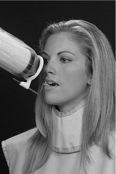
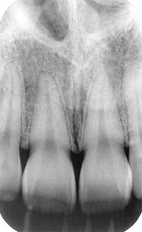
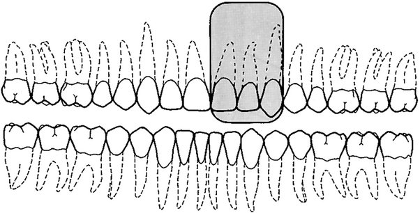
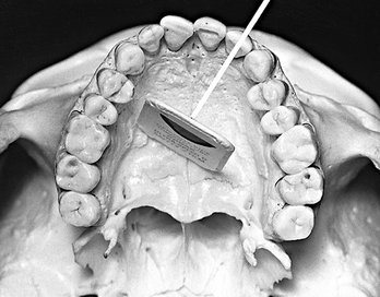
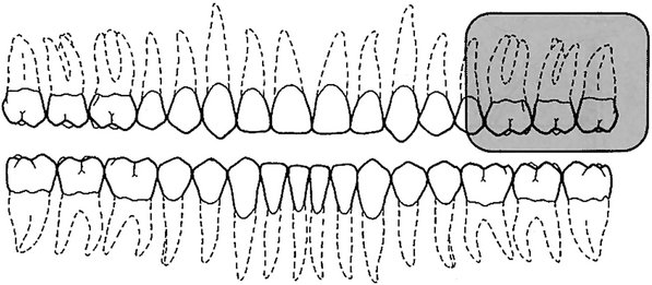
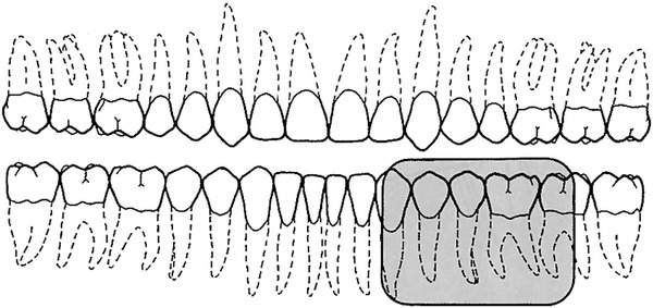
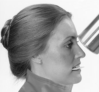
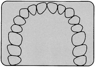
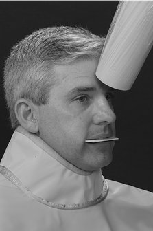
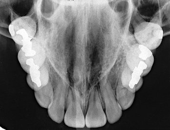
PARALLELING TECHNIQUE • MAXILLARY CENTRAL INCISOR PROJECTION*
The field of view on these radiographs (shaded area) should include both central incisors and their periapical areas.
Place a No. 1 receptor at about the level of the second premolars or first molars to take advantage of the maximal palatal height so that the entire length of the teeth can be projected on it. Have the receptor resting on the palate with its midline centered with the midline of the arch. Position the packet’s long axis parallel to the long axis of the maxillary central incisors.
Projection of Central Ray.†
Direct the central ray through the contact point of the central incisors and perpendicular to the plane of the receptors and roots of the teeth. Because the axial inclination of the maxillary incisors is about 15 to 20 degrees, the vertical angulation of the tube should be at the same positive angle. The tube should have 0 horizontal angulation.
Direct the point of entry of the central ray high on the lip, in the midline, just below the septum of the nostril. If the palatal vault is unusually low or a palatal torus is present, it may be necessary to tilt the receptor holder positively and compromise a completely parallel relationship between the receptor and the teeth to ensure that the periapical region is included on the image.
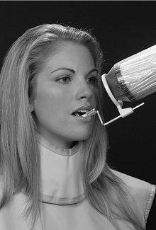
*Patient photos for the paralleling technique on pages 114, 116, 118, 120, 122, 124, 126, 128, 130, 132, and 134 are from Iannucci J, Jansen Howerton L: Dental radiography: principles and techniques, ed 3, St. Louis, 2006, Saunders.
†Projection of the central ray and point of entry are described in the discussion of the paralleling technique for instances when a receptor-holding device without a tube alignment ring or face shield is used. When using a receptor-holding device with a tube-alignment ring or face shield, position the device in the mouth to give the appropriate horizontal and vertical angulation.
PARALLELING TECHNIQUE • MAXILLARY LATERAL PROJECTION
This projection should show the lateral incisor and its periapical field centered on the radiograph. Include the mesial interproximal area with the distal aspect of the central incisor on the radiograph so that no overlap is evident.
Place a No. 1 receptor deep in the oral cavity parallel with the long axis and the mesiodistal plane of the maxillary lateral incisor.
PARALLELING TECHNIQUE • MAXILLARY CANINE PROJECTION
This projection should demonstrate the entire canine, with its periapical area, in the midline of the radiograph. Open the mesial contact area. Ignore the distal contact because it will be visualized on other projections.
Place a No. 1 receptor against the palate, well away from the palatal surface of the teeth. Orient the receptor packet with its anterior edge at about the middle of the lateral incisor and its long axis parallel with the long axis of the canine.

PARALLELING TECHNIQUE • MAXILLARY PREMOLAR PROJECTION
The radiograph of this region should include the images of the distal half of the canine and the premolars, with room for at least the first molar.
Place a No. 2 receptor in the mouth with the long dimension parallel with the occlusal plane and in the midline and near the palatal midline. The packet should extend far enough forward to cover the distal half of the canine. It will also include the premolars and the first molar and maybe the mesial portion of the second molar. The plane of the receptor should be nearly vertical to correspond with the long axis of the premolar teeth. Position the receptor-holding device so that the long axis of the receptor is parallel with the mean buccal plane of the premolars. This establishes the proper horizontal angulation.
PARALLELING TECHNIQUE • MAXILLARY MOLAR PROJECTION
The radiograph of this region should show the images of the distal half of the second premolar, the three maxillary permanent molars, and some of the tuberosity. Include the same area on the receptor even if some or all molars are missing. If the third molar is impacted in an area other than the region of the tuberosity, a distal oblique or extraoral projection (e.g., panoramic or oblique lateral jaw view) may be required.
When placing the No. 2 receptor for this projection, position the wide dimension of the receptor nearly horizontal to minimize brushing the palate and dorsum of the tongue. When the receptor is in the region to be examined, rotate it into position with a firm and definite motion. This maneuver is important in avoiding the gag reflex, and resolute action by the operator enhances the patient’s confidence. Place the receptor far enough posterior to cover the first, second, and third molar areas and some of the tuberosity. The anterior border should just cover the distal aspect of the second premolar. To cover the molars from crown to apices, place the receptor at the midline of the palate. In this position room should be available to orient the receptor parallel with the molar teeth. The mesial or distal rotation of the receptor-holding device should ensure that the long axis of the receptor is parallel with the mean buccal plane of the molars (to establish the proper horizontal angulation). A shallow palate may require slight tipping of the holding instrument to avoid bending the receptor.
NOTE: In some cases the size of the mouth (length of the arch) does not allow positioning of the receptor (holding device) as far posterior as recommended for the molar projection. However, by placing the receptor-holding device so that half the tube alignment ring or face shield is behind the outer canthus of the eye, the molars and part of the tuberosity usually can be included in the image of the molar projection.
PARALLELING TECHNIQUE • MAXILLARY DISTAL OBLIQUE MOLAR PROJECTION
This projection provides a view of the maxillary tuberosity region more posterior than usually is seen in the molar projection. It allows detection or evaluation of impacted teeth or pathologic conditions in the bone of this area.
Position the holding device with a No. 2 receptor in the molar region of the maxilla and rotate distally, angling the receptor across the midline so that the posterior border is away from the teeth of interest and the anterior border is near the molars on the side being radiographed. Position this receptor with a definite movement to minimize patient discomfort.
Direct the central ray from the posterior aspect through the third molar region and perpendicular to the angled receptor, projecting the more posterior objects anteriorly onto the receptor.
The central ray enters the maxillary third molar region just below the middle of the zygomatic arch, distal to the lateral canthus of the eye.

NOTE: Occasionally a hypersensitive patient gags when a receptor is placed for the usual maxillary molar projection. However, if a modified distal oblique projection is used, moving the posterior border of the receptor more medially frequently is less irritating to the patient, and the image is obtained with comfort. The patient’s reaction of relief indicates when a sufficient rotation has been achieved. Although this maneuver may result in some overlapping of the molar contact areas, these surfaces will be apparent on the bitewing projection. Slight overlapping of contact areas is preferable to no radiograph of the region.
PARALLELING TECHNIQUE • MANDIBULAR CENTROLATERAL PROJECTION
Center the image of the mandibular central and lateral incisors and their periapical areas on the receptor. Because the space in this area frequently is restricted, use two of the narrower anterior periapical receptors for the incisors to provide good coverage with minimal discomfort. In addition, the incisor contact areas are better visualized on two narrower anterior receptors because the angulation of the central ray can be adjusted for the contact area on each side.
Place the long dimension of the No. 1 receptor vertically behind the central and lateral incisors with the contact area centered and the lower border below the tongue. Position the receptor posteriorly as far as possible, usually between the premolars. With the receptor resting gently on the floor of the mouth as the fulcrum, tip the instrument downward until the receptor-holder bite-block is resting on the incisors. Instruct the patient to close the mouth slowly. As the patient is closing slowly and the floor of the mouth is relaxing, rotate the instrument with the teeth as the fulcrum to align the receptor to be more parallel with the teeth.

PARALLELING TECHNIQUE • MANDIBULAR CANINE PROJECTION
This image should show the entire mandibular canine and its periapical area. Open its mesial contact area. The distal contact is included on other projections.
Place a No. 1 receptor packet in the mouth with its long dimension vertical and the canine in the midline of the receptor. Position it as far lingual as the tongue and contralateral alveolar process permit, with its long axis parallel and in line with the canine. The instrument must be tipped with the bite-block on the canine before the patient is asked to close.

PARALLELING TECHNIQUE • MANDIBULAR PREMOLAR PROJECTION
The radiograph of this area should show the distal half of the canine, the two premolars, and the first molar.
Bring the No. 2 receptor into the mouth with its plane nearly horizontal. Rotate the lead edge to the floor of the mouth between the tongue and the teeth with the anterior border near the midline of the canine. Place the receptor away from the teeth to position it in the deeper portion of the mouth. Placing the receptor toward the midline also provides more room for the anterior border of the receptor in the curvature of the jaw as it sweeps anteriorly. Prevent the anterior border from contacting the very sensitive attached gingiva on the lingual surface of the mandible.
Position the receptor-holding instrument to project the central ray through the second premolar-molar area. The vertical angulation should be small, nearly parallel with the occlusal plane, to keep the receptor as nearly parallel with the long axis of the teeth as possible. Adjust the horizontal angulation and the placement of the receptor-holding device to direct the beam through the premolar contact points.
PARALLELING TECHNIQUE • MANDIBULAR MOLAR PROJECTION
The radiograph of this region should include the distal half of the second premolar and the three mandibular permanent molars. In the case of an impacted third molar or a pathologic condition distal to the third molar, a distal oblique molar projection or even additional extraoral projections (panoramic or lateral ramus) may be required to demonstrate the area adequately. If the molar area is edentulous, place the receptor far enough posterior to include the retromolar area in the examination.
Place the No. 2 receptor in the mouth with its plane nearly horizontal. Rotate the inferior edge downward beneath the lateral border of the tongue, displacing it medially. The anterior edge of the receptor should be at about the middle of the second premolar. In most cases the tongue forces the receptor near the alveolar process and molars, aligning it parallel with the long axis of the teeth and the line of occlusion.
Proper placement of the holding instrument directs the central ray through the second molar. Adjust the horizontal angulation to project the beam through the contact areas. Because of the slight lingual inclination of the molars, the central ray may have some slight positive angulation (approximately 8 degrees).
PARALLELING TECHNIQUE • MANDIBULAR DISTAL OBLIQUE MOLAR PROJECTION
The distal oblique projection provides a view of the third molar and the retromolar area of the mandible that usually is not included in the molar radiograph. It is intended primarily for detection or examination of impacted teeth and pathologic conditions in the bone in this area rather than for the teeth themselves; the images of the teeth are distorted and overlap because of the oblique path of the x-ray beam. This projection may eliminate the requirement for an extraoral radiograph of the area.
Place the receptor holder in the floor of the mouth between the tongue and alveolar process and parallel with the long axis of the molars. Position the instrument as far posteriorly as possible and then rotate the receptor-holding device distally, moving the posterior margin of the receptor toward the midline. The beam is directed posteroanteriorly, and more distal objects are projected anteriorly onto the receptor.

Angulation of the Tube Head
Horizontal Angulation.: When a receptor-holding device with a beam-localizing ring is used, the instrument is positioned horizontally so that when the tube is aligned with the ring, the central ray is directed through the contacts in the region being examined. If the receptor-holding device does not have a beam-localizing feature, the tube is pointed so as to direct the central ray through the contacts. In this situation the radiation beam is also centered on the receptor. This angulation usually is at right angles (in the horizontal projection) to the buccal or facial surfaces of the teeth in each region.
Vertical Angulation.: In practice, the clinician’s goal is to aim the central ray of the x-ray beam at right angles to a plane bisecting the angle between the receptor and the long axis of the tooth. This principle works well with flat, two-dimensional structures, but teeth that have depth or are multirooted show evidence of distortion. Excessive vertical angulation results in foreshortening of the image, whereas insufficient vertical angulation results in image elongation. The angle that directs the central ray perpendicular to the bisecting plane varies with the individual’s anatomy. Several measurements can be used as a general guide when the occlusal plane is oriented parallel with the floor (Table 9-1).
TABLE 9-1
Angulation Guidelines for Bisecting-Angle Projections*
| PROJECTION | MAXILLA | MANDIBLE |
| Incisors | +40 degrees | −15 degrees |
| Canines | +45 degrees | −20 degrees |
| Premolars | +30 degrees | −10 degrees |
| Molars | +20 degrees | −5 degrees |
NOTE: With a positive (+) angulation the aiming tube is pointed downward, and with a negative (−) angulation it is pointed upward.
*When the occlusal plane is oriented parallel with the floor.
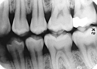
BITEWING EXAMINATIONS
Bitewing (also called interproximal) radiographs include the crowns of the maxillary and mandibular teeth and the alveolar crest on the same receptor. Bitewing receptors are particularly valuable for detecting interproximal caries in the early stages of development before it becomes clinically apparent. Because of the horizontal angle of the x-ray beam, these radiographs also may reveal secondary caries below restorations that may escape recognition in the periapical views. Bitewing projections are also useful for evaluating the periodontal condition. They provide a good perspective of the alveolar bone crest, and changes in bone height can be assessed accurately through comparison with the adjacent teeth. In addition, because of the angle of projection directly through the interproximal spaces, the bitewing receptor is especially effective and useful for detecting calculus deposits in interproximal areas. (Because of its relatively low radiodensity, calculus is better visualized on radiographs made with reduced exposure.) The long axis of bitewing receptors usually is oriented horizontally but may be oriented vertically.
Horizontal Bitewing Receptors
To obtain the desirable characteristics of the bitewing examination described, the beam is carefully aligned between the teeth and parallel with the occlusal plane. As the receptor or receptor-holding instrument is placed in the mouth, the portion of the mandibular quadrant that is being radiographed is in view. The position of the teeth in this segment of the mandibular quadrant is evaluated, and the beam is directed through the contacts. Some difference may exist in the curvature of the mandibular and maxillary arches. However, when the x-ray beam is accurately directed through the mandibular premolar contacts, overlapping is minimal or absent in the maxillary premolar segment. A few degrees of tolerance are available in the horizontal angulation before overlapping becomes critical. The contact between the maxillary first and second molars often is angled a few degrees more anteriorly than between the mandibular first and second molars. The aiming cylinder is positioned about +10 degrees to project the beam parallel with the occlusal plane (occlusal dentinoenamel junction [DEJ]). This minimizes overlapping of the opposing cusps onto the occlusal surface and thus improves the probability of detecting early occlusal lesions at the DEJ.
The XCP bitewing instrument has an external guide ring for positioning the tube head. This reduces the possibility of cone cutting the receptor (Fig. 9-6). To position the XCP instrument properly, the guide bar is placed parallel with the direction of the beam that opens the contacts of the dentition being examined.
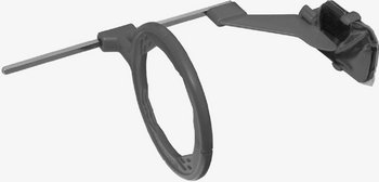
FIG. 9-6 Receptor-holding device for bitewing radiographs. Note the external localizing ring, which is used to position the aiming tube of the x-ray machine to ensure that the entire receptor is in the x-ray beam. (Courtesy Dentsply Rinn, Elgin, Ill.)
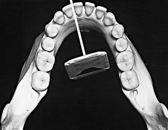
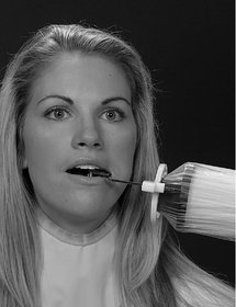
A receptor fitted with a bitewing tab or loop may be used instead of a holding device (Fig. 9-7). The receptor is placed in a comfortable position lingual to the teeth to be examined. The aiming cylinder is oriented in the predetermined direction that passes the x-ray beam through the interproximal spaces. To help prevent cone cutting, the central ray is directed toward the center of the bitewing tab, which protrudes to the buccal side. The beam is angulated +7 to +10 degrees vertically to preclude overlap of the cusps onto the occlusal surface.
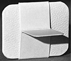
FIG. 9-7 Bitewing loop, showing the tab that the patient bites on to support the receptor (film) during exposure.
Two posterior bitewing views, a premolar and a molar, are recommended for each quadrant. However, for children aged 12 years or younger, one bitewing receptor (No. 2 receptor) usually suffices. The premolar projection should include the distal half of the canines and the crowns of the premolars. Because the mandibular canines usually are more mesial than the maxillary canines, the mandibular canine is used as the guide for placement of the premolar bitewing receptor. The molar bitewing receptor is placed 1 or 2 mm beyond the most distally erupted molar (maxillary or mandibular).
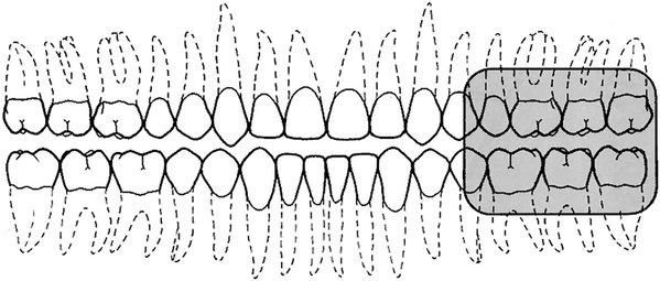
Vertical Bitewing Receptors
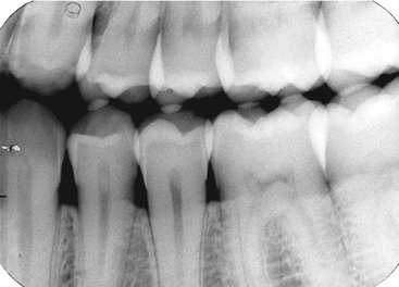
Vertical bitewing receptors usually are used when the patient has moderate to extensive alveolar bone loss. Orienting the length of the receptor vertically increases the likelihood that the residual alveolar crests in the maxilla and the mandible will be recorded on the radiograph (Fig. 9-8). The principles for positioning the receptor and orienting the x-ray beam are otherwise the same as for horizontal bitewing projections.
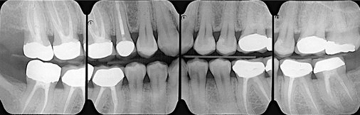
FIG. 9-8 A set of vertical bitewings. Orienting the length of the receptor vertically increases the likelihood that, even in patients with extensive alveolar bone loss, the residual alveolar crests in the maxilla and the mandible will be recorded on the radiograph.
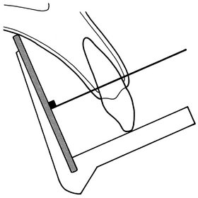
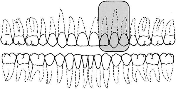
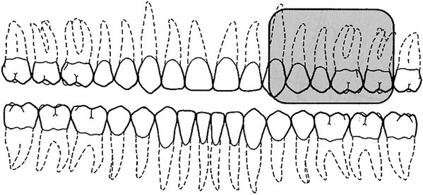
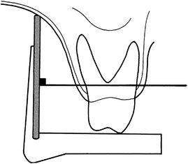
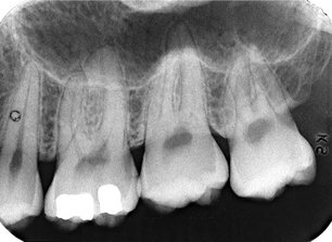
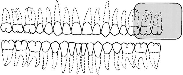
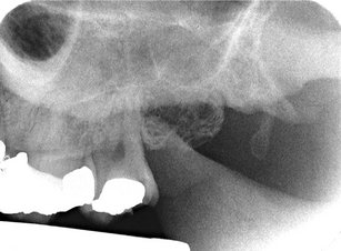
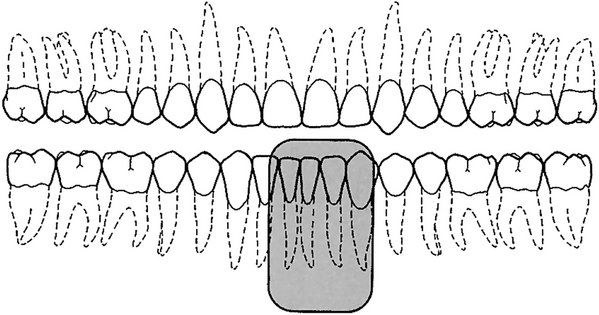
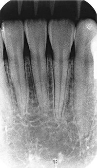
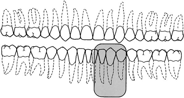
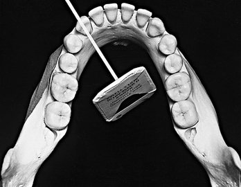
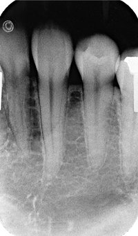
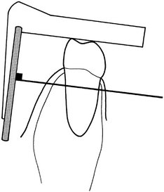
PREMOLAR BITEWING PROJECTION*
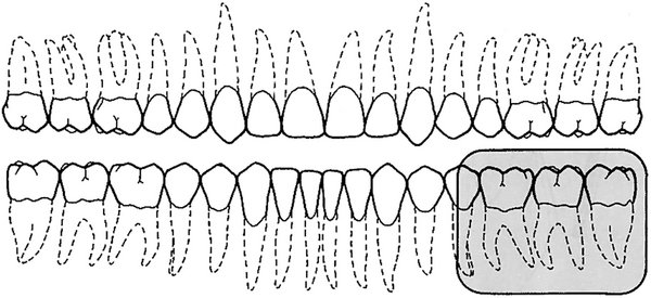
This projection should cover the distal portion of the mandibular canine anteriorly and show equally the crowns of the maxillary and mandibular premolar teeth.
Place the receptor between the tongue and the teeth, far enough from the lingual surface of the teeth to prevent interference by the palate on closing and parallel to the long axes of the teeth. The anterior border of the receptor should extend beyond the contact area between the mandibular canine and the first premolar. Hold the receptor in place until the patient’s mouth is completely closed. Holding the receptor while closing prevents it from being displaced distally.
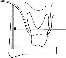
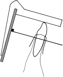
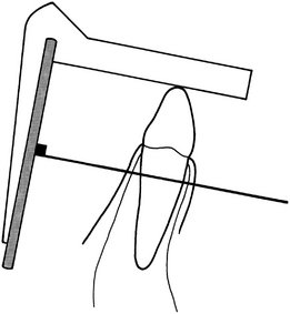
Adjust the horizontal angulation of the cone to project the central ray to the center of the receptor through the premolar contact areas. To compensate for the slight inclination of the receptor against the palatal mucosa, the vertical angulation should be about +5 degrees. (In the drawing, the mandibular teeth are in dashed lines.)
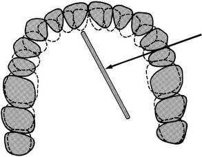
Identify the point of entry by retracting the cheek and determining that the central ray will enter the line of occlusion at the point of contact between the second premolar and the first molar.
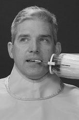
*Patient photos for the bitewing projections on pages 138 and 140 are from Iannucci J, Jansen Howerton L: Dental radiography: principles and techniques, ed 3, St. Louis, 2006, Saunders.
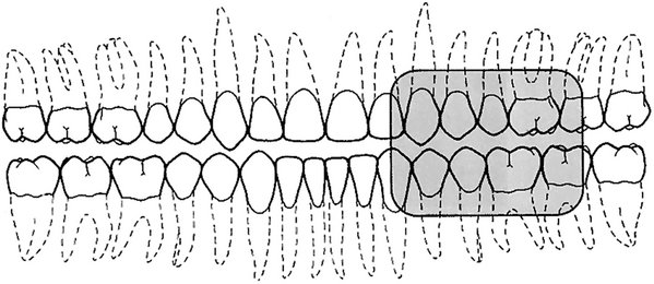
MOLAR BITEWING PROJECTION
This projection should show the distal surface of the most posterior erupted molar and equally the crowns of the maxillary and mandibular molars. Because the maxillary and mandibular molar contact areas may not be open from the same horizontal angulation, they may not be visible on one receptor. In this case it may be desirable to open the maxillary molar contacts because the mandibular molar contacts usually are open on the periapical receptors.
Place the receptor between the tongue and teeth, as far lingual as practical to avoid contacting the sensitive attached gingiva. The distal margin of the receptor should extend 1 to 2 mm beyond the most posterior erupted molar. When using the XCP, adjust the horizontal angulation by placing the guide bar parallel with the direction of the central ray to open the contact area between the first and second molars.
Project the central ray to the center of the receptor and through the contact of the first and second maxillary molars. Angle the central ray slightly from the anterior because the molar contacts usually are not oriented at right angles to the buccal surfaces of these teeth. A vertical angulation of +10 degrees is recommended. (In the drawing, the mandibular teeth are in dashed lines.)

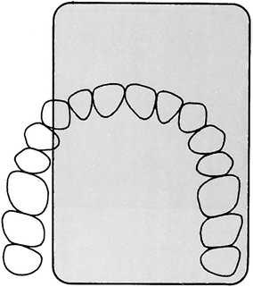
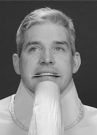
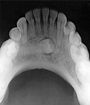
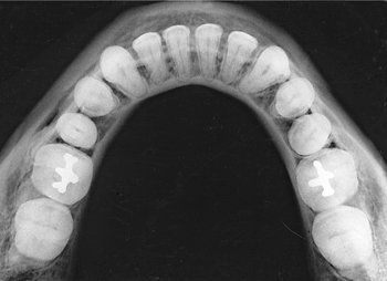
ANTERIOR MAXILLARY OCCLUSAL PROJECTION
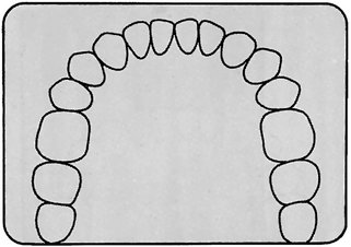
The primary field of this projection includes the anterior maxilla and its dentition and the anterior floor of the nasal fossa and teeth from canine to canine.
Adjust the patient’s head so that the sagittal plane is perpendicular and the occlusal plane is horizontal to the floor. Place the receptor in the mouth with the exposure side toward the maxilla, the posterior border touching the rami, and the long dimension of the receptor perpendicular to the sagittal plane. The patient stabilizes the receptor by gently closing the mouth or using gentle bilateral thumb pressure.

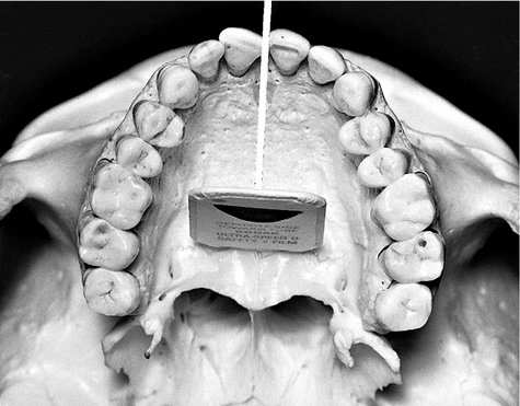
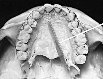
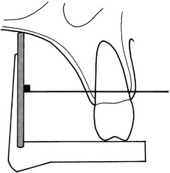
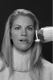
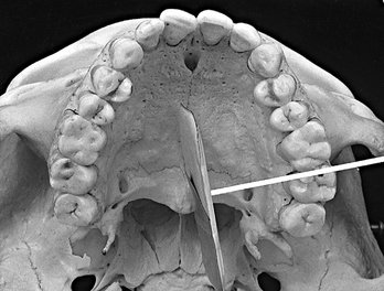
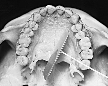
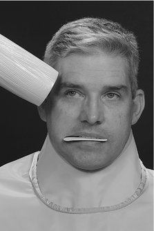
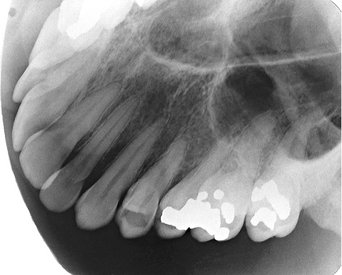
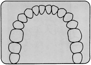
CROSS-SECTIONAL MAXILLARY OCCLUSAL PROJECTION*
This projection shows the palate, zygomatic processes of the maxilla, anteroinferior aspects of each antrum, nasolacrimal canals, teeth from second molar to second molar, and nasal septum.
Seat the patient upright with the sagittal plane perpendicular to the floor and the occlusal plane horizontal. Place the receptor, with its long dimension perpendicular to the sagittal plane, crosswise in the mouth. Gently push the receptor in backward until it contacts the anterior border of the mandibular rami. The patient stabilizes the receptor by gently closing the mouth.
Direct the central ray at a vertical angulation of +65 degrees and a horizontal angulation of 0 degrees, to the bridge of the nose just below the nasion, toward the middle of the receptor.
*Patient photo for this occlusal projection is from Iannucci J, Jansen Howerton L: Dental radiography: principles and techniques, ed 3, St. Louis, 2006, Saunders.
LATERAL MAXILLARY OCCLUSAL PROJECTION*
This projection shows a quadrant of the alveolar ridge of the maxilla, inferolateral aspect of the antrum, tuberosity, and teeth from the lateral incisor to the contralateral third molar. In addition, the zygomatic process of the maxilla superimposes over the roots of the molar teeth.
Place the receptor with its long axis parallel to the sagittal plane and on the side of interest, with the tube side toward the side of the maxilla in question. Push the receptor posteriorly until it touches the ramus. Position the lateral border parallel with the buccal surfaces of the posterior teeth, extending laterally approximately 1 cm past the buccal cusps. Ask the patient to close gently to hold the receptor in position.
Orient the central ray with a vertical angulation of +60 degrees, to a point 2 cm below the lateral canthus of the eye, directed toward the center of the receptor.
*Patient photo for this occlusal projection is from Iannucci J, Jansen Howerton L: Dental radiography: principles and techniques, ed 3, St. Louis, 2006, Saunders.
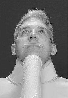
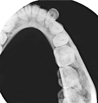
ANTERIOR MANDIBULAR OCCLUSAL PROJECTION*
This projection includes the anterior portion of the mandible, the dentition from canine to canine, and the inferior cortical border of the mandible.
Seat the patient tilted back so that the occlusal plane is 45 degrees above horizontal. Place the receptor in the mouth with the long axis perpendicular to the sagittal plane and push it posteriorly until it touches the rami. Center the receptor with the pebbled side (tube side) down and ask the patient to bite lightly to hold the receptor in position.
Orient the central ray with −10 degrees angulation through the point of the chin toward the middle of the receptor; this gives the ray −55 degrees of angulation to the plane of the receptor.
*Patient photo for this occlusal projection is from Iannucci J, Jansen Howerton L: Dental radiography: principles and techniques, ed 3, St. Louis, 2006, Saunders.
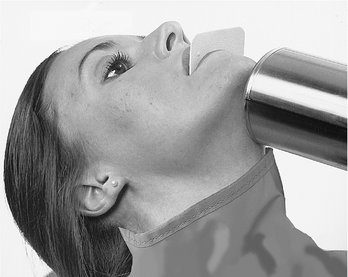
CROSS-SECTIONAL MANDIBULAR OCCLUSAL PROJECTION*
This projection includes the soft tissue of the floor of the mouth and reveals the lingual and buccal plates of the mandible from second molar to second molar. When this view is made to examine the floor of the mouth (e.g., for sialoliths), the exposure time should be reduced to half the time used to create an image of the mandible.
Seat the patient in a semireclining position with the head tilted back so that the ala-tragus line is almost perpendicular to the floor. Place the receptor in the mouth with its long axis perpendicular to the sagittal plane and with the tube side toward the mandible. The anterior border of the receptor should be approximately 1 cm beyond the mandibular central incisors. Ask the patient to bite gently on the receptor to hold it in position.
Direct the central ray at the midline through the floor of the mouth approximately 3 cm below the chin, at right angles to the center of the receptor.
The point of entry of the central ray is in the midline through the floor of the mouth approximately 3 cm below the chin.
*Patient photo for this occlusal projection is from Iannucci J, Jansen Howerton L: Dental radiography: principles and techniques, ed 3, St. Louis, 2006, Saunders.
LATERAL MANDIBULAR OCCLUSAL PROJECTION
This projection covers the soft tissue of half the floor of the mouth, the buccal and lingual cortical plates of half of the mandible, and the teeth from the lateral incisor to the contralateral third molar. When this view is used to provide an image of the floor of the mouth, the exposure time should be reduced to half that used to provide an image of the mandible.

Seat the patient in a semireclining position with the head tilted back so that the ala-tragus line is almost perpendicular to the floor. Place the receptor in the mouth with its long axis initially parallel with the sagittal plane and with the pebbled side down toward the mandible. Place the receptor as far posterior as possible, then shift the long axis buccally (right or left) so that the lateral border of the receptor is parallel with the buccal surfaces of the posterior teeth and extends laterally approximately 1 cm.
Occlusal Radiography
An occlusal radiograph displays a relatively large segment of a dental arch. It may include the palate or floor of the mouth and a reasonable extent of the contiguous lateral structures. Occlusal radiographs also are useful when patients are unable to open wide enough for periapical radiographs or for other reasons cannot accept periapical receptors. Because occlusal radiographs are exposed at a steep angulation, they may be used with conventional periapical radiographs to determine the location of objects in all three dimensions. Typically, the occlusal radiograph is especially useful in the following cases:
• To precisely locate roots and supernumerary, unerupted, and impacted teeth (this technique is especially useful for impacted canines and third molars)
• To localize foreign bodies in the jaws and stones in the ducts of sublingual and submandibular glands
• To demonstrate and evaluate the integrity of the anterior, medial, and lateral outlines of the maxillary sinus
• To aid in the examination of patients with trismus, who can open their mouths only a few millimeters; this condition precludes intraoral radiography, which may be impossible or at least extremely painful for the patient
• To obtain information about the location, nature, extent, and displacement of fractures of the mandible and maxilla
• To determine the medial and lateral extent of disease (e.g., cysts, osteomyelitis, malignancies) and to detect disease in the palate or floor of the mouth
To make an occlusal radiograph, a relatively large receptor (7.7 × 5.8 cm [3 × 2.3 inches]) is inserted between the occlusal surfaces of the teeth. Occlusal receptors are made only of film or storage phosphor plates. Neither CCD nor CMOS sensors exist this large. As its name implies, the receptor lies in the plane of occlusion. The “tube” side of this receptor is positioned toward the jaw to be examined, and the x-ray beam is directed through the jaw to the receptor. Because of its size, the receptor allows examination of relatively large portions of the jaw. Standardized projections are used, which stipulate a desired relationship between the central ray, receptor, and region being examined. However, the clinician should feel free to modify these relationships to meet a specific clinical requirement.
Radiographic Examination of Children
Concern about radiation protection is most important for children because of their greater sensitivity to irradiation. The best way to reduce unnecessary exposure is for the dentist to make the minimal number of receptors required for the individual patient. These judgments are based on a careful clinical examination and consideration of the patient’s age, medical history, growth considerations, and general oral health, as well as whether caries is present and the time elapsed since previous examinations. Prudence suggests making bitewing examinations for caries assessment at periodic intervals after the patient’s contacts have closed. The frequency should be determined partly by the patient’s caries rate. A periapical survey is often recommended for children early in the mixed dentition stage. Special attention should be paid to procedures that reduce exposure (see Chapter 3), including use of fast receptor, proper processing, beam-limiting devices, and leaded aprons and thyroid shields.
Radiography in a child can be an interesting and challenging experience. Although the principles of periapical radiography for children are the same as for adults, in practice children present special considerations because of their small anatomic structures and possible behavioral problems. The smaller size of the arches and dentition requires the use of smaller periapical receptors. The relatively shallow palate and floor of the mouth may require further modification of receptor placement. Special radiographic examinations using occlusal receptor for extraoral projections have been suggested.
PATIENT MANAGEMENT
Children are often apprehensive about the radiographic examination, much as they are about many other types of dental procedures. The radiographic examination usually is the first manipulative procedure performed on a young patient. If this examination is nonthreatening and comfortable, subsequent dental experiences usually are accepted with little or no apprehension. This apprehension is best allayed by familiarizing children with the procedure, which is done by explaining it in a manner they can comprehend. It often is wise to describe the x-ray machine as a camera used to take pictures of teeth. The child can become more comfortable with the receptor and x-ray machine by touching them before the examination. The operator should carry on a conversation with children to distract them and gain their confidence. It may be advantageous for the child to watch an older brother or sister being radiographed or to have the parent or dental assistant serve as a model. For children who feel a gagging sensation, the clinician can have them breathe through the nose, curl their toes, make a fist, or follow other such devices to distract their attention from the radiographic procedure. However, if the procedure is postponed until the next appointment, the gag reflex may not be encountered or often is much easier for the patient to control. It is especially important to explain to the patient that the procedure will be much easier the next time—plant the positive thought.
EXAMINATION COVERAGE
When a complete radiographic survey is necessary, it should show the periapical region of all teeth, the proximal surfaces of all posterior teeth, and the crypts of the developing permanent teeth. The number of projections required depends on the child’s size. Also, an exposure appropriate to the child’s size should be used. For example, a 50% reduction in the mA used for the usual young adult gives the proper density for patients younger than 10 years. Exposure is reduced about 25% for those aged between 10 and 15 years.
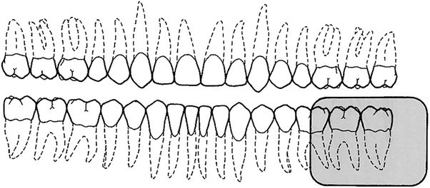
Primary Dentition (3 to 6 Years)
A combination of projections can be used to provide adequate coverage for the pedodontic patient. This examination may consist of two anterior occlusal receptors, two posterior bitewing receptors, and up to four posterior periapical receptors as indicated (Fig. 9-9). For the maxillary and interproximal projections, the child is seated upright with the sagittal plane perpendicular to and the occlusal plane parallel with the floor (horizontal plane). For mandibular projections, except the occlusal, the child is seated upright with the sagittal plane perpendicular. The tragus corner of the mouth line is oriented parallel to the floor. Some find that a panoramic view, rather than the four periapicals, is more informative and results in less exposure to the child (see Chapter 3).
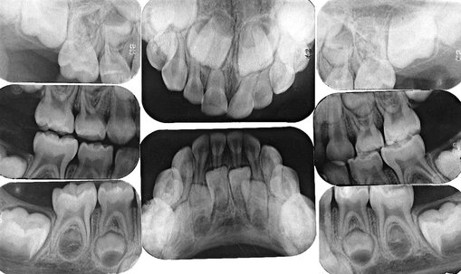
FIG. 9-9 Radiographic examination of primary dentition consists of two anterior occlusal views, four posterior periapical views, and two bitewing views.
Maxillary Anterior Occlusal Projection.: A No. 2 receptor should be placed in the mouth with its long axis perpendicular to the sagittal plane and the pebbled surface toward the maxillary teeth. The receptor is centered on the midline with the anterior border extending just beyond the incisal edges of the anterior teeth. The central ray is directed at a vertical angulation of +60 degrees through the tip of the nose toward the center of the receptor.
Mandibular Anterior Occlusal Projection.: The child should be seated with the head tipped back so that the occlusal plane is about 25 degrees above the plane of the floor. A No. 2 receptor is placed with the long axis perpendicular to the sagittal plane and the pebbled surface toward the mandibular teeth. The central ray is oriented at −30 degrees vertical angulation and through the tip of the chin toward the receptor.
Bitewing Projection.: A No. 0 receptor is used with a paper loop receptor holder. The receptor is placed in the child’s mouth as in the adult premolar bitewing projection. The image field should include the distal half of the canine and the deciduous molars. A positive vertical angulation of +5 to +10 degrees should be used. The horizontal angle is oriented to direct the beam through the interproximal spaces.
Deciduous Maxillary Molar Periapical Projection.: A No. 0 receptor in a modified XCP or BAI bite-block, either with or without the aiming ring and indicator bar, is used. The receptor is positioned in the midline of the palate with the anterior border extending to the maxillary primary canine. The image field of this projection should include the distal half of the primary canine and both primary molars.
Deciduous Mandibular Molar Projection.: A No. 0 receptor is positioned in a modified XCP or BAI bite-block, with or without the aiming ring and indicator bar, between the posterior teeth and tongue. The exposed radiograph should show the distal half of the mandibular primary canine and the primary molar teeth.
Mixed Dentition (7 to 12 Years)
A complete examination of the mixed dentition, if indicated, consists of two incisor periapical views, four canine periapical views, four posterior periapical views, and two or four posterior bitewings (Fig. 9-10). For the maxillary and interproximal projections, the child should be seated upright with the sagittal plane perpendicular and the occlusal plane parallel to the floor. For the mandibular projections, the child should be seated upright with the sagittal plane perpendicular and the ala-tragus line parallel to the floor. XCP instruments are used for larger children. The bisecting-angle bite-blocks may be more comfortable for smaller individuals.

FIG. 9-10 Radiographic examination of mixed dentition consists of two incisor views, four canine views, four posterior views, and two bitewing views.
Maxillary Anterior Periapical Projection.: A No. 1 receptor should be centered on the embrasure between the central incisors in the mouth behind the maxillary central and lateral incisors. The receptor should be centered on the midline.
Mandibular Anterior Periapical Projection.: A No. 1 receptor should be positioned behind the mandibular central and lateral incisors.
Deciduous and Permanent Molar Periapical Projection.: A No. 1 or No. 2 receptor (if the child is large enough) should be positioned with the anterior edge behind the canine.
Posterior Bitewing Projection.: Bitewing projections should be exposed in the premolar region with a No. 1 or No. 2 receptor as previously described, using either bitewing tabs or the Rinn bitewing instrument. Four bitewing projections should be exposed when the second permanent molars have erupted.
Mobile Radiography
There are occasions when it is difficult to have a patient come to a conventional wall-mounted dental x-ray machine. For instance, in remote sites such as nursing homes, hospitals, or at disaster scenes, it could be highly advantageous to have a portable machine that could be taken directly to the patient. Combining such a portable x-ray generator with digital imaging provides rapid, self-contained imaging capability. In recent years such a portable battery-powered x-ray generator has been approved by the Food and Drug Administration (Fig. 9-11). Clinical trials have shown that this unit can be held stable and produces clinically acceptable images. This machine uses a high-frequency, constant potential x-ray generator (60 kilowatt constant potential) and has a short focal spot to skin distance (20 cm). Both these factors allow for short exposure times compared with conventional units. It has a small focus spot (0.4 mm). The operator dose is mitigated by the use of internal shielding materials in the unit to reduce leakage exposure and a shield on the aiming cylinder to minimize backscatter from the patient. These units are approved for use in many but not all states in the United States.
Special Considerations
The radiographic procedures that have been described in this chapter are for the “well” patient. These procedures may need to be modified for patients who have unusual difficulties. Specific modifications depend on the patient’s physical and emotional characteristics. As with any dental procedure, however, the dental assistant begins the examination by showing appreciation of the patient’s condition and sympathy for any problems that might occur for either of them. If the assistant is kind but firm, the patient’s confidence increases, which helps the patient relax and cooperate. Following are a few conditions and circumstances that may be encountered, with some recommendations and suggestions that may help the clinician achieve an adequate radiographic examination.
INFECTION
Infection in the orofacial structures may result in edema and lead to trismus of some of the muscles of mastication. As a result, intraoral radiography may be painful to the patient and difficult for both the patient and radiologist. Under such circumstances extraoral or occlusal techniques may offer the only possibility of an examination. The choice of a specific extraoral projection depends on the condition and the areas to be examined. Although the resulting radiograph may not be ideal in many respects, it usually provides more useful information than the diagnostician would have without it. In the case of edema in an area to be examined, exposure time should be increased to compensate for the tissue swelling.
TRAUMA
A patient who has undergone trauma may have a dental or facial fracture. Dental fractures are best appreciated by using periapical or occlusal radiographs. Special care must be taken when making these views because of the condition of the patient. Skeletal fractures are usually best seen with panoramic or other extraoral views or a computed tomography examination. In some cases patients with fractures of the facial skeleton may be bedridden because of involvement of other injuries. Consequently, an extraoral radiographic examination with the patient in the supine position is necessary. However, the circumstances need not compromise the techniques, and satisfactory intraoral radiographs can be produced if the proper relative positions of the tube, patient, and receptor are observed.
PATIENTS WITH MENTAL DISABILITIES
Patients with mental disabilities may cause some difficulty for the radiologist who is attempting an examination. The difficulty usually is the result of the patient’s lack of coordination or inability to comprehend what is expected. However, when the radiographic examination is performed speedily, unpredictable moves by the patient can be minimized. In some cases sedation may be required.
PATIENTS WITH PHYSICAL DISABILITIES
Patients with physical disabilities (e.g., loss of vision, loss of hearing, loss of the use of any or all extremities, congenital defects such as cleft palate) may require special handling during a radiographic examination. These patients usually are cooperative and eager to assist. They may be accustomed to so much discomfort and inconvenience that their tolerance level is high, and they are not challenged by the relatively slight irritation represented by the x-ray procedures. Generally, intraoral and extraoral radiographic examinations may be performed for these patients if a good rapport between the patient and radiology technician is established and maintained. Members of the patient’s family often are very helpful in assisting the patient into and out of the examination chair and in receptor positioning and holding, inasmuch as they usually are familiar with the patient’s condition and accustomed to coping with it.
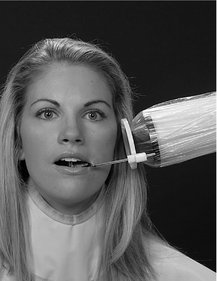
GAG REFLEX
Occasionally, patients who need a radiographic examination manifest a gag reflex at the slightest provocation. These patients usually are very apprehensive and frightened by unknown procedures; others simply seem to have very sensitive tissue that precipitates a gag reflex when stimulated. This sensitivity is manifested when the receptor is placed in the oral cavity. To overcome this disability, the radiologist should make an effort to relax and reassure the patient. The radiologist can describe and explain the procedures. Often gagging can be controlled if the operator bolsters the patient’s confidence by demonstrating technical competence and showing authority tempered with compassion. The gag reflex often is worse when a patient is tired; therefore it is advisable to perform the examination in the morning, when the individual is well rested, especially in the case of children.
Stimulating the posterior dorsum of the tongue or the soft palate usually initiates the gag reflex. Consequently, during the placement of the receptor, the tongue should be very relaxed and positioned well to the floor of the mouth. This can be accomplished by asking the patient to swallow deeply just before opening the mouth for placement of the receptor. (The dentist should never mention the tongue, nor ask patients to relax the tongue; this usually makes them more conscious of it and precipitates involuntary movements.) The receptor is carried into the mouth parallel to the occlusal plane. When the desired area is reached, the receptor is rotated with a decisive motion, bringing it into contact with the palate or the floor of the mouth. Sliding it along the palate or tongue is likely to stimulate the gag reflex. Also, the dentist must keep in mind that the longer the receptor stays in the mouth, the greater the possibility that the patient will start to gag. The patient should be advised to breathe rapidly through the nose because mouth breathing usually aggravates this condition.
Any little exercise that can be devised that does not interfere with the x-ray examination but shifts the patient’s attention from the receptor and the mouth is likely to relieve the gag reaction. Asking patients to hold their breath often can create such a distraction or to keep a foot or arm suspended during receptor placement and exposure. In extreme cases, topical anesthetic agents in mouthwashes or spray can be administered to produce temporary numbness of the tongue and palate to reduce gagging. However, in our experience this procedure gives limited results. The most effective approach is to reduce apprehension, minimize tissue irritation, and encourage rapid breathing through the nose. If all measures fail, an extraoral examination may be the only means, short of administering general anesthesia, to examine the patient radiographically.
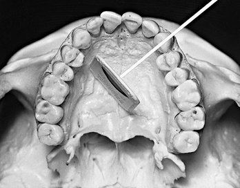
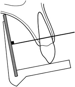
RADIOGRAPHIC TECHNIQUES FOR ENDODONTICS
Radiographs are essential to the practice of endodontics. Not only are they indispensable for determining the diagnosis and prognosis of pulp treatment, they also are the most reliable method of managing endodontic treatment. The presence of a rubber dam, rubber dam clamp, and root canal instruments may complicate an intraoral periapical examination by impairing proper receptor positioning and aiming cylinder angulation. Despite these obstacles, certain requirements must be observed:
1. The tooth being treated must be centered in the image.
2. The receptor must be positioned as far from the tooth and apex as the region permits to ensure that the apex of the tooth and some periapical bone are apparent on the radiograph.
For maxillary projections, the patient is seated so that the sagittal plane is perpendicular and the occlusal plane is parallel to the floor. For mandibular projections, the patient is seated upright with the sagittal plane perpendicular and the tragus-to-corner of the mouth line parallel to the floor. Specially designed receptor holders for endodontic radiographs are available (Fig. 9-12). These instruments fit over files, clamps, and the rubber dam without touching the subject tooth. The aiming cylinder is aligned so as to direct the central ray perpendicular to the center of the receptor.
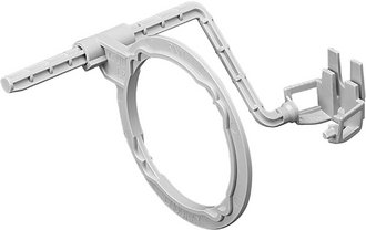
FIG. 9-12 EndoRay receptor holder used for endodontic radiographs. (Courtesy Dentsply Rinn, Elgin, Ill.)
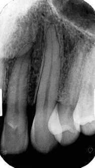
Often a single radiograph of a multirooted tooth made at the normal vertical and horizontal projection does not display all the roots. In these cases, when it is necessary to separate the roots on multirooted teeth, a second projection may be made. The horizontal angulation is altered 20 degrees mesially for maxillary premolars, 20 degrees mesially or distally for maxillary molars, or 20 degrees distally for an oblique projection of mandibular molar roots.
If a sinus tract is encountered, its course is tracked by threading a No. 40 gutta-percha cone through the tract before the radiograph is made. It also is possible to localize and determine the depth of periodontal defects with this gutta-percha tracking technique.
A final radiograph of the treated tooth is made to demonstrate the quality of the root canal filling and the condition of the periapical tissues after removal of the clamp and rubber dam.
PREGNANCY
Although a fetus is sensitive to ionizing radiation, the amount of exposure received by an embryo or fetus during dental radiography is extremely low. No incidences have been reported of damage to a fetus from dental radiography. Regardless, prudence suggests that such radiographic examinations be kept to a minimum consistent with the mother’s dental needs. As with any patient, radiographic examination is limited during pregnancy to cases with a specific diagnostic indication. With the low patient dose afforded by use of optimal radiation safety techniques (see Chapter 3), an intraoral or extraoral examination can be performed whenever a reasonable diagnostic requirement exists.
EDENTULOUS PATIENTS
Radiographic examination of edentulous patients is important, whether the area of interest is one tooth or an entire arch. These areas may contain roots, residual infection, impacted teeth, cysts, or other pathologic entities that may adversely affect the usefulness of prosthetic appliances or the patient’s health. After a determination has been made that these entities are not present, repeated examinations to detect them are not warranted in the absence of signs or symptoms.
If available, a panoramic examination of the edentulous jaws is most convenient. If abnormalities of the alveolar ridges are identified, the higher resolution of periapical receptor is used to make intraoral projections to supplement the panoramic examination.
In a completely or partly edentulous patient, a receptor-holding device is used for intraoral radiography of the alveolar ridges. Placement of the receptor-holding instrument may be complicated by its tipping into the voids normally occupied by the crowns of the missing teeth. To manage this difficulty, cotton rolls are placed between the ridge and the receptor holder, supporting the holder in a horizontal position. An orthodontic elastic band to hold cotton rolls to the bite-block on the receptor holder often is useful when several such projections must be exposed. With elastics, it is simple to maneuver the cotton rolls into the areas that require support. The patient may steady the receptor-holding instrument with a hand or an opposing denture.
If panoramic equipment is not available, an examination consisting of 14 intraoral views provides an excellent survey. The exposure required for an edentulous ridge is approximately 25% less than that for a dentulous ridge. This examination consists of seven projections in each jaw (adult No. 2 receptor) as follows:
Adriaens, PA, De Boever, J, Vande Velde, F. Comparison of intra-oral long-cone paralleling radiographic surveys and orthopantomographs with special reference to the bone height. J Oral Rehabil. 1982;9:355–365.
Biggerstaff, RH, Phillips, JR. A quantitative comparison of paralleling long-cone and bisection-of-angle periapical radiography. Oral Surg Oral Med Oral Pathol. 1976;62:673–677.
Dubrez, B, Jacot-Descombes, S, Cimasoni, G. Reliability of a paralleling instrument for dental radiographs. Oral Surg Oral Med Oral Pathol Oral Radiol Endod. 1995;80:358–364.
Forsberg, J, Halse, A. Radiographic simulation of a periapical lesion comparing the paralleling and the bisecting-angle techniques. Int Endod J. 1994;27:133–138.
Iannucci, J, Jansen Howerton, L. Dental radiography: principles and techniques, ed 3. St. Louis: Saunders; 2006.
Scandrett, FR, Tebo, HG, Miller, JT, et al. Radiographic examination of the edentulous patient, 1: review of the literature and preliminary report comparing three methods. Oral Surg Oral Med Oral Pathol. 1973;35:266–274.
Schulze, RK, d’Hoedt, B. A method to calculate angular disparities between object and receptor in paralleling technique. Dentomaxillofac Radiol. 2002;31:32–38.
Weclew, TV. Comparing the paralleling extension cone technique and the bisecting angle technique. J Acad Gen Dent. 1974;22:18–20.