Radiation Physics
One atom says to a friend, “I think I lost an electron.” The friends replies, “Are you sure?” “Yes,” says the first atom, “I’m positive.”
Composition of Matter
Matter is anything that has mass and occupies space. Matter occurs in three states: solid, liquid, and gas. Atoms, the fundamental units of matter, cannot be subdivided by chemical methods although they may be composed of many smaller (subatomic) particles. Bohr viewed the atom as a miniature solar system with a nucleus at the center and revolving electrons (Fig. 1-1). Although this classical view of the atom has the virtue of being easily understood, it has been replaced in recent decades by the Standard Model, which describes fundamental particles, and the Quantum Mechanical Model, which describes the arrangement of electrons in an atom.
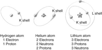
FIG. 1-1 Atomic structures of hydrogen, helium, and lithium showing electrons orbiting nuclei containing neutrons and protons as described by Bohr in the early twentieth century.
According to the Standard Model, there are 12 types of fundamental matter particles plus their corresponding antiparticles (Table 1-1). These particles are considered to be fundamental because current experiments show that they have no inner structure and cannot be divided. These fundamental particles consist of six types of quarks and six types of leptons and their antiparticles (particles having an opposite charge but otherwise identical to quarks and leptons). Quarks only exist in association with other quarks, never as solitary particles. Neutrons and protons are made of quarks. Unlike quarks, leptons exist only as solitary particles. The stable leptons are electrons and neutrinos. All visible matter in the universe (that is, all stable matter) is made of up quarks, down quarks, and electrons. Antimatter particles are rare and highly unstable because when they interact with matter, they mutually annihilate into pure energy. The universe is made of 24% matter and 76% dark energy. Only 5% of the matter is in the form of atoms and neutrinos. The nature of the rest of the matter, and of dark energy, is unknown.
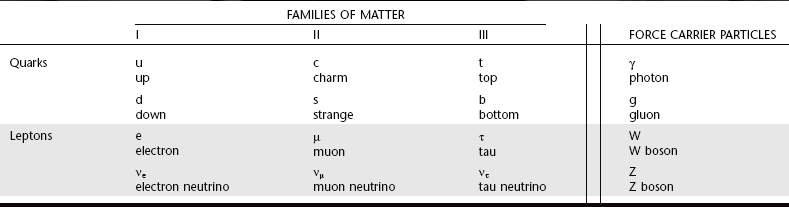
In addition to matter particles, the Standard Model describes force carrier particles—particles that mediate interactions between matter particles. They are the means by which matter (quarks and leptons) interacts without touching, such as through magnetism, light, and electrostatic attraction and repulsion. Photons mediate the electromagnetic force, W and Z bosons mediate the weak nuclear force (associated with beta decay), and gluons mediate the strong nuclear force that binds nuclei together. Gravity is speculated to be mediated by gravitons, a fourth type of force particle (but not part of the Standard Model).
ATOMIC STRUCTURE
In all atoms except hydrogen, the nucleus consists of positively charged protons and neutral neutrons. A hydrogen nucleus contains a single proton. Protons and neutrons in turn are made of quarks (Fig. 1-2). Protons (with a charge of 1) consist of two up quarks (charge  each) and one down quark (charge
  ). Neutrons are made of one up quark and two down quarks and thus are neutral. Although the positively charged protons repel each other, the nucleus does not fly apart because it is held together by the strong nuclear force, the rapid exchange of gluons. The strong nuclear force overwhelms the repulsive electromagnetic effect at the incredibly short distances inside an atomic nucleus.
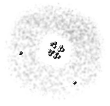
FIG. 1-2 Modern view of helium atom showing nucleus with two protons, each composed of two up quarks (U) and one down quark (D), two neutrons, each made of one up quark and two down quarks, and two surrounding electrons within a spherical orbital.
The number of protons in the nucleus determines the identity of an element. This is its atomic number (Z), the nuclear charge. Each of the more than 100 elements has a specific atomic number, a corresponding number of orbital electrons in the ground state, and unique chemical and physical properties. Nearly the entire mass of the atom consists of the protons and neutrons in the nucleus. The total number of protons and neutrons in the nucleus of an atom is its atomic mass (A).
Electron Orbitals
The Quantum Mechanical Model describes contemporary understanding of the arrangement of electrons in an atom. Beginning with the work of Schrödinger, physicists saw electrons as being small particles that exhibit particle-like properties (e.g., they have mass) and wavelike properties (e.g., they generate interference patterns). The previous concept of electrons circling around nuclei in two-dimensional orbits has been replaced by the concept of electrons existing in three-dimensional volumes called orbitals. Orbitals represent the probability locations of the electron in space at any instant in time, the regions in which the electron is most likely to exist. Each kind of orbital is characterized by a set of quantum numbers n, l, and m. The principal quantum number (n) describes the size of the orbital, the average distance of the electron from the nucleus. The angular momentum quantum number (l) describes the shape of the orbital (l can never be greater than n − 1). The letters s, p, d, f, g, and h are used to describe orbital shapes and correspond with angular momentum values of 0, 1, 2, 3, 4, and 5, respectively. The s-type orbital is spherical (Fig. 1-3). The s-type orbitals are the first to be filled in every element. Next are the p-type orbitals, which are bilobed and centered on the nucleus. Boron is the first element to contain an electron in a p orbital. Next are the d-type orbitals, which consist of four lobes arranged around the nucleus or they are bilobed with a ring. Scandium is the first element to contain an electron in a d orbital. The magnetic quantum number (m) describes the orientation of an orbital in space. In an atom with many electrons the electron clouds of one orbital are superimposed with those of other orbitals. No known atom has more than seven orbitals. Only two electrons may occupy an orbital. Electrons occupy the lowest energy available orbitals first (lowest principal quantum number then the lowest angular momentum). Finally, for the first 18 elements, the orbitals fill up first each of the available orientations (m) one at a time so that their spins are unpaired.
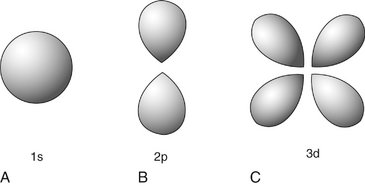
FIG. 1-3 Electron orbitals look like clouds of varying density, probability plots of the location of the electron. A, The s-type electron orbital is spherical and centered around the nucleus. B, p-type electron orbitals are bilobed and centered around the nucleus. C, Four of the five d-type electron orbitals are made up of four lobes, centered on the nucleus, the other is bilobed with an encircling ring.
In all atoms there is an electrostatic attraction between the positively charged nucleus and its surrounding negatively charged electrons. The amount of energy required to remove an electron from a given orbital must exceed the electrostatic force of attraction between it and the nucleus. This is called the electron binding energy of the electron (or ionization energy) and is specific for each orbital of each element. Electrons in the 1s orbital of a given element have the greatest binding energy because they are closest to the nucleus. The binding energy of the electrons in each successively larger orbital decreases. For an electron to move from a specific orbital to another orbital farther from the nucleus, energy must be supplied in an amount equal to the difference in binding energies between the two orbitals. In contrast, in moving an electron from an outer orbital to one closer to the nucleus, energy is lost and given up in the form of electromagnetic radiation (see “Characteristic Radiation,” p. 10).
IONIZATION
When the number of electrons in an atom is equal to the number of protons in its nucleus, the atom is electrically neutral. If such an atom loses an electron, the nucleus becomes a positive ion and the free electron a negative ion. This process of forming an ion pair is termed ionization. To ionize an atom requires sufficient energy to overcome the electrostatic force binding the electrons to the nucleus. The binding energy of an electron is related to the atomic number of the atom and the orbital type. Large atomic number elements (high Z) have more protons in their nucleus and thus bind electrons in any give orbital more tightly than do smaller-Z elements. Within a given atom, electrons in the inner orbitals are more tightly bound than the more distant outer orbitals. Tightly bound electrons require the energy of x rays or high-energy particles to remove them, whereas loosely bound electrons can be displaced by ultraviolet radiation. However, nonionizing radiations, such as visible light, infrared, and microwave radiation, and radio waves do not have sufficient energy to remove bound electrons from their orbitals.
Nature of Radiation
Radiation is the transmission of energy through space and matter. It may occur in two forms: particulate and electromagnetic.
RADIOACTIVITY
Small atoms have roughly equal numbers of protons and neutrons, whereas larger atoms tend to have more neutrons than protons. This makes them unstable and they may break up, releasing α or β particles or γ rays. This process is called radioactivity. When a radioactive atom releases an α or β particle, the atom is transmuted into another element. α Particles are helium nuclei consisting of two protons and two neutrons. They result from the radioactive decay of many large atomic number elements. Because of their double positive charge and heavy mass, α particles densely ionize matter through which they pass. Accordingly, they quickly give up their energy and penetrate only a few micrometers of body tissue. (An ordinary sheet of paper absorbs them.) After stopping, α particles acquire two electrons and become neutral helium atoms.
When a neutron in a radioactive nucleus decays, it produces a proton, a β particle, and a neutrino. β Particles are otherwise identical to electrons. High-speed β particles are not densely ionizing; thus, they are able to penetrate matter to a greater depth than α particles can, up to a maximum of 1.5 cm in tissue. This deeper penetration occurs because β particles are smaller and lighter and carry a single negative charge; therefore they have a much lower probability of interacting with matter than do α particles. β Particles are used in radiation therapy for treatment of some skin cancers.
The capacity of particulate radiation to ionize atoms depends on its mass, velocity, and charge. The rate of loss of energy from a particle as it moves along its track through matter (tissue) is its linear energy transfer (LET). A particle loses kinetic energy each time it ionizes adjacent matter. The greater its physical size and charge and the lower its velocity, the greater is its LET. For example, α particles, with their high charge and low velocity, are densely ionizing, lose their kinetic energy rapidly, and thus have a high LET. β Particles are much less densely ionizing because of their lighter mass and lower charge; thus they have a lower LET. High LET radiations concentrate their ionization along a short path, whereas low LET radiations produce ion pairs much more sparsely over a longer path length.
The third type of radioactivity is γ decay. γ Rays are photons, a form of electromagnetic radiation (see later). They result as part of a decay chain where a massive nucleus produced by fission converts from an excited state to a lower-level ground state.
ELECTROMAGNETIC RADIATION
Electromagnetic radiation is the movement of energy through space as a combination of electric and magnetic fields. It is generated when the velocity of an electrically charged particle is altered. γ Rays, x rays, ultraviolet rays, visible light, infrared radiation (heat), microwaves, and radio waves are all examples of electromagnetic radiation (Fig. 1-4). γ Rays originate in the nuclei of radioactive atoms. They typically have greater energy than do x rays. X rays, in contrast, are produced extranuclearly from the interaction of electrons with large atomic nuclei in x-ray machines. The types of radiation in the electromagnetic spectrum may be ionizing or nonionizing, depending on their energy.
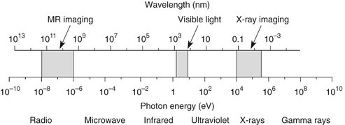
FIG. 1-4 Electromagnetic spectrum showing the relationship among wavelength, photon energy, and physical properties of various portions of the spectrum. Photons with shorter wavelengths have higher energy. Photons used in dental radiography have a wavelength of 0.1 to 0.001 nanometers.
Quantum theory considers electromagnetic radiation as small bundles of energy called photons. Each photon travels at the speed of light and contains a specific amount of energy. The unit of photon energy is the electron volt (eV), the amount of energy acquired by one electron accelerating through a potential difference of 1 volt (1.602 × 10⁻¹⁹ joules). The relationship between wavelength and photon energy is as follows:

where E is energy in kiloelectron volts (keV), h is Planck’s constant (6.626 × 10⁻³⁴ joule-seconds or 4.3 × 10⁻¹⁸ keV), c is the velocity of light, and λ is wavelength in nanometers. This expression may be simplified to the following:

Some properties of electromagnetic radiation are best expressed by quantum theory, whereas others are most successfully described by wave theory. The quantum theory of radiation has been successful in correlating experimental data on the interaction of radiation with atoms, the photoelectric effect, and the production of x rays. The wave theory of electromagnetic radiation maintains that radiation is propagated in the form of waves, not unlike the waves resulting from a disturbance in water. Such waves consist of electric and magnetic fields oriented in planes at right angles to one another that oscillate perpendicular to the direction of motion (Fig. 1-5). All electromagnetic waves travel at the velocity of light (c = 3.0 × 10⁸ m/sec) in a vacuum. Waves of all kinds exhibit the properties of wavelength (λ) and frequency (ν) and are related as follows:
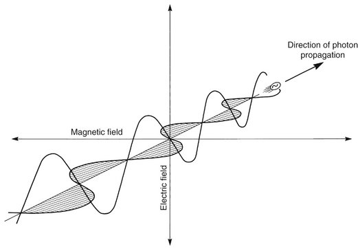
where λ is in meters and ν is in cycles per second (hertz). Wave theory is more useful for considering radiation in bulk when millions of quanta are being examined, as in experiments dealing with refraction, reflection, diffraction, interference, and polarization.
High-energy photons such as x rays and γ rays are typically characterized by their energy (electron volts), medium-energy photons (e.g., visible light and ultraviolet waves) by their wavelength (nanometers), and low-energy photons (e.g., AM and FM radio waves) by their frequency (KHz and MHz).
X-Ray Machine
The primary components of an x-ray machine are the x-ray tube and its power supply. The x-ray tube is positioned within the tube head, along with some components of the power supply (Fig. 1-6). Often the tube is recessed within the tube head to improve the quality of the radiographic image (see Chapter 4). The tube head is supported by an arm that is usually mounted on a wall. A control panel allows the operator to adjust the time of exposure and often the energy and exposure rate of the x-ray beam.
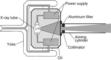
FIG. 1-6 Tube head (including the recessed x-ray tube), components of the power supply, and the oil that conducts heat away from the x-ray tube. Path of useful x-ray beam from anode through filter and collimator to end of aiming cylinder shown in blue.
X-RAY TUBE
An x-ray tube is composed of a cathode and an anode situated within an evacuated glass envelope or tube (Fig. 1-7). Electrons stream from a filament in the cathode to a target in the anode, where they produce x rays. For the x-ray tube to function, a power supply is necessary to (1) heat the cathode filament to generate electrons and (2) establish a high-voltage potential between the anode and cathode to accelerate the electrons toward the anode.
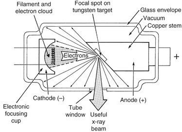
Cathode
The cathode (see Fig. 1-7) in an x-ray tube consists of a filament and a focusing cup. The filament is the source of electrons within the x-ray tube. It is a coil of tungsten wire about 2 mm in diameter and 1 cm or less in length. It is mounted on two stiff wires that support it and carry the electric current. These two mounting wires lead through the glass envelope and connect to both the high- and low-voltage electrical sources. The filament is heated to incandescence by the flow of current from the low-voltage source and emits electrons at a rate proportional to the temperature of the filament.
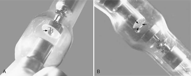
The filament lies in a focusing cup (Fig. 1-8, A; see also Fig. 1-7), a negatively charged concave reflector made of molybdenum. The parabolic shape of the focusing cup electrostatically focuses the electrons emitted by the filament into a narrow beam directed at a small rectangular area on the anode called the focal spot (Fig. 1-8, B; see also Fig. 1-7). The electrons move in this direction because they are both repelled by the negatively charged cathode and attracted to the positively charged anode. The x-ray tube is evacuated to prevent collision of the fast-moving electrons with gas molecules, which would significantly reduce their speed. The vacuum also prevents oxidation, “burnout,” of the filament.
Anode
The anode consists of a tungsten target embedded in a copper stem (see Fig. 1-7). The purpose of the target in an x-ray tube is to convert the kinetic energy of the colliding electrons into x-ray photons. The target is made of tungsten, an element that has several characteristics of an ideal target material. It has a high atomic number (74), a high melting point, high thermal conductivity, and low vapor pressure at the working temperatures of an x-ray tube. The conversion of the kinetic energy of the electrons into x-ray photons is an inefficient process with more than 99% of the electron kinetic energy converted to heat. A target made of a high atomic number material is most efficient in producing x rays. Because heat is generated at the anode, the requirement for a target with a high melting point is clear. Tungsten also has high thermal conductivity, thus readily dissipating its heat into the copper stem. Finally, the low vapor pressure of tungsten at high temperatures helps maintain the vacuum in the tube at high operating temperatures. The tungsten target is typically embedded in a large block of copper. Copper, also a good thermal conductor, removes heat from the tungsten, thus reducing the risk of the target melting. Additionally, insulating oil between the glass envelope and the housing of the tube head carries heat away from the copper stem. This type of anode is a stationary anode because it has no moving parts.
The focal spot is the area on the target to which the focusing cup directs the electrons and from which x rays are produced. The sharpness of a radiographic image increases as the size of the focal spot decreases (see Chapter 4). The heat generated per unit target area, however, becomes greater as the focal spot decreases in size. To take advantage of a small focal spot while distributing the electrons over a larger area of the target, the target is placed at an angle to the electron beam (Fig. 1-9). The apparent size of the focal spot seen from a position perpendicular to the electron beam (the effective focal spot) is smaller than the actual focal spot size. Typically, the target is inclined about 20 degrees to the central ray of the x-ray beam. This causes the effective focal spot to be approximately 1 × 1 mm, as opposed to the actual focal spot, which is about 1 × 3 mm. This results in a small apparent source of x rays and thus an increase in the sharpness of the image (see Fig. 4-2), with a larger actual focal spot size to improve heat dissipation.
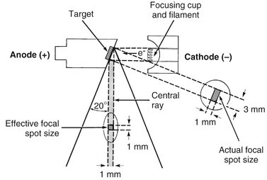
FIG. 1-9 The angle of the target to the central ray of the x-ray beam has a strong influence on the apparent size of the focal spot. The projected effective focal spot is much smaller than the actual focal spot size.
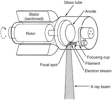
Another method of dissipating the heat from a small focal spot is to use a rotating anode. In this case the tungsten target is in the form of a beveled disk that rotates when the tube is in operation (Fig. 1-10). As a result, the electrons strike successive areas of the target, widening the focal spot by an amount corresponding to the circumference of the beveled disk, thus distributing the heat over this extended area. The focal spot of a stationary tube is now a focal track in rotating anode machines. Narrow focal tracks in rotating anode tubes can be used with tube currents of 100 to 500 milliamperes (mA), 10 to 50 times that possible with stationary targets. The target and rotor (armature) of the motor lie within the x-ray tube, and the stator coils (which drive the rotor at about 3000 revolutions per minute) lie outside the tube. Such rotating anodes are not used in intraoral dental x-ray machines but may be used in tomographic or cephalometric units and are always used in medical computed tomography x-ray machines, which require high radiation output.
POWER SUPPLY
The primary functions of the power supply of an x-ray machine are to (1) provide a low-voltage current to heat the x-ray tube filament and (2) generate a high potential difference between the anode and cathode. The x-ray tube and two transformers lie within an electrically grounded metal housing called the head of the x-ray machine. An electrical insulating material, usually oil, surrounds the tube and transformers.
Tube Current
The tube current is the flow of electrons through the tube; that is, from the cathode filament, across the tube to the anode, and then back to the filament. The filament transformer (Fig. 1-11) reduces the voltage of the incoming alternating current (AC) to about 10 volts in the filament circuit. This voltage is regulated by the filament current control (mA selector), which adjusts the resistance and thus the current flow through the filament. This in turn regulates the filament temperature and thus the number of electrons emitted. The mA setting on the filament current control actually refers to the tube current, typically about 10 mA, which is measured by the milliammeter. This is not the same as the current in the filament circuit.
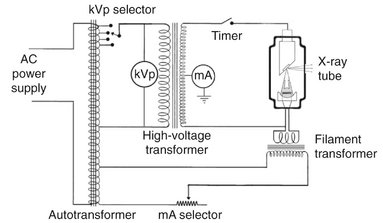
FIG. 1-11 Schematic of dental x-ray machine circuitry and x-ray tube with the major components labeled.
Notice also that the tube current is dependent on the tube voltage; as the voltage increases between the anode and cathode, so does the current flow. The hot filament releases electrons, creating a negative space charge around the filament. When the filament wire is positive, the released electrons stay near the filament. The increasingly negative space charge impedes the further release of electrons. When the anode becomes positive, it attracts electrons from the filament, the space charge is reduced, and increasing numbers of electrons are released from the filament, thereby increasing the tube current. The higher the voltage, the greater this effect.
Tube Voltage
A high voltage is required between the anode and cathode to give electrons sufficient energy to generate x rays. The actual voltage used on an x-ray machine is adjusted with the autotransformer (see Fig. 1-11). By using the kilovolt peak (kVp) selector, the operator adjusts the autotransformer and converts the primary voltage from the input source into the desired secondary voltage. The selected secondary voltage is applied to the primary winding of the high-voltage transformer, which boosts the peak voltage of the incoming line current (110 V) up to 60,000 to 100,000 V (60 to 100 kV). This boosts the peak energy of the electrons passing through the tube to as high as 60 to 100 keV and provides them sufficient energy to generate x rays. The kVp dial thus selects the peak operating voltage between the anode and cathode.
Because the polarity of the line current alternates (60 cycles per second), the polarity of the x-ray tube alternates at the same frequency (Fig. 1-12, A). When the polarity of the voltage applied across the tube causes the target anode to be positive and the filament to be negative, the electrons around the filament accelerate toward the positive target and current flows through the tube (Fig. 1-12, B). Because the line voltage varies continuously, so does the voltage potential between the anode and cathode.
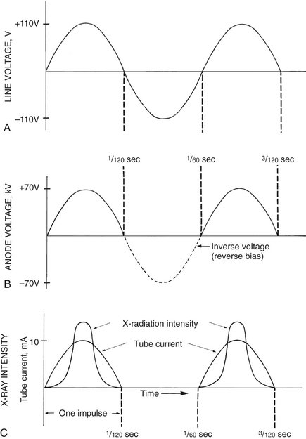
FIG. 1-12 A, A 60-cycle AC line voltage at autotransformer. B, Voltage at the anode varies up to the kVp setting (70 in this case). C, The intensity of radiation produced at the anode increases as the anode voltage increases. (Modified from Johns HE, Cunningham JR: The physics of radiology, ed 3, Springfield, Ill, 1969, Charles C Thomas.)
The operating voltage of an x-ray machine is stated as the kVp. As the tube voltage is increased, the speed of the electrons moving toward the anode increases. When the electrons strike the focal spot of the target, some of their energy converts to x-ray photons. X rays are produced at the target with greatest efficiency when the voltage applied across the tube is high. Therefore the intensity of x-ray pulses tends to be sharply peaked at the center of each cycle (Fig. 1-12, C). During the following half (or negative half) of each cycle, the filament becomes positive and the target negative (see Fig. 1-12, B). At these times the electrons do not flow across the gap between the two elements of the tube. This half of the cycle is called inverse voltage or reverse bias (see Fig. 1-12, B). No x rays are generated during this half of the voltage cycle (see Fig. 1-12, C). Therefore when an x-ray tube is powered with 60-cycle AC, 60 pulses of x rays are generated each second, each having a duration of  second. This type of power supply circuitry, in which the alternating high voltage is applied directly across the x-ray tube, limits x-ray production to half the AC cycle and is called self-rectified or half-wave rectified. Almost all conventional dental x-ray machines are self-rectified.
Some dental x-ray manufacturers produce machines that replace the conventional 60-cycle AC, half-wave rectified power supply with a full-wave rectified, high-frequency power supply. This results in an essentially constant potential between the anode and cathode. The result is that the mean energy of the x-ray beam produced by these x-ray machines is higher than that from a conventional half-wave rectified machine operated at the same voltage. For a given voltage setting and radiographic density, the images resulting from these constant-potential machines have a longer contrast scale and the patient receives a lower dose compared with conventional x-ray machines.
TIMER
A timer is built into the high-voltage circuit to control the duration of the x-ray exposure (see Fig. 1-11). The electronic timer controls the length of time that high voltage is applied to the tube and therefore the time during which tube current flows and x rays are produced. Before the high voltage is applied across the tube, however, the filament must be brought to operating temperature to ensure an adequate rate of electron emission. Subjecting the filament to continuous heating at normal operating current shortens its life. To minimize filament damage, the timing circuit first sends a current through the filament for about half a second to bring it to the proper operating temperature and then applies power to the high-voltage circuit. In some circuit designs, a continuous low-level current passing through the filament maintains it at a safe low temperature, thereby further shortening the delay to preheat the filament. For these reasons an x-ray machine may be left on continuously during working hours.
Some x-ray machine timers are calibrated in fractions of a second, whereas others are expressed as number of impulses in an exposure (e.g., 3, 6, 9, 15). The number of impulses divided by 60 (the frequency of the power source) gives the exposure time in seconds. Thus a setting of 30 impulses means that there will be 30 impulses of radiation equivalent to a half-second exposure.
TUBE RATING AND DUTY CYCLE
X-ray tubes produce heat at the target while in operation. The heat buildup at the anode is measured in heat units (HU), where HU = kVp × mA × seconds. The heat storage capacity for anodes of dental diagnostic tubes is approximately 20 kHU. Heat is removed from the target by conduction to the copper anode and then to the surrounding oil and tube housing and by convection to the atmosphere.
Each x-ray machine comes with a tube rating chart that describe the longest exposure time the tube can be energized for a range of voltages (kVp) and tube current (mA) values without risk of damage to the target from overheating. These tube ratings generally do not impose any restrictions on tube use for intraoral radiography. If a dental x-ray unit is used for extraoral exposures, however, it is wise to mount the tube-rating chart by the machine for easy reference. Duty cycle relates to the frequency with which successive exposures can be made. The interval between successive exposures must be long enough for heat dissipation. This characteristic is a function of the size of the anode and the method used to cool it.
Production of X Rays
Most high-speed electrons traveling from the filament to the target interact with target electrons and release their energy as heat. Occasionally, however, electrons convert their kinetic energy into x-ray photons by the formation of bremsstrahlung and characteristic radiation.
BREMSSTRAHLUNG RADIATION
The sudden stopping or slowing of high-speed electrons by tungsten nuclei in the target produces bremsstrahlung photons, the primary source of radiation from an x-ray tube. (Bremsstrahlung means “braking radiation” in German.) Occasionally electrons from the filament directly hit the nucleus of a target atom. When this happens, all the kinetic energy of the electron is transformed into a single x-ray photon (Fig. 1-13, A). The energy of the resultant photon (in keV) is thus numerically equal to the energy of the electron, that is, the voltage applied across the x-ray tube at that instant.
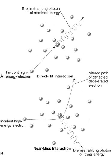
FIG. 1-13 Bremsstrahlung radiation is produced by the direct hit of an electron on a nucleus in the target (A) or more frequently, by the passage of an electron near a nucleus, which results in electrons being deflected and decelerated (B).
More frequently, high-speed electrons have near or wide misses with atomic nuclei (see Fig. 1-13, B). In these interactions, the electron is attracted toward the positively charged nuclei, its path is altered towards the nucleus, and it loses some of its velocity. This deceleration causes the electron to lose kinetic energy that is given off in the form of many new photons. The closer the high-speed electron approaches the nuclei, the greater is the electrostatic attraction between the nucleus and the electron, braking effect, and energy of the resulting bremsstrahlung photons.
Bremsstrahlung interactions generate x-ray photons with a continuous spectrum of energy. The energy of an x-ray beam is usually described by identifying the peak operating voltage (in kVp). A dental x-ray machine operating at a peak voltage of 70 kVp, for example, applies a fluctuating voltage of up to 70 kVp across the tube. This tube therefore produces a continuous spectrum of x-ray photons with energies ranging to a maximum of 70 keV (Fig. 1-14). The reasons for this continuous spectrum are as follows:
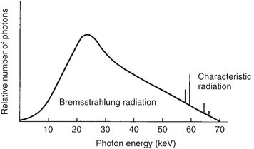
FIG. 1-14 Spectrum of photons emitted from an x-ray beam generated at 70 kVp. The vast preponderance of radiation is bremsstrahlung, with a minor addition of characteristic radiation.
1. The continuously varying voltage difference between the target and filament, which is characteristic of half-wave rectification, causes the electrons striking the target to have varying levels of kinetic energy.
2. The bombarding electrons pass at varying distances around tungsten nuclei and are thus deflected to varying extents. As a result, they give up varying amounts of energy in the form of bremsstrahlung photons.
3. Many electrons participate in many bremsstrahlung interactions in the target before losing all their kinetic energy. As a consequence, an electron carries differing amounts of energy at the time of each interaction with a tungsten nucleus that results in the generation of an x-ray photon.
CHARACTERISTIC RADIATION
Characteristic radiation contributes only a small fraction of the photons in an x-ray beam. It occurs when an incident electron ejects an inner electron from the tungsten target. When this happens, an electron from an outer orbital is quickly attracted to the void in the deficient inner orbital (Fig. 1-15). When the outer-orbital electron replaces the displaced electron, a photon is emitted with an energy equivalent to the difference in the two orbital binding energies. The energies of characteristic photons are discrete because they represent the difference of the energy levels of electron orbital levels and hence are characteristic of the target atoms.
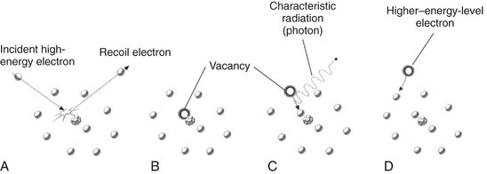
FIG. 1-15 Characteristic radiation. A, An incident electron ejects an electron from in an inner orbital creating a photoelectron and a vacancy. B, An electron from an outer orbital fills this vacancy. C, A photon is emitted with energy equal to the difference in energy levels between the two orbitals. D, Electrons from various orbitals may be involved, giving rise to other photons. The energies of the photons thus created are characteristic of the target atom.
Factors Controlling the X-Ray Beam
An x-ray beam may be modified by altering the beam exposure duration (timer), exposure rate (mA), energy (kVp and filtration), shape (collimation), and intensity (target-patient distance).
EXPOSURE TIME
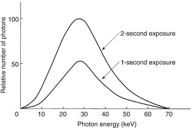
Changing the time controls the duration of the exposure and thus the number of photons generated (Fig. 1-16). When the exposure time is doubled, the number of photons generated at all energies in the x-ray emission spectrum is doubled, but the range of photon energies is unchanged.
TUBE CURRENT (mA)
The quantity of radiation produced by an x-ray tube (i.e., the number of photons that reach the patient and film) is directly proportional to the tube current (mA) and the time the tube is operated (Fig. 1-17). As the mA setting is increased, more power is applied to the filament, which heats up and releases more electrons that collide with the target to produce radiation. The quantity of radiation produced is expressed as the product of time and tube current. The quantity of radiation remains constant regardless of variations in mA and time as long as the product remains constant. For instance, a machine operating at 10 mA for 1 second (10 mA) produces the same quantity of radiation when operated at 20 mA for 0.5 second (10 mA). In practice some dental x-ray machines fall slightly short of this ideal constancy. The term beam quantity or beam intensity refers to the number of photons an x-ray beam.

FIG. 1-17 Spectrum of photon energies showing that as tube current (mA) increases (kVp and exposure time held constant), so does the total number of photons. The mean energy and maximal energies of the beams are unchanged. Compare with Figure 1-16.
TUBE VOLTAGE (kVp)
Increasing the kVp increases the potential difference between the cathode and the anode, thus increasing the energy of each electron when it strikes the target. This results in an increased efficiency of conversion of electron energy into x-ray photons and thus an increase in (1) the number of photons generated, (2) their mean energy, and (3) their maximal energy (Fig. 1-18).

FIG. 1-18 Spectrum of photon energies showing that, as the kVp is increased (tube current and exposure time held constant), there is a corresponding increase in the mean energy of the beam, the total number of photons emitted, and the maximal energy of the photons.
The ability of x-ray photons to penetrate matter depends on their energy. High-energy x-ray photons have a greater probability of penetrating matter, whereas lower-energy photons have a greater probability of being absorbed. Therefore the higher the kVp and mean energy of the x-ray beam, the greater the penetrability of the beam through matter. A useful way to characterize the penetrating quality of an x-ray beam (its energy) is by its half-value layer (HVL). The HVL is the thickness of an absorber, such as aluminum, required to reduce by one half the number of x-ray photons passing through it. As the average energy of an x-ray beam increases, so does its HVL. The term beam quality refers to the mean energy of an x-ray beam.
Exposure time, tube current (mA), and tube voltage are the three variables found on many x-ray machines. In some machines the setting of the tube current, the setting of the tube voltage, or both are fixed. It is recommended that if the tube current is variable that the operator select the highest mA value available and always operate the machine at this setting. This will result in the lowest exposure time for a given exposure and thus minimize the chance of patient movement. Similarly, if tube voltage can be adjusted, it is recommended that the operator select a desired voltage, perhaps 70 kVp, and leave the machine at this setting. This protocol simplifies selecting the proper patient exposure by using just exposure time as the means to adjust for anatomic location within the mouth and patient size.
FILTRATION
Although an x-ray beam consists of a spectrum of x-ray photons of different energies, only photons with sufficient energy to penetrate through anatomic structures and reach the image receptor (film or digital) are useful for diagnostic radiology. Photons that are of such low energy that they cannot reach the receptor contribute to patient exposure (risk) but do not offer any benefit. Consequently, to reduce patient dose, such low-energy photons should be removed from the beam. This can be accomplished, in part, by placing an aluminum filter in the path of the beam. An aluminum filter preferentially removes many of the lower-energy photons with lesser effect on the higher-energy photons that are able to contribute to making an image (Fig. 1-19).
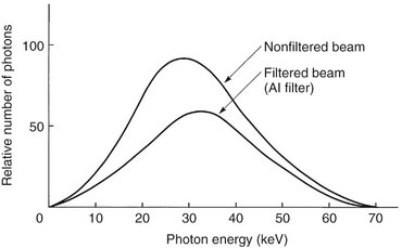
FIG. 1-19 Filtering an x-ray beam with aluminum preferentially removes low-energy photons, thereby reducing the beam intensity while increasing the mean energy of the residual beam.
Inherent filtration consists of the materials that x-ray photons encounter as they travel from the focal spot on the target to form the usable beam outside the tube enclosure. These materials include the glass wall of the x-ray tube, the insulating oil that surrounds many dental tubes, and the barrier material that prevents the oil from escaping through the x-ray port. The inherent filtration of most x-ray machines ranges from the equivalent of 0.5 to 2 mm of aluminum. Total filtration is the sum of the inherent filtration plus any added external filtration supplied in the form of aluminum disks placed over the port in the head of the x-ray machine. Governmental regulations require the total filtration in the path of a dental x-ray beam to be equal to the equivalent of 1.5 mm of aluminum up to 70 kVp and 2.5 mm of aluminum for all higher voltages (see Chapter 3).
COLLIMATION
A collimator is a metallic barrier with an aperture in the middle used to reduce the size of the x-ray beam and thereby the volume of irradiated tissue (Fig. 1-20). Round and rectangular collimators are most frequently used in dentistry. Dental x-ray beams are usually collimated to a circle  inches (7 cm) in diameter. A round collimator (see Fig. 1-20, A) is a thick plate of radiopaque material (usually lead) with a circular opening centered over the port in the x-ray head through which the x-ray beam emerges. Typically, round collimators are built into open-ended aiming cylinders. Rectangular collimators (see Fig. 1-20, B) further limit the size of the beam to just larger than the x-ray film, thereby further reducing patient exposure. Some types of film-holding instruments also provide rectangular collimation of the x-ray beam (see Chapters 3 and 9).
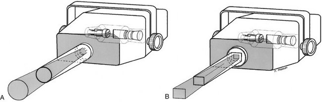
FIG. 1-20 Collimation of an x-ray beam (blue) is achieved by restricting its useful size. A, Circular collimator. B, Rectangular collimator restricts area of exposure to just larger than the detector size.
Use of collimation also improves image quality. When an x-ray beam is directed at a patient, the hard and soft tissues absorb about 90% of the photons and about 10% pass through the patient and reach the film. Many of the absorbed photons generate scattered radiation within the exposed tissues by a process called Compton scattering (see later). These scattered photons travel in all directions, and some reach the film and degrade image quality. Collimating the x-ray beam thus reduces the exposure area and thus the number of scattered photons reaching the film.
INVERSE SQUARE LAW
The intensity of an x-ray beam (the number of photons per cross-sectional area per unit of exposure time) depends on the distance of the measuring device from the focal spot. For a given beam the intensity is inversely proportional to the square of the distance from the source (Fig. 1-21). The reason for this decrease in intensity is that an x-ray beam spreads out as it moves from its source. The relationship is as follows:

where I is intensity and D is distance. Therefore if a dose of 1 Gy is measured at a distance of 2 m, a dose of 4 Gy will be found at 1 m and 0.25 Gy at 4 m.
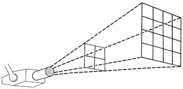
FIG. 1-21 The intensity of an x-ray beam is inversely proportional to the square of the distance between the source and the point of measure.
Therefore changing the distance between the x-ray tube and patient has a marked effect on skin exposure. Such a change requires a corresponding modification of the kVp or mA to keep constant the exposure to the film or digital sensor.
Interactions of X-Rays with Matter
In dental imaging the x-ray beam enters the face of a patient, interacts with hard and soft tissues, and then strikes a digital sensor or film. The incident beam contains photons of many energies but is spatially heterogeneous. That is, the intensity of the beam is essentially uniform from the center of the beam outward. As the beam goes through the patient, it is attenuated, that is, reduced in intensity. This attenuation results from interactions of individual photons in the beam with atoms in the absorber. The x-ray photons are either absorbed or scattered out of the beam. In absorption interactions, photons ionize absorber atoms, convert their energy into kinetic energy of the ejected electron, and cease to exist. In scattering interactions, photons also interact with absorber atoms but then move off in another direction. The frequency of these interactions depends on the type of tissue exposed. Thus although the incident beam striking the patient is spatially homogenous, the remnant beam, the beam that exits the patient, is spatially heterogeneous. It is this differential exposure of the film that allows a radiograph to reveal the morphologic features of enamel, dentin, bone, and soft tissues through which it has passed.
In a dental x-ray beam there are three means of beam attenuation: (1) coherent scattering, (2) photoelectric absorption, and (3) Compton scattering. In addition, about 9% of the primary photons pass through the patient without interaction (Fig. 1-22 and Table 1-2).
TABLE 1-2
Fate of 1,000,000 Incident Photons in Bitewing Projection
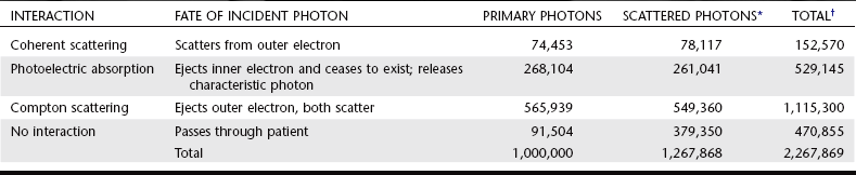
*Scattered photons result from primary, Compton, and coherent interactions.
†Note that the sum of the total number of photoelectric interactions and photons that exit the patient equals the total number of incident photons.
From Gibbs SJ: Personal communication, 1986.
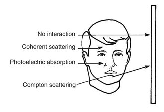
FIG. 1-22 Photons in an x-ray beam interact with the object primarily by Compton scattering, in which case the scattered photon may strike the film and degrade the radiographic image by causing film fog, or photoelectric absorption, in which case they cease to exist. Relatively few photons undergo coherent scattering within the object or pass through the object without interacting and expose the film.
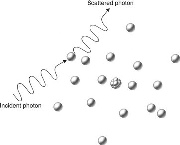
COHERENT SCATTERING
Coherent scattering (also known as classical, elastic, or Thompson scattering) may occur when a low-energy incident photon (less than 10 keV) passes near an outer electron of an atom. The incident photon interacts with the electron by causing it to become momentarily excited at the same frequency as the incoming photon (Fig. 1-23). The incident photon ceases to exist. The excited electron then returns to the ground state and generates another x-ray photon with the same frequency (energy) as in the incident beam. Usually the secondary photon is emitted at an angle to the path of the incident photon. The net effect is that the direction of the incident x-ray photon is altered. Coherent scattering accounts for only about 7% of the total number of interactions in a dental exposure (see Table 1-1). Coherent scattering contributes little to film fog because the number of scattered photons is small and their energy is too low for many of them to reach the film or sensor.
PHOTOELECTRIC ABSORPTION
Photoelectric absorption is critical in diagnostic imaging. This process occurs when an incident photon interacts with an electron in an inner orbital of an atom of the absorbing medium. The photon ejects the electron from its orbital and it becomes a recoil electron (photoelectron) (Fig. 1-24). At this point the incident photon ceases to exist. The kinetic energy imparted to the recoil electron is equal to the energy of the incident photon minus the binding energy of the electron. In the case of atoms with low atomic numbers (e.g., those in most biologic molecules), the binding energy is small and the recoil electron acquires most of the energy of the incident photon. Most photoelectric interactions occur in the 1s orbital because the density of the electron cloud is greatest in this region and thus there is a higher probability of interaction. About 23% of interactions in a dental x-ray beam exposure involve photoelectric absorption.
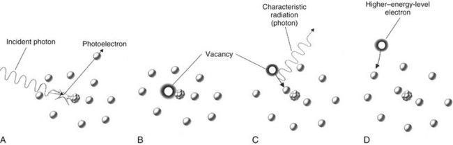
FIG. 1-24 Photoelectric absorption. A, Photoelectric absorption occurs when an incident photon gives up all its energy to an inner electron ejected from the atom (a photoelectron). B, An electron vacancy in the inner orbital results in ionization of the atom. C, An electron from a higher energy level fills the vacancy and emits characteristic radiation. D, All orbitals are subsequently filled, completing the energy exchange.
An atom that has participated in a photoelectric interaction is ionized as a result of the loss of an electron. This electron deficiency (usually in the 1s orbital) is instantly filled, usually by a 2s or 2p orbital electron, with the release of characteristic radiation (see Fig. 1-15). Whatever the orbital of the replacement electron, the characteristic photons generated are of such low energy that they are absorbed within the patient and do not fog the film. Recoil electrons ejected during photoelectric absorption travel only short distances in the absorber before they give up their energy through secondary ionizations.
The clinical significance of photoelectric absorption depends on the fact that the frequency of photoelectric interaction varies directly with the third power of the atomic number of the absorber. For example, because the effective atomic number of compact bone (Z = 13.8) is greater than that of soft tissue (Z = 7.4), the probability that a photon will be absorbed by a photoelectric interaction in bone is approximately 6.5 times (13.83/7.43 = 6.5) greater than in an equal thickness of soft tissue. This difference is readily seen on dental radiographs as a difference in optical density of the image. It is this difference in the absorption that makes the production of a radiographic image possible.
COMPTON SCATTERING
Compton scattering occurs when a photon interacts with an outer orbital electron (Fig. 1-25). About 49% of interactions in a dental x-ray beam exposure involve Compton scattering. In this interaction the incident photon collides with an outer electron, which receives kinetic energy and recoils from the point of impact. The path of the incident photon is deflected by this interaction and is scattered in a new direction from the site of the collision. The energy of the scattered photon equals the energy of the incident photon minus the sum of the kinetic energy gained by the recoil electron and its binding energy. As with photoelectric absorption, Compton scattering results in the loss of an electron and ionization of the absorbing atom. Scattered photons continue on their new paths, causing further ionizations. The recoil electrons also give up their energy by ionizing other atoms.
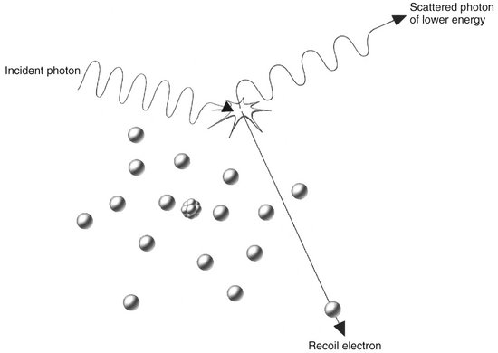
FIG. 1-25 Compton absorption occurs when an incident photon interacts with an outer electron, producing a scattered photon of lower energy than the incident photon and a recoil electron ejected from the target atom.
The probability of a Compton interaction is directly proportional to the electron density of the absorber. The number of electrons in bone (5.55 × 10²³/cc) is greater than in soft tissue (3.34 × 10²³/cc); therefore the probability of Compton scattering is correspondingly greater in bone than in tissue. As a result, Compton interactions contribute to the formation of an image.
Scattered photons travel in all directions. The higher the energy of the incident photon, however, the greater the probability that the angle of scatter of the secondary photon will be small and its direction will be forward. These scattered photons darken and degrade the image while carrying no useful information.
BEAM ATTENUATION
As an x-ray beam travels through matter, its intensity is reduced primarily through photoelectric absorption and Compton scattering. The absorption of the beam depends primarily on the thickness and density of the absorber and the energy of the beam. The reduction of beam intensity is predictable because it depends on physical characteristics of the beam and the absorber. A monochromatic beam of photons, a beam in which all the photons have the same energy, provides a useful example. When only the primary (not scattered) photons are considered, a constant fraction of the beam is attenuated as the beam moves through each unit thickness of an absorber. Therefore 1.5 cm of water may reduce a beam intensity by 50%, the next 1.5 cm by another 50% (to 25% of the original intensity), and so on. This is an exponential pattern of absorption (Fig. 1-26). The HVL described earlier in this chapter is a measure of beam energy describing the amount of an absorber that reduces the beam intensity by half; in the preceding example, the HVL is 1.5 cm of water.
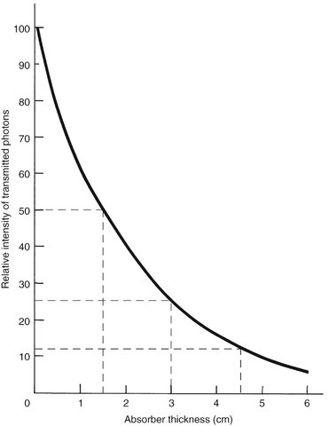
FIG. 1-26 Exponential decay of intensity in a homogeneous photon beam through the absorber, where the HVL is 1.5 cm of absorber. The curve for a heterogeneous x-ray beam does not drop quite as precipitously because of the preferential removal of low-energy photons and the increased mean energy of the resulting beam.
Unlike the previous example, however, there is a wide range of photon energies in an x-ray beam. Low-energy photons are much more likely than high-energy photons to be absorbed. As a consequence, the superficial layers of an absorber tend to remove the low-energy photons and transmit the higher-energy photons. Therefore as an x-ray beam passes through matter, the intensity of the beam decreases, but the mean energy of the residual beam increases by preferential removal of low energy photons. In contrast to the absorption of a monochromatic beam, an x-ray beam is absorbed less and less by each succeeding unit of absorber thickness. For example, the first 1.5 cm of water might absorb 50% of the photons in an incident x-ray beam having a mean energy of 50 kVp. The mean energy of the residual beam might increase 20% as a result of the loss of lower-energy photons. The next 1.5 cm of water removes only about 40% of the photons, and the average energy of the beam increases another 10%. If the water test object is thick enough, the mean energy of the residual beam eventually approaches the peak voltage applied across the tube.
As the energy of an x-ray beam increases, so does the transmission of the beam through an absorber. When the energy of the incident photon is raised to match the binding energy of the 1s orbital electrons of the absorber, however, then the probability of photoelectric absorption increases sharply and the number of transmitted photons is greatly decreased. This is called K-edge absorption. The probability that a photon will interact with an orbital electron is greatest when the energy of the photon equals the binding energy of the electron; it decreases as the photon energy increases. Photons with energy less than the binding energy of 1s orbital electrons interact photoelectrically only with electrons in the 2s or 2p orbitals and in orbitals even farther from the nucleus. Rare earth elements are sometimes used as filters because their 1s orbital binding energies (K edges) (50.24 keV for gadolinium) greatly increase the absorption of high-energy photons. This is desirable because these high-energy photons are not as likely as mid-energy photons to contribute to a radiographic image.
Dosimetry
Determining the quantity of radiation exposure or dose is termed dosimetry. The term dose is used to describe the amount of energy absorbed per unit of mass at a site of interest. Exposure is a measure of radiation on the basis of its ability to produce ionization in air under standard conditions of temperature and pressure (STP).
UNITS OF MEASUREMENT
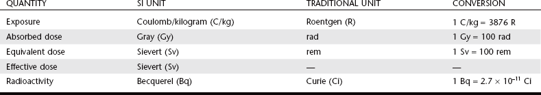
Table 1-3 presents some of the more frequently used units for measuring quantities of radiation. In recent years a move has occurred to use a modernized version of the metric system called the SI system (Système International d’Unités).* This book uses SI units. The SI system uses base units including the kilogram (kg) (mass), the meter (length), the second (time), the ampere (electric current), and the mole (amount of substance). SI-derived units, including newton (force) and joule (energy), evolve from these base units. The following units are SI-derived units with special names.
TABLE 1-3
Summary of Radiation Quantities and Units
Data from The NIST Reference on Constants, Units, and Uncertainty: http://physics.nist.gov/cuu/Units/units.html.
Exposure
Exposure is a measure of radiation quantity, the capacity of radiation to ionize air. The SI unit of exposure is air kerma, an acronym for kinetic energy released in matter. Kerma measures the kinetic energy transferred from photons to electrons and is expressed in units of dose (gray [Gy]), where 1 Gy equals 1 joule/kg. Kerma is the sum of the initial kinetic energies of all the charged particles liberated by uncharged ionizing radiation (neutrons and photons) in a sample of matter, divided by the mass of the sample. It has replaced the roentgen (R), the traditional unit of radiation exposure measured in air.
Absorbed Dose
Absorbed dose is a measure of the energy absorbed by any type of ionizing radiation per unit of mass of any type of matter. The SI unit is the Gy, where 1 Gy equals 1 joule/kg. The traditional unit of absorbed dose is the rad (radiation absorbed dose), where 1 rad is equivalent to 100 ergs per gram (g) of absorber. One gray equals 100 rads.
Equivalent Dose
The equivalent dose (HT) is used to compare the biologic effects of different types of radiation on a tissue or organ. Particulate radiations have a high LET and are more damaging to tissue than is low-LET radiation such as x rays. This relative biologic effectiveness of different types of radiation is called the radiation-weighting factor (WR). For instance, deposition of 1 Gy of high-energy protons causes five times as much damage as 1 Gy of x-ray photons. The WR of photons, the reference, is 1. The WR of 5 keV neutrons and high-energy protons is 5 and the WR of α particles is 20. To account for this difference, the HT is computed as the product of the absorbed dose (DT) averaged over a tissue or organ and the WR:
The unit of equivalent dose is the sievert (Sv). For diagnostic x-ray examinations 1 Sv equals 1 Gy. The traditional unit of equivalent dose is the rem (roentgen equivalent man). One sievert equals 100 rem.
Effective Dose
The effective dose (E) is used to estimate the risk in humans. For exposures to a part of the body, for instance, the jaws, the effective dose measures the equivalent whole-body dose. This allows the risk from exposure to one region of the body to be compared with the risk from exposure to another region. In addition to considering the relative biologic effectiveness of different types of radiation, it also considers the radiosensitivity of different tissues for cancer formation or heritable effect. The comparative radiosensitivities of different tissues are measured by the WT. The tissue-weighting factors include red bone marrow, breast, colon, lung, and stomach, all 0.12; gonads 0.08; bladder, esophagus, liver, and thyroid, all 0.04; bone surface, brain, salivary glands, and skin, all 0.01; and other specified tissues totaling 0.12. Thus E is the sum of the products of the equivalent dose to each organ or tissue (HT) and the tissue-weighting factor (WT):
Radioactivity
The measurement of radioactivity (A) describes the decay rate of a sample of radioactive material. The SI unit is the becquerel (Bq); 1 Bq equals 1 disintegration/second. The traditional unit is the curie (Ci), which corresponds to the activity of 1 g of radium (3.7 × 10¹⁰ disintegrations/second). Accordingly, 1 mCi equals 37 megaBq and 1 Bq equals 2.7 × 10⁻¹¹ Ci.
Bushberg, JT. The essential physics of medical imaging, ed 2. Baltimore: Lippincott Williams & Wilkins; 2001.
Bushong, SC. Radiologic science for technologists: physics, biology, and protection, ed 7. St Louis: Mosby; 2001.
Greene, B. The elegant universe, ed 1. Vintage; 1999.
International Commission on Radiological Protection, Radiation protection: radiological protection and safety in medicine. ICRP Publication No. 73. Elsevier Science; 1996.
Sacks, O. Uncle Tungsten: memories of a chemical boyhood. Vintage; 2002.
Wolbarst, AB. Physics of radiology, ed 2. Madison, Wis: Medical Physics; 2005.
*The NIST Reference on Constants, Units, and Uncertainty: http://physics.nist.gov/cuu/Units/units.html.