Normal Radiographic Anatomy
The radiographic recognition of disease requires a sound knowledge of the radiographic appearance of normal structures. Intelligent diagnosis mandates an appreciation of the wide range of variation in the appearance of normal anatomic structures. Similarly, most patients demonstrate many of the normal radiographic landmarks, but it is a rare patient who shows them all. Accordingly, the absence of one or even several such landmarks in any individual should not necessarily be considered abnormal.
Teeth
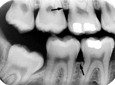
Teeth are composed primarily of dentin, with an enamel cap over the coronal portion and a thin layer of cementum over the root surface (Fig. 10-1). The enamel cap characteristically appears more radiopaque than the other tissues because it is the most dense, naturally occurring substance in the body. Because it is 90% mineral, it causes the greatest attenuation of x-ray photons. Its radiographic appearance is uniformly opaque and without evidence of the fine structure. Only the occlusal surface reflects the complex gross anatomy. The dentin is about 75% mineralized, and because of its lower mineral content, its radiographic appearance is roughly comparable to that of bone. Dentin is smooth and homogeneous on radiographs because of its uniform morphologic features. The junction between enamel and dentin appears as a distinct interface that separates these two structures. The thin layer of cementum on the root surface has a mineral content (50%) comparable to that of dentin. Cementum is not usually apparent radiographically because the contrast between it and dentin is so low and the cementum layer is so thin.
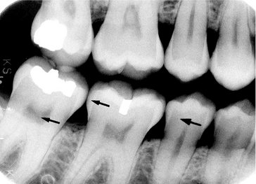
FIG. 10-1 Teeth are composed of pulp (arrow on the second molar), enamel (arrow on the first molar), dentin (arrow on the second premolar), and cementum (usually not visible radiographically).
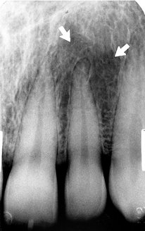
Diffuse radiolucent areas with ill-defined borders may be apparent radiographically on the mesial or distal aspects of teeth in the cervical regions between the edge of the enamel cap and the crest of the alveolar ridge (Fig. 10-2). This phenomenon, called cervical burnout, is caused by the normal configuration of the affected teeth, which results in decreased x-ray absorption in the areas in question. Close inspection will reveal intact edges of the proximal surfaces. Furthermore, the perception of these radiolucent areas results from the contrast with the adjacent, relatively opaque enamel and alveolar bone. Such radiolucencies should be anticipated in almost all teeth and should not be confused with root surface caries, which frequently have a similar appearance.
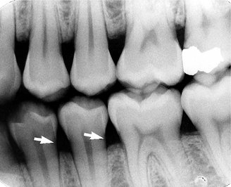
FIG. 10-2 Cervical burnout caused by overexposure of the lateral portion of teeth between the enamel and alveolar crest (arrows).
The pulp of normal teeth is composed of soft tissue and consequently appears radiolucent. The chambers and root canals containing the pulp extend from the interior of the crown to the apices of the roots. Although the shape of most pulp chambers is fairly uniform within tooth groups, great variations exist among individuals in the size of the pulp chambers and the extent of pulp horns. The practitioner must anticipate such variations in the proportions and distribution of the pulp and verify them radiographically when planning restorative procedures.
In normal, fully formed teeth the root canal may be apparent, extending from the pulp chamber to the apex of the root. An apical foramen is usually recognizable (Fig. 10-3). In other normal teeth the canal may appear constricted in the region of the apex and not discernible in the last millimeter or so of its length (Fig. 10-4). In this case the canal may occasionally exit on the side of the tooth, just short of the radiographic apex. Lateral canals may occur as branches of an otherwise normal root canal. They may extend to the apex and end in a normal, discernible foramen or may exit the side of the root. In either case, two or more terminal foramina might cause endodontic treatment to fail if they are not identified.
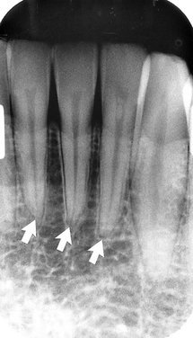
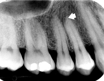
FIG. 10-4 Although the root canal is not radiographically visible in the apical 2 mm of a tooth, anatomically it is present (arrow).
At the end of a developing tooth root the pulp canal diverges and the walls of the root rapidly taper to a knife edge (Fig. 10-5). In the recess formed by the root walls and extending a short distance beyond is a small, rounded, radiolucent area in the trabecular bone, surrounded by a thin layer of hyperostotic bone. This is the dental papilla bounded by its bony crypt. The papilla forms the dentin and the primordium of the pulp. When the tooth reaches maturity, the pulpal walls in the apical region begin to constrict and finally come into close apposition. Awareness of this sequence and its radiographic pattern is often useful in evaluating the stage of maturation of the developing tooth; it also helps avoid misidentifying the apical radiolucency as a periapical lesion.
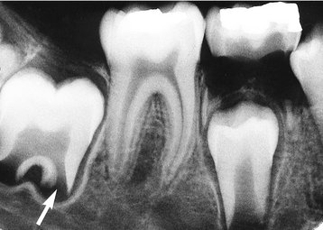
FIG. 10-5 A developing root shown by a divergent apex around the dental papilla (arrow), which is enclosed by an opaque bony crypt.
In a mature tooth, the shape of the pulp chamber and canal may change. With aging occurs a gradual deposition of secondary dentin. This process begins apically, proceeds coronally, and may lead to pulp obliteration. Trauma to the tooth (e.g., from caries, a blow, restorations, attrition, or erosion) also may stimulate dentin production, leading to a reduction in size of the pulp chamber and canals. Such cases usually include evidence of the source of the pathologic stimulus. In the case of a blow to the teeth, however, only the patient’s recollection may suggest the true reason for the reduced pulp chamber size.
Supporting Structures
A radiograph of sound teeth in a normal dental arch demonstrates that the tooth sockets are bounded by a thin radiopaque layer of dense bone (Fig. 10-6). Its name, lamina dura (“hard layer”), is derived from its radiographic appearance. This layer is continuous with the shadow of the cortical bone at the alveolar crest. It is only slightly thicker and no more highly mineralized than the trabeculae of cancellous bone in the area. Its radiographic appearance is caused by the fact that the x-ray beam passes tangentially through many times the thickness of the thin bony wall, which results in its observed attenuation (the egg-shell effect). Developmentally the lamina dura is an extension of the lining of the bony crypt that surrounds each tooth during development.
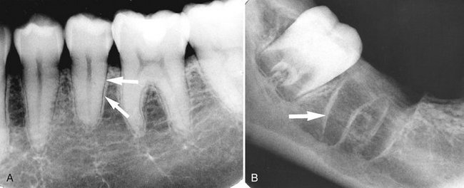
FIG. 10-6 The lamina dura (arrows) appears as a thin opaque layer of bone around teeth, A, and around a recent extraction socket, B.
The appearance of the lamina dura on radiographs may vary. When the x-ray beam is directed through a relatively long expanse of the structure, the lamina dura appears radiopaque and well defined. When the beam is directed more obliquely, however, the lamina dura appears more diffuse and may not be discernible. In fact, even if the supporting bone in a healthy arch is intact, identification of a lamina dura completely surrounding every root on each film is frequently difficult, although it usually is evident to some extent about the roots on each film (Fig. 10-7). In addition, small variations and disruptions in the continuity of the lamina dura may result from superimpositions of cancellous bone and small nutrient canals passing from the marrow spaces to the periodontal ligament.
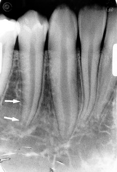
FIG. 10-7 The lamina dura is poorly visualized on the distal surface of this premolar (arrows) but is clearly seen on the mesial surface.
The thickness and density of the lamina dura on the radiograph vary with the amount of occlusal stress to which the tooth is subjected. The lamina dura is wider and more dense around the roots of teeth in heavy occlusion and thinner and less dense around teeth not subjected to occlusal function.
The image of a double lamina dura is not uncommon if the mesial or distal surfaces of roots present two elevations in the path of the x-ray beam. A common example of this is seen on the buccal and lingual eminences on the mesial surface of mandibular first molar roots (Fig. 10-8).
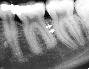
FIG. 10-8 A double periodontal ligament space and lamina dura (arrows) may be seen when there is a convexity of the proximal surface of the root.
The appearance of the lamina dura is a valuable diagnostic feature. The presence of an intact lamina dura around the apex of a tooth strongly suggests a vital pulp. Because of the variable appearance of the lamina dura, however, the absence of its image around an apex on a radiograph may be normal. Rarely, in the absence of disease the lamina dura may be absent from a molar root extending into the maxillary sinus. The clinician is therefore advised to consider other signs and symptoms, as well as the integrity of the lamina dura, when establishing a diagnosis and treatment.
ALVEOLAR CREST
The gingival margin of the alveolar process that extends between the teeth is apparent on radiographs as a radiopaque line, the alveolar crest (Fig. 10-9). The level of this bony crest is considered normal when it is not more than 1.5 mm from the cementoenamel junction of the adjacent teeth. The alveolar crest may recede apically with age and show marked resorption with periodontal disease. Radiographs can demonstrate only the position of the crest; determining the significance of its level is primarily a clinical problem (see Chapter 18).
The length of the normal alveolar crest in a particular region depends on the distance between the teeth in question. In the anterior region the crest is reduced to only a point of bone between the close-set incisors. Posteriorly it is flat, aligned parallel with and slightly below a line connecting the cementoenamel junctions of the adjacent teeth. The crest of the bone is continuous with the lamina dura and forms a sharp angle with it. Rounding of these sharp junctions is indicative of periodontal disease.
The image of the crest varies from a dense layer of cortical bone to a smooth surface without cortical bone. In the latter case the trabeculae at the surface are of normal size and density. In the posterior regions this range of radiodensity of the crest is presumed to be normal if the bone is at a proper level in relation to the teeth. The absence of an image of cortex between the incisors, however, is considered by many to be an indication of incipient disease, even if the level of the bone is not abnormal.
PERIODONTAL LIGAMENT SPACE
Because the periodontal ligament (PDL) is composed primarily of collagen, it appears as a radiolucent space between the tooth root and the lamina dura. This space begins at the alveolar crest, extends around the portions of the tooth roots within the alveolus, and returns to the alveolar crest on the opposite side of the tooth (Fig. 10-10).
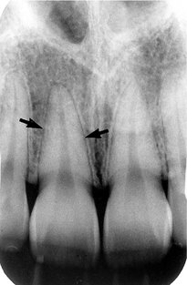
FIG. 10-10 The periodontal ligament space (arrows) is seen as a narrow radiolucency between the tooth root and lamina dura.
The PDL varies in width from patient to patient, from tooth to tooth in the individual, and even from location to location around one tooth (Fig. 10-11). Usually it is thinner in the middle of the root and slightly wider near the alveolar crest and root apex, suggesting that the fulcrum of physiologic movement is in the region where the PDL is thinnest. The thickness of the ligament relates to the degree of function because the PDL is thinnest around the roots of embedded teeth and those that have lost their antagonists. The reverse is not necessarily true, however, because an appreciably wider space is not regularly observed in persons with especially heavy occlusion or bruxism.
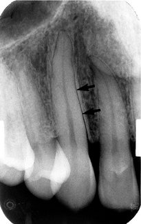
FIG. 10-11 The periodontal ligament space appears wide on the mesial surface of this canine (arrows) and thin on the distal surface.
The shape of the tooth creates the appearance of a double PDL space. When the x-ray beam is directed so that two convexities of a root surface appear on a film, the double PDL space is seen (see Fig. 10-8).
CANCELLOUS BONE
The cancellous bone (also called trabecular bone or spongiosa) lies between the cortical plates in both jaws. It is composed of thin radiopaque plates and rods (trabeculae) surrounding many small radiolucent pockets of marrow. The radiographic pattern of the trabeculae comes from two anatomic sources. First is the cancellous bone itself. The second is the endosteal surface of the outer cortical bone where the cancellous bone fuses with the cortical bone. At this surface trabecular plates are relatively thick and make a significant contribution to the radiographic image. The trabecular pattern shows considerable intrapatient and interpatient variability, which is normal and not a manifestation of disease. To evaluate the trabecular pattern in a specific area, the practitioner should examine the trabecular distribution, size, and density and compare them throughout both jaws, and especially to the corresponding region on the opposite side. This frequently demonstrates that a particularly suspect region is characteristic for the individual.
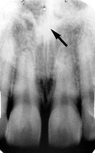
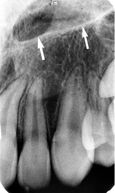
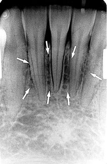
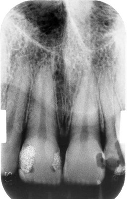
The trabeculae in the anterior maxilla are typically thin and numerous, forming a fine, granular, dense pattern (Fig. 10-12), and the marrow spaces are consequently small and relatively numerous. In the posterior maxilla the trabecular pattern is usually quite similar to that in the anterior maxilla, although the marrow spaces may be slightly larger.
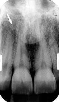
FIG. 10-12 The trabecular pattern in the anterior maxilla is characterized by fine trabecular plates and multiple small trabecular spaces (arrow).
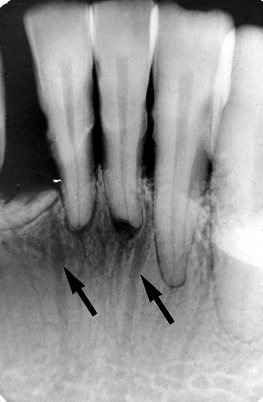
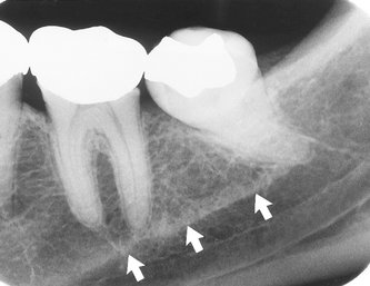
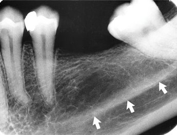
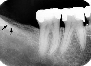
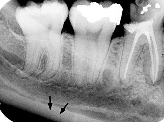
In the anterior mandible the trabeculae are somewhat thicker than in the maxilla, resulting in a coarser pattern (Fig. 10-13) with trabecular plates that are oriented more horizontally. The trabecular plates are also fewer than in the maxilla, and the marrow spaces are correspondingly larger. In the posterior mandible the periradicular trabeculae and marrow spaces may be comparable to those in the anterior mandible but are usually somewhat larger (Fig. 10-14). The trabecular plates are oriented mainly horizontally in this region also. Below the apices of the mandibular molars the number of trabeculae dwindles still more. In some cases the area from just below the molar roots to the inferior border of the mandible may appear to be almost devoid of trabeculae. The distribution and size of the trabeculae throughout both jaws show a relationship to the thickness (and strength) of the adjacent cortical plates. It may be speculated that where the cortical plates are thick (e.g., in the posterior region of the mandibular body) internal bracing by the trabeculae is not required, so there are relatively few except where required to support the alveoli. By contrast, in the maxilla and anterior region of the mandible, where the cortical plates are relatively thin and less rigid, trabeculae are more numerous and lend internal bolstering to the jaw. Occasionally the trabecular spaces in this region are very irregular, with some so large that they mimic pathologic lesions.
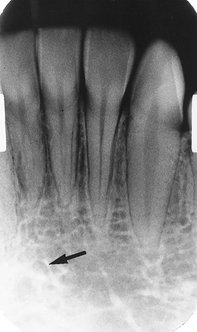
FIG. 10-13 The trabecular pattern in the anterior mandible is characterized by coarser trabecular plates and larger marrow spaces (arrow) than in the anterior maxilla.
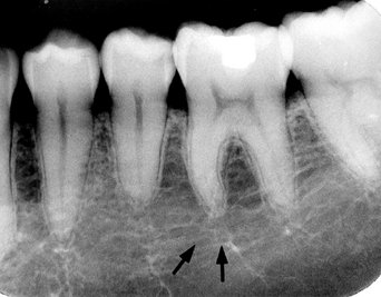
FIG. 10-14 The trabecular pattern in the posterior mandible is quite variable, generally showing large marrow spaces and sparse trabeculation, especially inferiorly (arrows).
If trabeculae are apparently absent, suggesting the presence of disease, it is often revealing to examine previous radiographs of the region in question. This helps determine whether the current appearance represents a change from a prior condition. An abnormality is more likely when the comparison indicates a change in the trabecular pattern. If prior films are not available, it is frequently useful to repeat the radiographic examination at a reduced exposure because this often demonstrates the presence of an expected but sparse trabecular pattern that was overexposed and burned out in the initial projection. Finally, if prior films are not available and reduced exposure does not allay the examiner’s apprehension, it may be appropriate to expose another radiograph at a later time to monitor for ominous changes. Again, considerable variation may exist in trabecular pattern among patients, so examining all regions of the jaws is important in evaluating a trabecular pattern for any individual. This enables the dentist to determine the general nature of the particular pattern and whether any areas deviate appreciably from that norm.
The buccal and lingual cortical plates of the mandible and maxilla do not cast a discernible image on periapical radiographs.
MAXILLA
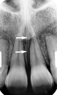
The intermaxillary suture (also called the median suture) appears on intraoral periapical radiographs as a thin radiolucent line in the midline between the two portions of the premaxilla (Fig. 10-15). It extends from the alveolar crest between the central incisors superiorly through the anterior nasal spine and continues posteriorly between the maxillary palatine processes to the posterior aspect of the hard palate. It is not unusual for this narrow radiolucent suture to terminate at the alveolar crest in a small rounded or V-shaped enlargement (Fig. 10-16). The suture is limited by two parallel radiopaque borders of thin cortical bone on each side of the maxilla. The radiolucent region is usually of uniform width. The adjacent cortical margins may be either smooth or slightly irregular. The appearance of the intermaxillary suture depends on both anatomic variability and the angulation of the x-ray beam through the suture.
Anterior Nasal Spine
The anterior nasal spine is most frequently demonstrated on periapical radiographs of the maxillary central incisors (Fig. 10-17). Located in the midline, it lies some 1.5 to 2 cm above the alveolar crest, usually at or just below the junction of the inferior end of the nasal septum and the inferior outline of the nasal aperture. It is radiopaque because of its bony composition and it is usually V shaped.
Nasal Aperture
Because the air-filled nasal aperture (and cavity) lies just above the oral cavity, its radiolucent image may be apparent on intraoral radiographs of the maxillary teeth, especially in central incisor projections. On periapical radiographs of the incisors the inferior border of the fossa aperture as a radiopaque line extending bilaterally away from the base of the anterior nasal spine (Fig. 10-18). Above this line is the radiolucent space of the inferior portion of the cavity. If the radiograph was made with the x-ray beam directed in the sagittal plane, the relatively radiopaque nasal septum is seen arising in the midline from the anterior nasal spine (Fig. 10-19). The shadow of the septum may appear wider than anticipated and not sharply defined because the image is a superimposition of septal cartilage and vomer bone. Also, the septum frequently deviates slightly from the midline, and its plate of bone (the vomer) is somewhat curved.

FIG. 10-18 The anterior floor of the nasal aperture (arrows) appears as opaque lines extending laterally from the anterior nasal spine.
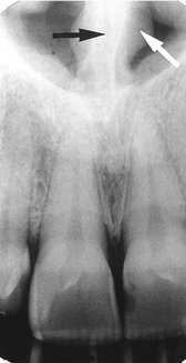
FIG. 10-19 The nasal septum (black arrow) arises directly above the anterior nasal spine and is covered on each side by nasal mucosa (white arrow).
The nasal cavity contains the opaque shadows of the inferior conchae extending from the right and left lateral walls for varying distances toward the septum. These conchae fill varying amounts of the lateral portions of the cavity (Fig. 10-20). The floor of the nasal aperture and a small segment of the nasal cavity are occasionally projected high onto a maxillary canine radiograph (Fig. 10-21). Also, in the posterior maxillary region, the floor of the nasal cavity may be seen in the region of the maxillary sinus. (It is not possible from a single radiograph to determine which of two superimposed structures is in front of or behind the other unless the conclusion is based on an awareness of the anatomic features and relationships.) It may falsely convey the impression of a septum in the sinus or a limiting superior sinus wall (Fig. 10-22).
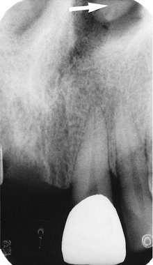
FIG. 10-20 The mucosal covering of the inferior concha (arrow) is occasionally visualized in the nasal cavity.
Incisive Foramen
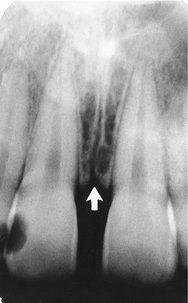
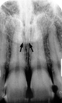
The incisive foramen (also called the nasopalatine or anterior palatine foramen) in the maxilla is the oral terminus of the nasopalatine canal. This canal originates in the anterior floor of the nasal fossa. The incisive foramen transmits the nasopalatine vessels and nerves (which may participate in the innervation of the maxillary central incisors) and lies in the midline of the palate behind the central incisors at approximately the junction of the median palatine and incisive sutures. Its radiographic image is usually projected between the roots and in the region of the middle and apical thirds of the central incisors (Fig. 10-23). The foramen varies markedly in its radiographic shape, size, and sharpness. It may appear smoothly symmetric, with numerous forms, or very irregular, with a well-demarcated or ill-defined border. The position of the foramen is also variable and may be recognized at the apices of the central incisor roots, near the alveolar crest, anywhere in between, or extending over the entire distance. The great variability of its radiographic image is primarily the result of (1) the differing angles at which the x-ray beam is directed for the maxillary central incisors and (2) some variability in its anatomic size.
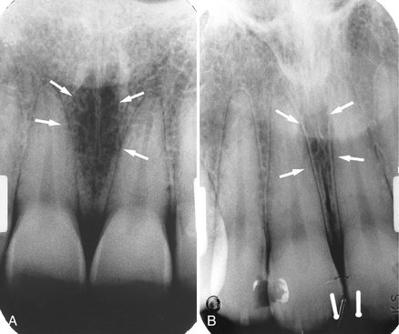
FIG. 10-23 A, The incisive foramen appears as an ovoid radiolucency (arrows) between the roots of the central incisors. B, Note its borders, which are diffuse but within normal limits.
Familiarity with the incisive foramen is important because it is a potential site of cyst formation. An incisive canal cyst is radiographically discernible because it frequently causes a readily perceived enlargement of the foramen and canal. The presence of a cyst is presumed if the width of the foramen exceeds 1 cm or if enlargement can be demonstrated on successive radiographs. Also, if the radiolucency of the normal foramen is projected over the apex of one central incisor, it may suggest a pathologic periapical condition. The absence of disease is indicated by a lack of clinical symptoms and an intact lamina dura around the central incisor in question.
The lateral walls of the nasopalatine canal are not usually seen on periapical views but on occasion can be visualized on a projection of the central incisors as a pair of radiopaque lines running vertically from the superior foramina of the nasopalatine canal to the incisive foramen (Fig. 10-24, A). Cone-beam images of this region, however, regularly demonstrate the borders of the nasopalatine canal (Figs. 10-24, B and C). Visualization of these structures is important when placing an implant in this region is considered.
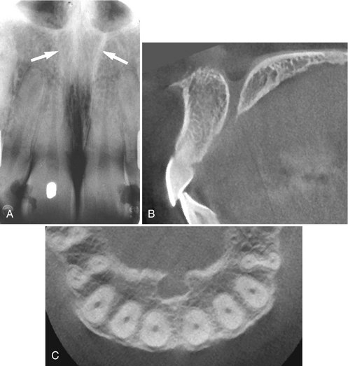
FIG. 10-24 Nasopalatine canal.
A, The lateral walls of the nasopalatine canal (arrows) extend from the incisive foramen to the floor of the nasal fossa. B, Cone-beam image in the sagittal plane demonstrates superior foramina in the floor of the nasal fossa, the anterior and posterior borders of the canal, and the incisive foramen opening onto the hard palate. C, Cone-beam image in the axial plane at the level of the incisive foramen demonstrates anterior and lateral borders of the incisive canal lying palatal to the incisor roots seen in cross section. (B and C made with 3DX Accuitomo, J. Morita.)
Superior Foramina of the Nasopalatine Canal
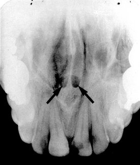
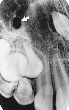
The nasopalatine canal originates at two foramina in the floor of the nasal cavity. The openings are on each side of the nasal septum, close to the anteroinferior border of the nasal cavity, and each canal passes downward somewhat anteriorly and medially to unite with the canal from the other side in a common opening, the incisive (nasopalatine) foramen. The superior foramina of the canal occasionally appear in projections of the maxillary incisors, especially when an exaggerated vertical angle is used (Fig. 10-25). They are usually round or oval, although they make take a variety of outlines, depending on the angle of projection.
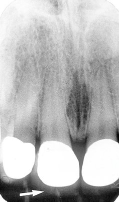
Lateral Fossa
The lateral fossa (also called incisive fossa) is a gentle depression in the maxilla near the apex of the lateral incisor (Fig. 10-26). On periapical projections of this region it may appear diffusely radiolucent. The image will not be misinterpreted as a pathologic condition, however, if the radiograph is examined for an intact lamina dura around the root of the lateral incisor. This finding, coupled with absence of clinical symptoms, suggests normalcy of the bone.
Nose
The soft tissue of the tip of the nose is frequently seen in projections of the maxillary central and lateral incisors, superimposed over the roots of these teeth. The image of the nose has a uniform, slightly opaque appearance with a sharp border (Fig. 10-27). Occasionally the radiolucent nares can be identified, especially when a steep vertical angle is used.
Nasolacrimal Canal
The nasal and maxillary bones form the nasolacrimal canal. It runs from the medial aspect of the anteroinferior border of the orbit inferiorly to drain under the inferior concha into the nasal cavity. Occasionally it can be visualized on periapical radiographs in the region above the apex of the canine, especially when steep vertical angulation is used (Fig. 10-28). The nasolacrimal canals are routinely seen on maxillary occlusal projections (see Chapter 9) in the region of the molars (Fig. 10-29).
Maxillary Sinus
The maxillary sinus, like the other paranasal sinuses, is an air-containing cavity lined with mucous membrane. It develops by the invagination of mucous membrane from the nasal cavity. The largest of the paranasal sinuses, it normally occupies virtually the entire body of the maxilla. Its function is unknown.
The sinus may be considered as a three-sided pyramid, with its base the medial wall adjacent to the nasal cavity and its apex extending laterally into the zygomatic process of the maxilla. Its three sides are (1) the superior wall forming the floor of the orbit, (2) the anterior wall extending above the premolars, and (3) the posterior wall bulging above the molar teeth and maxillary tuberosity. The sinus communicates with the nasal cavity by the ostium, some 3 to 6 mm in diameter positioned and under the posterior aspect of the middle concha of the ethmoid bone.
The borders of the maxillary sinus appear on periapical radiographs as a thin, delicate, tenuous radiopaque line (actually a thin layer of cortical bone) (Fig. 10-30). In the absence of disease it appears continuous, but on close examination it can be seen to have small interruptions in its smoothness or density. These discontinuities are probably illusions caused by superimposition of small marrow spaces. In adults the sinuses are usually seen to extend from the distal aspect of the canine to the posterior wall of the maxilla above the tuberosity.
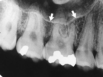
FIG. 10-30 The inferior border of the maxillary sinus (arrows) appears as a thin radiopaque line near the apices of the maxillary premolars and molars.
The maxillary sinuses show considerable variation in size. They enlarge during childhood, achieving mature size by the age of 15 to 18 years. They may change during adult life in response to environmental factors. The right and left sinuses usually appear similar in shape and size, although marked asymmetry is occasionally present. The floors of the maxillary sinus and nasal cavity are seen on dental radiographs at approximately the same level around the age of puberty. In older individuals the sinus may extend farther into the alveolar process, and in the posterior region of the maxilla its floor may appear considerably below the level of the floor of the nasal cavity. Anteriorly each sinus is restricted by the canine fossa and is usually seen to sweep superiorly, crossing the level of the floor of the nasal cavity in the premolar or canine region. Consequently, on periapical radiographs of the canine, the floors of the sinus and nasal cavity are often superimposed and may be seen crossing one another, forming an inverted Y in the area (Fig. 10-31).
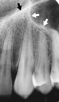
FIG. 10-31 The anterior border of the maxillary sinus (white arrows) crosses the floor of the nasal fossa (black arrow).
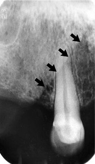
The outline of the nasal fossa is usually heavier and more diffuse than that of the thin, delicate cortical bone denoting the sinus. The degree of extension of the maxillary sinus into the alveolar process is extremely variable. In some projections the floor of the sinus will be well above the apices of the posterior teeth; in others it may extend well beyond the apices toward the alveolar ridge. In response to a loss of function (associated with the loss of posterior teeth) the sinus may expand farther into the alveolar bone, occasionally extending to the alveolar ridge (Fig. 10-32).
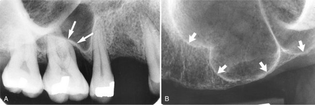
FIG. 10-32 The floor of the maxillary sinus (arrows) extends toward the crest of the alveolar ridge in response to missing teeth.
The roots of the molars usually lie in close apposition to the maxillary sinus. Root apices may project anatomically into the floor of the sinus, causing small elevations or prominences. The thin layer of bone covering the root is seen as a fusion of the lamina dura and the floor of the sinus. Rarely, defects may be present in the bony covering of the root apices in the sinus floor, and a periapical radiograph will fail to show lamina dura covering the apex.
When the rounded sinus floor dips between the buccal and palatal molar roots and is medial to the premolar roots, the projection of the apices is superior to the floor. This appearance conveys the impression that the roots project into the sinus cavity, which is an illusion. As the positive vertical angle of the projection is increased, the roots medial to the sinus appear to project farther into the sinus cavity. In contrast, the roots that are lateral to the sinus appear to move either out of the sinus or farther away from it as the angle is increased.
The intimate relationship between sinus and teeth leads to the possibility that clinical symptoms originating in the sinus may be perceived in the teeth and vice versa. This proximity of sinus and teeth is in part a consequence of the gradual developmental expansion of the maxillary sinus, which thins the sinus walls and opens the canals that traverse the anterolateral and posterolateral walls and carry the superior alveolar nerves. The nerves are then in intimate contact with the membrane lining the sinus. As a result, an acute inflammation of the sinus is frequently accompanied by pain in the maxillary teeth innervated by that portion of the nerve proximal to the insult. Subjective symptoms in the area of the maxillary posterior teeth may require careful analysis to differentiate tooth pain from sinus pain.
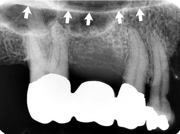
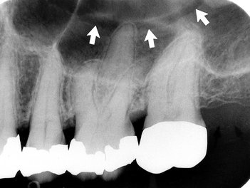
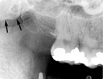
Frequently, thin radiolucent lines of uniform width are found within the image of the maxillary sinus (Fig. 10-33). These are the shadows of neurovascular canals or grooves in the lateral sinus walls that accommodate the posterior superior alveolar vessels, their branches, and the accompanying superior alveolar nerves. Although they may be found coursing in any direction (including vertically), they are usually seen running a curved posteroanterior course that is convex toward the alveolar process. On occasion they may be found to branch and rarely also to extend outside the image of the sinus and continue as an interradicular channel. Because such vascular markings are not seen in the walls of cysts, they may serve to distinguish a healthy sinus from a cyst.
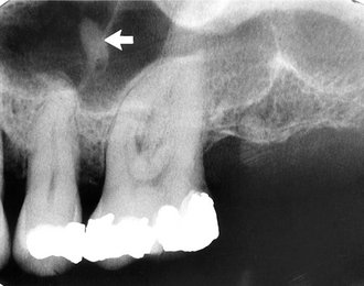
Often one or several radiopaque lines traverse the image of the maxillary sinus (Fig. 10-34). These opaque lines are called septa. They are thin folds of cortical bone that projecting a few millimeters away from the floor and wall of the antrum or they may extend across the sinus. They are usually oriented vertically vary in number, thickness, and length. They appear on many periapical intraoral radiographs and frequently on cone-beam images. Although septa appear to separate the sinuses into distinct compartments, this is seldom the case. Rather, the septa typically extend only a few millimeters into the central volume of the sinus. Septa deserve attention because they sometimes mimic periapical disease, and the chambers they create in the alveolar recess may complicate the search for a root fragment displaced into the sinus.
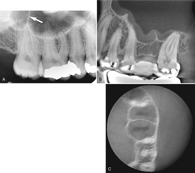
FIG. 10-34 Maxillary Sinus Septa.
A, Septum (arrow) in the maxillary sinus formed by a low ridge of bone on the sinus wall. (See also Fig. 10-32, B). B, Septa in region of missing first molar. Note also thickening of sinus mucous membrane. C, Cross section of B at level of septum showing extension of septa from buccal to palatal wall of sinus. (B and C made with 3DX Accuitomo, J. Morita.)
The floor of the maxillary sinus occasionally shows small radiopaque projections, which are nodules of bone (Fig. 10-35). These must be differentiated from root tips, which they resemble in shape. In contrast to a root fragment, which is quite homogeneous in appearance, the bony nodules often show trabeculation; and although they may be quite well defined, at certain points on their surface they blend with the trabecular pattern of adjacent bone. A root fragment may also be recognized by the presence of a root canal. It is not uncommon to see the floor of the nasal fossa in periapical views of the posterior teeth superimposed on the maxillary sinus (see Fig. 10-22). The floor of the nasal fossa is usually oriented more or less horizontally, depending on film placement, and is superimposed high on maxillary views. The image, a solid opaque line, frequently appears somewhat thicker than the adjacent sinus walls and septa.
Zygomatic Process and Zygomatic Bone
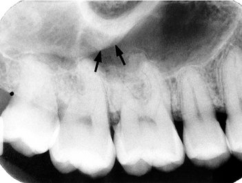
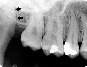
The zygomatic process of the maxilla is an extension of the lateral maxillary surface that arises in the region of the apices of the first and second molars and serves as the articulation for the zygomatic bone. On periapical radiographs the zygomatic process appears as a U-shaped radiopaque line with its open end directed superiorly. The enclosed rounded end is projected in the apical region of the first and second molars (Fig. 10-36). The size, width, and definition of the zygomatic process are quite variable, and its image may be large, depending on the angle at which the beam was projected. The maxillary antrum may expand laterally into the zygomatic process of the maxilla (and even into the zygomatic bone after the maxillozygomatic suture has fused), thereby resulting in a relatively increased radiolucent region within the U-shaped image of the process.
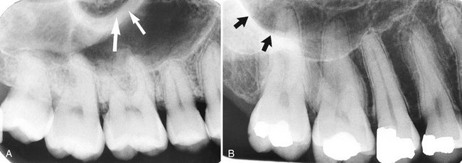
FIG. 10-36 The zygomatic process of the maxilla (arrows) protrudes laterally from the maxillary wall. Its size may be quite variable: small with thick borders (A) or large with thin borders (B).
When the sinus is recessed deep within the process (and perhaps into the zygomatic bone), the image of the air space within the process is dark, and typically, the walls of the process are rather thin and well defined (in contrast to the very dark radiolucent air space). When the sinus exhibits relatively little penetration of the maxillary process (usually in younger individuals or those who have maintained their posterior teeth and vigorous masticatory function), the image of the walls of the zygomatic process tends to be somewhat thicker, and the appearance of the sinus in this region is somewhat smaller and more opaque.
The inferior portion of the zygomatic bone may be seen extending posteriorly from the inferior border of the zygomatic process of the maxilla (thereby completing the zygomatic arch between the zygomatic processes of the maxillary and temporal bones). It can be identified as a uniform gray or white radiopacity over the apices of the molars (Fig. 10-37). The prominence of the molar apices superimposed on the shadow of the zygomatic bone, and the amount of detail supplied by the radiograph, depends in part on the degree of aeration (pneumatization) of the zygomatic bone that has occurred, on the bony structure, and on the orientation of the x-ray beam.
Nasolabial Fold
An oblique line demarcating a region that appears to be covered by a veil of slight radiopacity frequently traverses periapical radiographs of the premolar region (Fig. 10-38). The line of contrast is sharp, and the area of increased radiopacity is posterior to the line. The line is the nasolabial fold, and the opaque veil is the thick cheek tissue superimposed on the teeth and the alveolar process. The image of the fold becomes more evident with age as the repeated creasing of the skin along the line (where the elevator of the lip, zygomatic head, and orbicularis all insert into the skin) and the degeneration of the elastic fibers finally lead to the formation and deepening of permanent folds. This radiographic feature frequently proves useful in identifying the side of the maxilla represented by a film of the area if it is edentulous and few other anatomic features are demonstrated.
Pterygoid Plates
The medial and lateral pterygoid plates lie immediately posterior to the tuberosity of the maxilla. The image of these two plates is extremely variable, and on many intraoral radiographs of the third molar area they do not appear at all. When they are apparent, they almost always cast a single radiopaque homogeneous shadow without any evidence of trabeculation (Fig. 10-39). Extending inferiorly from the medial pterygoid plate is the hamular process (Fig. 10-40), which on close inspection can show trabeculae.
MANDIBLE
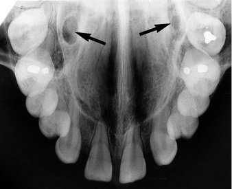
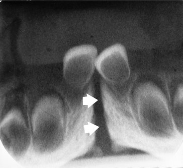
Radiographs of the region of the mandibular symphysis in infants demonstrate a radiolucent line through the midline of the jaw between the images of the forming deciduous central incisors (Fig. 10-41). This suture usually fuses by the end of the first year of life, after which it is no longer radiographically apparent. It is not frequently encountered on dental radiographs because few young patients have cause to be examined radiographically. If this radiolucency is found in older individuals, it is abnormal and may suggest a fracture or a cleft.
Genial Tubercles
The genial tubercles (also called the mental spine) are located on the lingual surface of the mandible slightly above the inferior border and in the midline. They are bony protuberances, more or less spine shaped, that often are divided into a right and left prominence and a superior and inferior prominence. They serve to attach the genioglossus muscles (at the superior tubercles) and the geniohyoid muscles (at the inferior tubercles) to the mandible. They are well visualized on mandibular occlusal radiographs as one or more small projections (Fig. 10-42). Their appearance on periapical radiographs of the mandibular incisor region is variable: often they appear as a radiopaque mass (up to 3 to 4 mm in diameter) in the midline below the incisor roots (Fig. 10-43). They also may not be apparent at all.
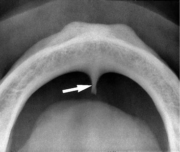
Lingual Foramen
There is usually a foramen on the lingual surface of the midline of the mandible in the region of the genial tubercles, the lingual foramen. Often there are two or even more such foramina. The superior foramen contains a neurovascular bundle from the lingual arteries and nerve, whereas the inferior foramen is supplied from the sublingual or submental arteries and from the mylohyoid nerve. The lingual foramen (Fig. 10-44) is typically visualized as a single round radiolucent canal with a well-defined opaque border lying in the midline below the level of the apices of the incisors.
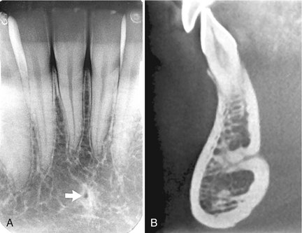
FIG. 10-44 Lingual foramen.
A, Lingual foramen on a periapical view (arrow), with a sclerotic border, in the symphyseal region of the mandible. B, Cone-beam image showing sagittal section of anterior mandible and superior lingual foramen extending deep into mandible from lingual surface. (B made with 3DX Accuitomo, J. Morita.)
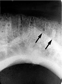
Mental Ridge
On periapical radiographs of the mandibular central incisors, the mental ridge (protuberance) may occasionally be seen as two radiopaque lines sweeping bilaterally forward and upward toward the midline (Fig. 10-45). They are of variable width and density and may be found to extend from low in the premolar area on each side up to the midline, where they lie just inferior to or are superimposed on the mandibular incisor tooth roots. The image of the mental ridge is most prominent when the beam is directed parallel with the surface of the mental tubercle (as when using the bisecting-angle technique).
Mental Fossa
The mental fossa is a depression on the labial aspect of the mandible extending laterally from the midline and above the mental ridge. Because of the resulting thinness of jawbone in this area, the image of this depression may be similar to that of the submandibular fossa (see later) and may, likewise, be mistaken for periapical disease involving the incisors (Fig. 10-46).
Mental Foramen
The mental foramen is usually the anterior limit of the inferior dental canal that is apparent on periapical radiographs (Fig. 10-47). Its image is quite variable, and it may be identified only about half the time because the opening of the mental canal is directed superiorly and posteriorly (Fig. 10-48). As a result, the usual view of the premolars is not projected through the long axis of the canal opening. This circumstance is responsible for the variable appearance of the mental foramen. Although the wall of the foramen is of cortical bone, the density of the foramen’s image varies, as does the shape and definition of its border. It may be round, oblong, slitlike, or very irregular and partially or completely corticated. The foramen is seen about halfway between the lower border of the mandible and the crest of the alveolar process, usually in the region of the apex of the second premolar. Also, because it lies on the surface of the mandible, the position of its image in relation to the tooth roots is influenced by projection angulation. It may be projected anywhere from just mesial of the permanent first molar roots to as far anterior as mesial of the first premolar root. The image of two mental foramina, one above the other, has also been observed.
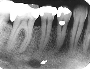
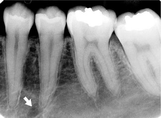
FIG. 10-47 The mental foramen (arrow) appears as an oval radiolucency near the apex of the second premolar.
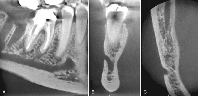
FIG. 10-48 Cone-beam Images Through Mental Foramen.
A, Oblique through body of mandible showing mandibular canal rising toward the mental foramen lying just anterior to apex of second premolar. B, Coronal section through mental foramen shows how the mandibular canal ascends to the mental foramen. This is important if implants are to be placed in this region. C, Axial section through mental foramen demonstrating posterior inclination of opening on mandibular surface. Note also section through mandibular canal posteriorly (top of image). (Images made with 3DX Accuitomo, J. Morita.)
When the mental foramen is projected over one of the premolar apices, it may mimic periapical disease (Fig. 10-49). In such cases, evidence of the inferior dental canal extending to the suspect radiolucency or a detectable lamina dura in the area would suggest the true nature of the dark shadow. It is well to point out, however, that the relative thinness of the lamina dura superimposed with the radiolucent foramen may result in considerable “burnout” of the lamina dura image, which will complicate its recognition. Nevertheless, a second radiograph from another angle is likely to show the lamina dura clearly, as well as some shift in position of the radiolucent foramen relative to the apex.
Mandibular Canal
The radiographic image of the mandibular canal is a dark linear shadow with thin radiopaque superior and inferior borders cast by the lamella of bone that bounds the canal (Fig. 10-50). Sometimes the borders are seen only partially or not at all. The width of the canal shows some interpatient variability but is usually rather constant anterior to the third molar region. The canal’s course may be apparent between the mandibular foramen and the mental foramen. Only rarely is the image of its anterior continuation toward the midline discernible on the radiograph.
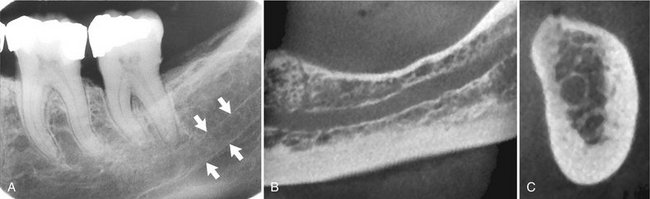
FIG. 10-50 Mandibular canal.
A, Arrows denote its radiopaque superior and inferior cortical borders on periapical view. B, Cone-beam section through body of mandible demonstrating corticated borders of mandibular canal. C, Cone-beam cross-sectional view demonstrating circular mandibular canal with corticated borders lying adjacent to lingual plate. (B and C made with 3DX Accuitomo, J. Morita.)
The relationship of the mandibular dental canal to the roots of the lower teeth may vary, from one in which there is close contact with all molars and the second premolar to one in which the canal has no intimate relationship to any of the posterior teeth. In the usual picture, however, the canal is in contact with the apex of the third molar, and the distance between it and the other roots increases as it progresses anteriorly. When the apices of the molars are projected over the canal, the lamina dura may be overexposed, conveying the impression of a missing lamina or a thickened PDL space that is more radiolucent than apparently normal for the patient (Fig. 10-51). To ensure the soundness of such a tooth, other clinical testing procedures must be used (e.g., vitality testing). Because the canal is usually located just inferior to the apices of the posterior teeth, altering the vertical angle for a second film of the area is not likely to separate the images of the apices and canal.
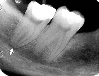
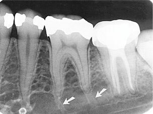
FIG. 10-51 The mandibular canal superimposed over the apex of a molar causes the image of the periodontal ligament space to appear wider (arrow). The presence of an intact lamina dura, however, indicates that there is no periapical disease.
Histologic studies have shown that the inferior alveolar nerve typically courses through the mandible as one major trunk with branches extending to the apices of the teeth. There are, however, multiple smaller branches of the inferior alveolar nerve running roughly parallel to the major trunk. Occasionally these branches are large enough that they have a secondary mandibular canal. Such bifid canals are seen most commonly on panoramic and cone-beam images (Fig. 10-52). Patients with bifid canals are at greater risk of inadequate anesthesia or difficulties with jaw surgery, including implants, or trauma.
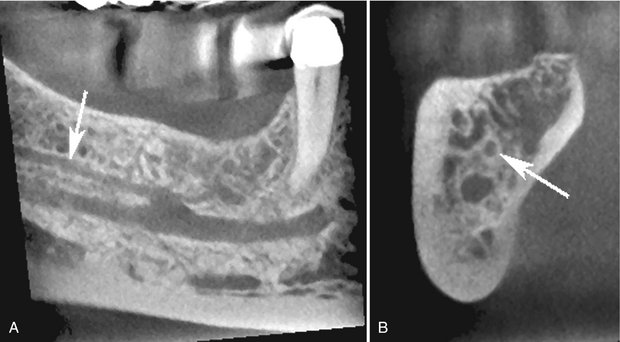
FIG. 10-52 Bifid Mandibular Canals.
A, Cone-beam section through body of mandible showing bifid mandibular canal. Superior branch has smaller diameter than the primary canal (arrow). B, Cross-sectional image showing primary canal and superior secondary canal (arrow). (Images made with 3DX Accuitomo, J. Morita.)
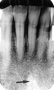
Nutrient Canals
Nutrient canals carry a neurovascular bundle and appear as radiolucent lines of fairly uniform width. They are most often seen on mandibular periapical radiographs running vertically from the inferior dental canal directly to the apex of a tooth (Fig. 10-53) or into the interdental space between the mandibular incisors (Fig. 10-54). They are visible in about 5% of all patients and are more frequent in blacks, males, older persons, and individuals with high blood pressure or advanced periodontal disease. They also indicate a thin ridge, useful in implant assessment. Because they are anatomic spaces with walls of cortical bone, their images occasionally have hyperostotic borders. At times a nutrient canal will be oriented perpendicular to the cortex and appear as a small round radiolucency simulating a pathologic radiolucency.
Mylohyoid Ridge
The mylohyoid ridge is a slightly irregular crest of bone on the lingual surface of the mandibular body. Extending from the area of the third molars to the lower border of the mandible in the region of the chin, it serves as an attachment for the mylohyoid muscle. Its radiographic image runs diagonally downward and forward from the area of the third molars to the premolar region, at approximately the level of the apices of the posterior teeth (Fig. 10-55). Sometimes this image is superimposed on the images of the molar roots. The margins of the image are not usually well defined but appear quite diffuse and of variable width. The contrary is also observed, however, where the ridge is relatively dense with sharply demarcated borders (Fig. 10-56). It will be more evident on periapical radiographs when the beam is positioned with excessive negative angulation. In general, as the ridge becomes less defined, its anterior and posterior limits blend gradually with the surrounding bone.
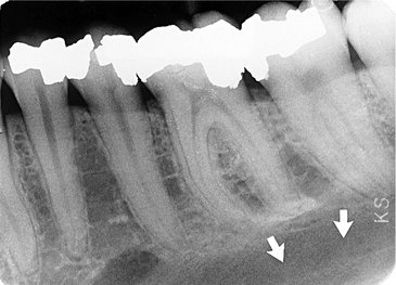
Submandibular Gland Fossa
On the lingual surface of the mandibular body, immediately below the mylohyoid ridge in the molar area, there is frequently a depression in the bone. This concavity accommodates the submandibular gland and often appears as a radiolucent area with the sparse trabecular pattern characteristic of the region (Fig. 10-57). This trabecular pattern is even less defined on radiographs of the area because it is superimposed on the relatively reduced mass of the concavity. The radiographic image of the fossa is sharply limited superiorly by the mylohyoid ridge and inferiorly by the lower border of the mandible but is poorly defined anteriorly (in the premolar region) and posteriorly (at about the ascending ramus). Although the image may appear strikingly radiolucent, accentuated as it is by the dense mylohyoid ridge and inferior border of the mandible, awareness of its possible presence should preclude its being confused with a bony lesion by the inexperienced clinician.
External Oblique Ridge
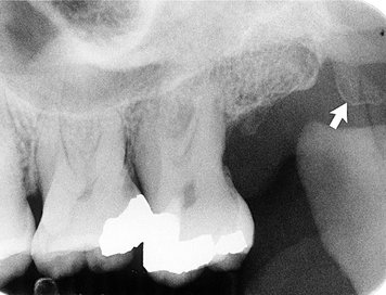
The external oblique ridge is a continuation of the anterior border of the mandibular ramus. It follows an anteroinferior course lateral to the alveolar process; it is relatively prominent in its upper part and juts considerably on the outer surface of the mandible in the region of the third molar (Fig. 10-58). This bony elevation gradually flattens, and usually disappears, at about where the alveolar process and mandible join below the first molar. The ridge is a line of attachment of the buccinator muscle. Characteristically, it is projected onto posterior periapical radiographs superior to the mylohyoid ridge, with which it runs an almost parallel course. It appears as a radiopaque line of varying width, density, and length, blending at its anterior end with the shadow of the alveolar bone.
Inferior Border of the Mandible
Occasionally the inferior mandibular border will be seen on periapical projections (Fig. 10-59) as a characteristically dense, broad radiopaque band of bone.
Coronoid Process
The image of the coronoid process of the mandible is frequently apparent on periapical radiographs of the maxillary molar region as a triangular radiopacity, with its apex directed superiorly and somewhat anteriorly, superimposed on the region of the third molar (Fig. 10-60). In some cases it may appear as far forward as the second molar and be projected above, over, or below these molars, depending on the position of the jaw and the projection of the x-ray beam. Usually the shadow of the coronoid process is homogeneous, although internal trabeculation can be seen in some cases. Its appearance on maxillary molar radiographs results from the downward and forward movement of the mandible when the mouth is open. Consequently, if the opacity reduces the diagnostic value of a film and the film must be remade, the second view should be acquired with the mouth minimally open. (This contingency must be considered whenever this area is radiographically examined.) On occasion, and especially when its shadow is dense and homogeneous, the coronoid process is mistaken for a root fragment by the neophyte clinician. The true nature of the shadow can be easily demonstrated by obtaining two radiographs with the mouth in different positions and noting the change in position of the suspect shadow.
Restorative Materials
Restorative materials vary in their radiographic appearance, depending primarily on their thickness, density, and atomic number. Of these, the atomic number is most influential.
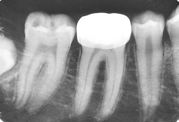
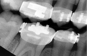
A variety of restorative materials may be recognized on intraoral radiographs. The most common, silver amalgam, is completely radiopaque (Fig. 10-61). Gold is equally opaque to x rays, whether cast as a crown or an inlay (Fig. 10-62) or condensed as gold foil. Stainless steel pins also appear radiopaque (Fig. 10-63). Often a calcium hydroxide base is placed in a deep cavity to protect the pulp. Although such base material may be radiolucent, most is radiopaque (Fig. 10-64). Another material of comparable radiopacity is gutta-percha, a rubberlike substance used to fill tooth canals during endodontic therapy (Fig. 10-65). Silver points were previously used to obliterate canals during endodontic therapy (Fig. 10-66). Other restorative materials that appear rather radiolucent on intraoral films include silicates, usually in combination with a base but now seldom used (Fig. 10-67), composite, usually in anterior teeth (Fig. 10-68), and porcelain, now usually fused to a metallic coping (Fig. 10-69). Composite restorative materials may also be opaque (Fig. 10-70). In addition, stainless steel crowns (Fig. 10-71) and orthodontic appliances around teeth (Fig. 10-72) are relatively radiopaque.
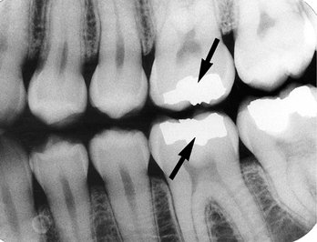
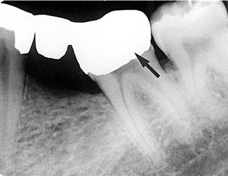
FIG. 10-62 A cast gold crown, appearing completely radiopaque (arrow), serves as the terminal abutment of a bridge.
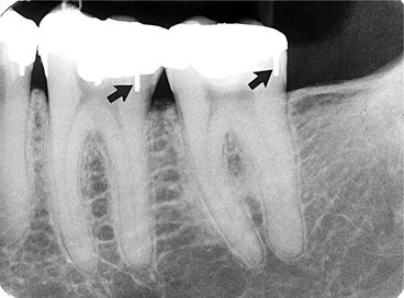
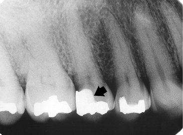
FIG. 10-64 Base material (arrow) is usually radiopaque but less opaque than the amalgam restoration.
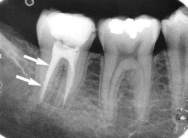
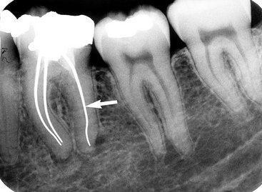
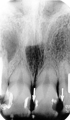
FIG. 10-67 Radiolucent silicate restorations (arrows) were placed over a base to protect the pulp in this patient.
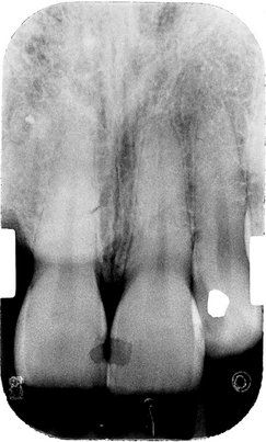
FIG. 10-68 Composite restorations may be radiolucent and may suggest caries but can be recognized by their well-demarcated border with dentin.
Berkovitz, BKB, Holland, GR, Moxham, BL. Oral anatomy, histology and embryology, ed 3. London: Mosby; 2002.
Claeys, V, Waskens, G. Bifid mandibular canal: literature review and case report. Dentomaxilofac Radiol. 2005;34:55–58.
Kasle, MJ. An atlas of dental radiographic anatomy, ed 4. Philadelphia: WB Saunders; 1994.
Liang, X, Jacobs, R, Lambrichts, I, et al. Lingual foramina on the mandibular midline revisited: a macroanatomical study. Clin Anat. 2007;20:246–251.
Lusting, JP, London, D, Dor, BL, et al. Ultrasound identification and quantitative measurement of blood supply to the anterior part of the mandible. Oral Surg Oral Med Oral Pathol Oral Radiol Endod. 2003;96:625–629.