Chapter 30 Trauma to the teeth and facial skeleton
INTRODUCTION
Injuries to the teeth and facial skeleton are, unfortunately, common. The type and severity of injuries can vary considerably, from minor damage to the teeth to grossly comminuted fractures of the skull.
Whatever the suspected injury, radiography is an essential requirement both in the initial assessment and in the follow-up appraisal. However, the radiographic examination may be restricted and limited by the general state of the patient and the type and severity of other injuries. For example, severe facial injuries are often associated with intracranial damage and/or cervical spine injuries, the importance of which far outweighs any damage to the teeth and their supporting structures. The radiographic investigation must therefore be tailored to each patient’s needs.
This chapter outlines the approach to radiographic investigation of trauma by separating injuries into four distinct categories:
INJURIES TO THE TEETH AND THEIR SUPPORTING STRUCTURES
Types of injury
Based broadly on the classification suggested by Andreasen and Andreasen (2001), the different types of dental injuries can be divided into:
Radiographic investigation
Although the type of injury may be evident clinically, radiographic investigation of all traumatized teeth is needed initially, to assess fully the degree of underlying damage. Radiographs are also required later to assess healing and/or the development of post-trauma complications. The ideal radiographic requirements include:
• Two views of the injured tooth from different angles, ideally at right angles to one another, but more usually with the X-ray tubehead in two different positions in the vertical plane. For example in the anterior region:
• Reproducible views to provide a base-line assessment and to allow subsequent follow-up evaluation
• Views of the chest and/or abdomen if a tooth or foreign body is thought to have been inhaled or swallowed, including:
Diagnostic information provided
The diagnostic information provided by these radiographs may include:
• The type of injury to the teeth
• The degree of displacement of the tooth fragments
• The stage of root development
• The condition of the apical tissues
• The presence, site and displacement of alveolar bone fractures
• The condition of adjacent or underlying teeth
Radiographic interpretation
The expected radiographic features indicating a fractured root are shown in Figure 30.1 and include:
• A radiolucent line between the fragments
• An alteration in the outline shape of the root and discontinuity of the periodontal ligament shadow.
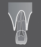
Fig. 30.1 Diagram illustrating the radiographic appearance of a theoretical root fracture showing a radiolucent line between the fragments, alteration in the outline shape of the root and discontinuity of the periodontal ligament shadow.
Examples of injured teeth and some of the more common post-injury complications evident radiographically, are shown in Figures 30.2 and 30.3.
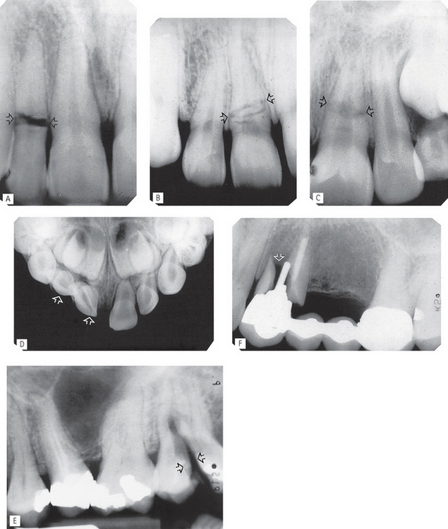
Fig. 30.2 Examples of traumatized teeth and their supporting structures. A Root fracture of  (arrowed), just beyond the cervical region, with wide separation of the fragments. B Root fracture of
  three radiolucent lines are evident, but only minimal separation of the fragments and disruption of the root outline (arrowed). C Root fracture of
  ; a broad radiolucent zone is evident across the root with marked discontinuity in root outline and the periodontal ligament shadow (arrowed). D Intrusion and fracture of
  (arrowed), but with no apparent displacement of the underlying permanent teeth. Intrusion is often associated with fracture of the labial bone (not evident on this view). E Vertical fracture of the crown and root of
  (arrowed). F Fracture of
  root (arrowed) with wide separation of the fragments owing to stresses transmitted through the post.
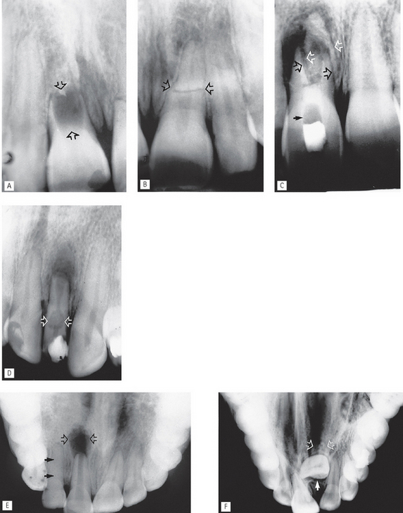
Fig. 30.3 Examples of common post-injury complications. A Immature root form following complete cessation of root development after death of  at the time of injury (arrowed). B
  of the same patient showing a complete, but abnormally shaped, root with (root) fracture (arrowed). The periodontal ligament shadow is continuous. C Apical infection and resorption of
  resulting in separation and displacement of the root fragments (open arrows). A radiopaque calcium hydroxide dressing is evident in the root canal with a radiopaque temporary restoration in the crown. The radiolucent area in between contains cottonwool (solid arrow). D Apical infection, external resorption of the apex and extensive internal root resorption (arrowed) of
  , following a coronal fracture involving the pulp. A radiopaque temporary dressing is evident in the crown. E Large area of apical infection associated with
  (open arrows). Root formation of
  has ceased and the apex is immature. In addition, the
  (damaged but not killed by the original trauma) shows complete sclerosis of the pulp chamber (solid arrows). F Severe dilaceration and non-eruption of
  (arrowed), following trauma to the deciduous incisors several years previously.
Limitations of radiographic interpretation of fractured roots
Unfortunately, as a result of the inherent limitations of a two-dimensional image, radiographic interpretation of traumatized teeth is not always as straightforward as Figures 30.2 and 30.3 may suggest.
As shown in Figure 30.4 the radiographic appearances can be influenced by:
• The position and severity of the fracture
• The degree of displacement or separation of the fragments
• The position of the film and X-ray tubehead in relation to the fracture line(s).
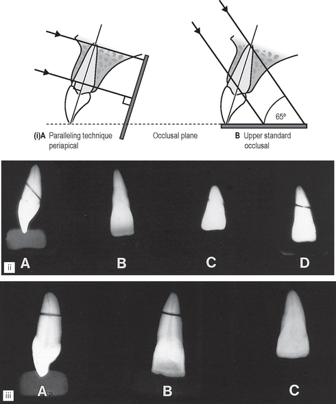
Fig. 30.4 (i) Diagram showing the difference in vertical angulation of the X-ray tubehead. A For a paralleling technique periapical. B An upper standard occlusal of the maxillary incisors. (ii) The different radiographic appearances of a tangential root fracture using different projections. A From the side showing the direction of the fracture and separation of the fragments. B Using a horizontal X-ray beam. C Using a steeply angled (75°) X-ray beam. D Using an angled (65°) X-ray beam. (iii) The different radiographic appearances of a horizontal root fracture. A From the side. B Using a horizontal X-ray beam. C Using an angled (65°) X-ray beam.
It is for these reasons that a minimum of two views, from two different angles, is essential.
SKELETAL FRACTURES
As mentioned earlier, radiographs are an essential part of the initial assessment and follow-up appraisal of all patients with suspected facial fractures. They are crucial in evaluating:
• The site and direction of the fracture line(s)
• The degree of displacement and separation of the bone ends
• The relationship of teeth to the fracture line
• The location of associated foreign bodies in hard and soft tissues
• The presence of coincidental or contributory disease
• The alignment of the bone fragments after treatment
• Healing and the identification of post-trauma complications including infection, non-union or malunion.
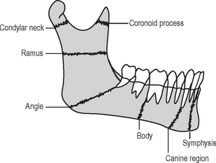
FRACTURES OF THE MANDIBLE
• Where the mandible tends to fracture
• Which radiographic views are required to show each of the fracture sites
• What radiological features indicate the presence of fracture(s)
Radiographic projections required
Several different views are used to show the various fracture sites. Once again, the ideal minimum requirement in all cases is two views at right angles to one another. When that is not possible, two views at two different angles should be used. In addition, intraoral views (either periapicals or occlusals) are required when fractures are in the tooth-bearing portion of the mandible and teeth are involved in the fracture line. The typical projections that can be used for the different sites are summarized in Table 30.1.
Table 30.1 Summary of the main mandibular fracture sites and the common radiographic projections used for each site
| Fracture site | Commonly used radiographs |
|---|---|
| Angle | |
| Condylar neck | |
| Body | |
| Canine region | |
| Symphysis | |
| Ramus | |
| Coronoid process |
Radiological features of mandibular fractures (Fig. 30.6)
The typical radiographic appearances include:
• Radiolucent line(s) between the bone fragments if they are separated. Note that fractures through the buccal and lingual cortical plates may produce two radiolucent lines
• A radiopaque line if the fragments overlie one another
• An alteration in the outline of the bone if the fragments are displaced, producing a step deformity of the lower border or the occlusal plane.
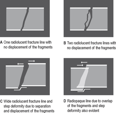
Fig. 30.6 Diagrams illustrating the radiographic appearances of fractures depending on the bony displacement, separation or overlap that could be present.
Important points to note
• The extent/severity of any displacement depends on:
• If the fracture line runs in such a manner that the associated muscles tend to hold the fragments together, the fracture is described as favourable
• If the associated muscles tend to pull the fragments apart, the fracture is described as unfavourable.
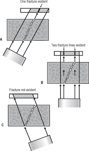
Radiographic limitations
As mentioned earlier, the limitations of the radiographic image mean that these appearances can be influenced by:
• The position and severity of the fracture
• The degree of displacement or separation of the fragments
• The position of the film and X-ray tubehead in relation to the fracture line(s), as shown in Figure 30.7.
Interpretation of fractures
To emphasize, yet again, the importance of the principles outlined in Chapter 20, before any attempt is made to diagnose a fracture the quality of the radiographs should be assessed.
While doing the overall critical assessment, it is worth remembering that many patients who have recently been injured may be very difficult to radiograph because of pain, medication, overlying soft tissue wound dressings or other injuries which they may have sustained at the same time. In addition, blood in the antra, nose and pharynx may adversely affect film contrast.
Clinicians should not be too critical of the radiographer; the radiographs obtained are probably the best possible under the circumstances. However, due allowance should be made for these likely technique difficulties when interpreting the final radiographs.
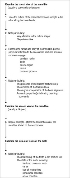
Systematic approach
A suggested sequence for examining radiographs when attempting to diagnose mandibular fractures is shown in Figure 30.8.
Examples of mandibular fractures
Examples of fractures of different sites of the mandible, preoperatively and postoperatively, are shown in Figures 30.9-30.17.
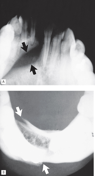
Fig. 30.9 A Lower 45° occlusal and B Lower 90° occlusal showing a fracture in the symphyseal region (arrowed). Note the lower 45° occlusal shows the displacement in the vertical plane, while the lower 90° occlusal shows the displacement in the horizontal plane.
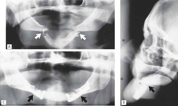
Fig. 30.10 A Panoramic radiograph showing bilateral fractures of the canine region, so-called bucket handle fractures (arrowed), after the first attempted fixation with intra-osseous wires. B True lateral skull. Note the extensive displacement of the anterior segment of the mandible owing to the unopposed pull of the muscles attached to this fragment. This is described as an unfavourable fracture. The inadequate intra-osseous wires are again evident. C Panoramic radiograph after fixation with bone plates (arrowed).
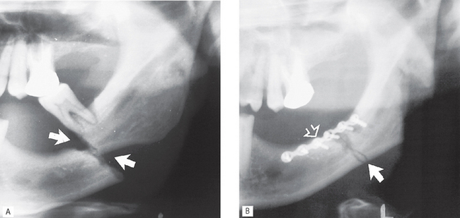
Fig. 30.11 A Left side of a panoramic radiograph showing an unfavourable markedly displaced fracture of the body of the mandible (arrowed). B Left side of a panoramic radiograph taken postoperatively showing accurate reduction of the fragments (solid arrow) and fixation with a bone plate (open arrow). The lower molar has been extracted.
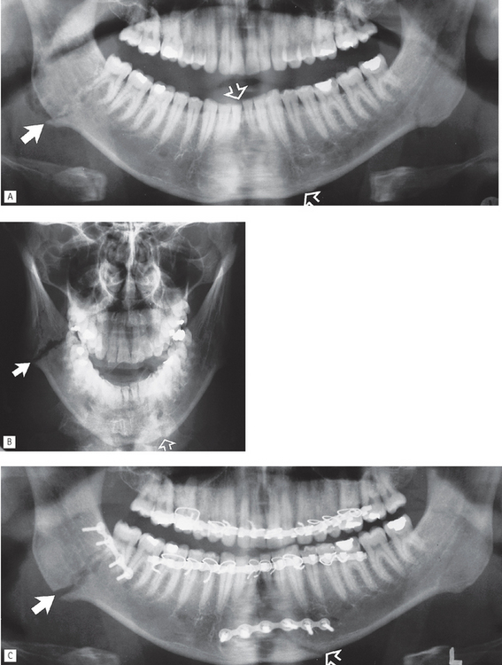
Fig. 30.12 A Panoramic radiograph showing bilateral fracture of the mandible — through the right angle and symphyseal/left canine region. Note that the fracture through the angle appears radiopaque as the bony fragments are overlying one another (solid arrow) and that the symphyseal/canine region fracture (open arrow) is almost totally obscured by the overlying ghost shadow of the cervical spine. B PA jaws showing the fracture through the angle clearly as a radiolucent line (solid arrow) while the symphyseal/canine region fracture is still difficult to see (open arrow) as a result of superimposition of the cervical spine. C Postoperative panoramic radiograph showing reduction and fixation of the bone fragments (arrowed) using bone plates. Arch bars and islet wiring around the teeth are also evident.
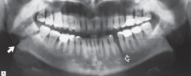
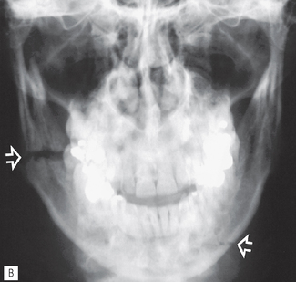
Fig. 30.13 A Panoramic radiograph showing a bilateral fracture of the mandible through the right angle (solid arrow) and left body (open arrow) with minimal displacement.
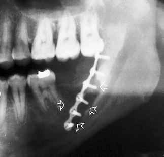
Fig. 30.14 Left side of a panoramic radiograph showing extensive bone resorption (arrowed) as a result of infection around a bone plate that had been used for fracture fixation.
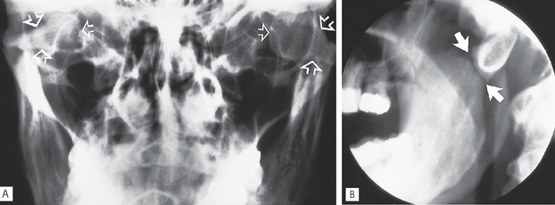
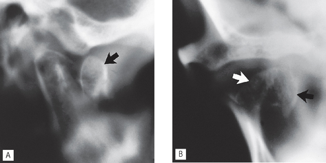
Fig. 30.15 A Central portion of a PA jaws showing bilateral fractures of the condylar necks with marked medial displacement of both condylar heads (arrowed). B An oblique lateral of the left side showing the fracture line (arrowed). Note that although the condylar shape is altered, it is not possible to deduce whether it has been displaced medially or laterally from the oblique lateral view alone.
FRACTURES OF THE MIDDLE THIRD OF THE FACIAL SKELETON
This is probably one of the most difficult and confusing topics in dental radiology. The problem now concerns multiple-bone fractures instead of the relatively simple one-bone fractures encountered with the mandible. Owing to the complexity of the facial skeleton, there is a fundamental requirement of a sound knowledge of anatomy.
In addition, the knowledge required by the clinician can again be summarized as follows:
• Where the middle third of the face tends to fracture
• Which radiographic views are required to show each of the fracture sites
• What radiological features indicate the presence of fracture(s)
Classification and the main fracture sites
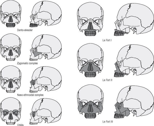
Most injuries to the middle third of the face are from the front, forcing part or parts of the facial skeleton downwards and backwards along the cranial base. The resulting lines of fracture follow the lines of weakness of the facial skeleton, as shown in Figure 30.18. This allows a broad classification based on site, as follows:
• Central middle third fractures, including:
• Fractures of the zygomatic complex, including:
Radiographic investigation
As mentioned earlier, radiographic investigation of facial fractures depends upon available facilities, the general state of the patient, associated injuries, particularly intracranial and spinal (odontoid peg), and the severity of the facial trauma.
Nevertheless, in all cases radiographic investigation should include a true lateral skull projection to exclude fractures of the cranial base, a characteristic feature of which is the presence of a fluid level in the sphenoidal air sinus.
Important points to note
• In a casualty department, the patient is usually X-rayed lying down as shown in Chapter 14. The true lateral projection should be taken with the patient supine (brow up), and with the X-ray beam horizontal, to show the possible fluid level. This projection is therefore sometimes referred to as a brow-up lateral or shoot-through lateral (see Fig. 14.1A).
• The projections that can be used for the different fracture sites are summarized in Table 30.2. Again the principle of requiring a minimum of two views at right angles applies but, as indicated, several views may be necessary.
• A useful tip to remember is that the occipitomental radiographs should be viewed initially from a distance of about a metre to allow an easy comparison of both sides and to detect any facial asymmetry.
Table 30.2 Summary of the common radiographic projections used to show the various middle third fracture sites
| Fracture type/site | Commonly used investigations |
|---|---|
| Dento-alveolar | |
| Le Fort I | |
| Le Fort II | |
| Le Fort III | |
| Zygomatic complex | |
| Naso-ethmoidal complex | |
| Orbit |
Interpretation of middle third fractures
Systematic approach
In view of the numerous possible fracture sites, an ordered sequence to viewing is essential. One suggested approach can be summarized as follows:
• Examine the 0° OM using an approach based broadly on that suggested originally by McGrigor and Campbell (1950), often referred to as Campbell’s lines (Fig. 30.19).
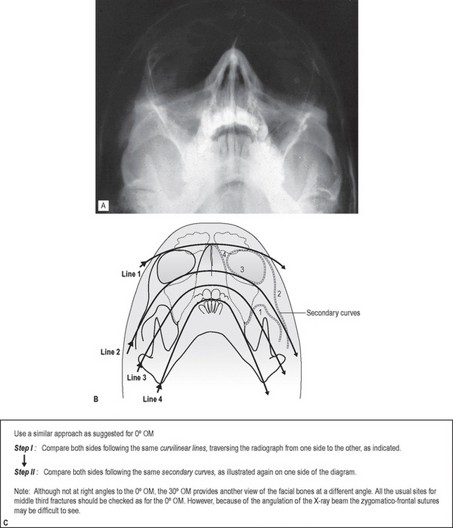
• Examine the 30° OM as shown in Figure 30.20.
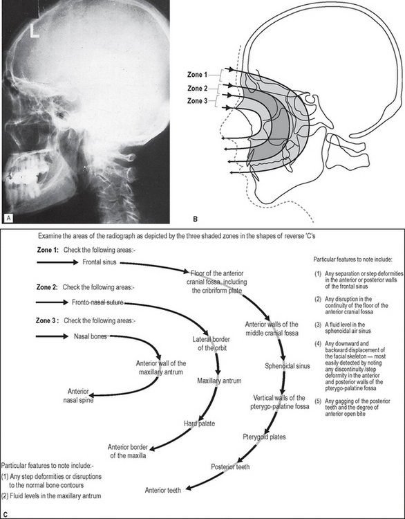
• Examine the true lateral skull as shown in Figure 30.21.
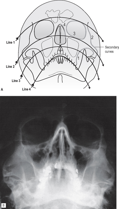
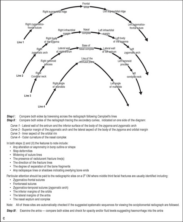
Fig. 30.19 Suggested systematic approach to interpretation of the 0° OM. A Diagram of a 0° OM showing Campbell’s curvilinear lines and the secondary curves. B An example of a 0° occipitomental. C An explanation of Campbell’s lines and the secondary curves.
Examples of middle third facial fractures
Examples of injuries to different parts of the facial skeleton are shown in Figures 30.22-30.29.
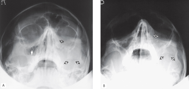
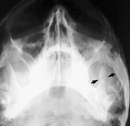
Fig. 30.22 A 0° OM and B 30° OM showing a fracture of the left zygomatic complex. Three of the usual fracture sites are arrowed: the lower border of the orbit, the zygomatico-temporal suture (zygomatic arch) and the lateral wall of the antrum. There is a fluid level evident in the right antrum (white arrow).
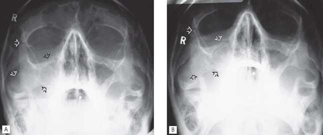
Fig. 30.23 A 0° OM and B 30° OM showing a fracture of the right zygomatic complex. The main fracture sites are arrowed.
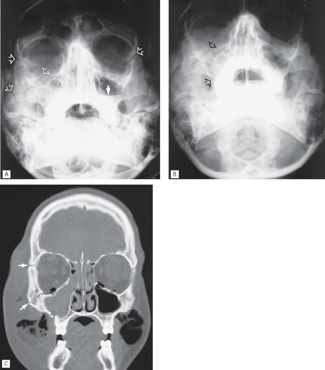
Fig. 30.24 A 0° OM, B 30° OM and C Coronal section CT of different patients showing multiple middle third fracture sites, the more obvious of which are arrowed. In addition, the CT scan shows the right antrum to be totally opaque, the extensive soft tissue swelling and air in the orbits and soft tissues.
(Kindly supplied by Dr J. Luker.)
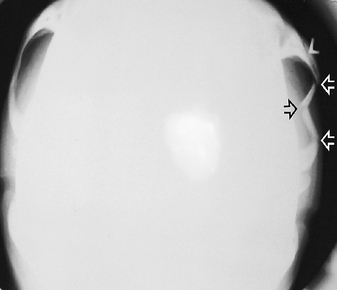
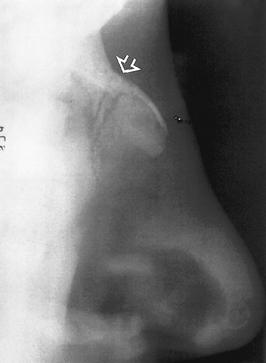
Fig. 30.25 Submentovertex (reduced exposure) showing a depressed fracture of the left zygomatic arch. Typically this type of injury results in three fracture sites which are arrowed.
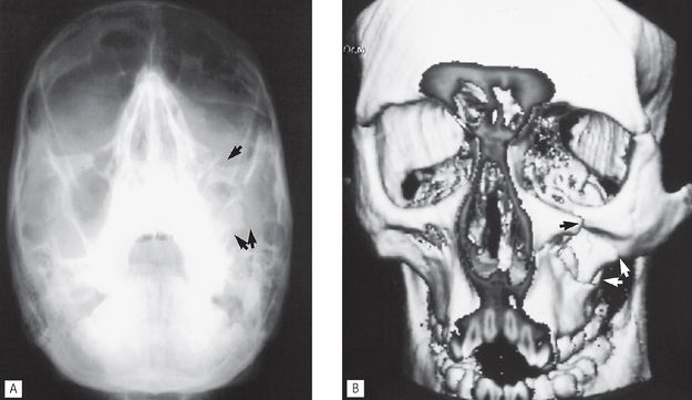
Fig. 30.26 A OM and B three-dimensional reconstructed CT scan showing a fracture of the left zygomatic complex. The more obvious fracture sites are arrowed.
(Kindly supplied by Mr N. Drage.)
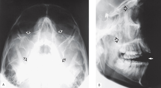
Fig. 30.27 A 30° OM and B true lateral skull showing Le Fort II fracture. The more obvious fractures are arrowed including the pterygopalatine fossa walls. As a result of the backward displacement of the facial skeleton the posterior teeth are in occlusion and there is an anterior open bite (solid arrow).
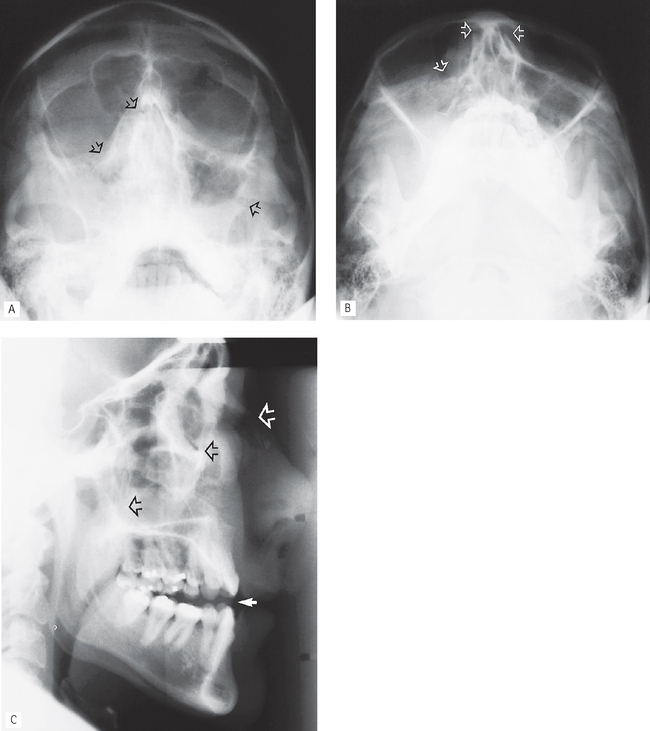
Fig. 30.28 A 0° OM and B 30° OM and C true lateral skull showing multiple middle facial fractures including the nasal complex (arrowed). The facial skeleton has again been displaced backwards producing an anterior open bite.
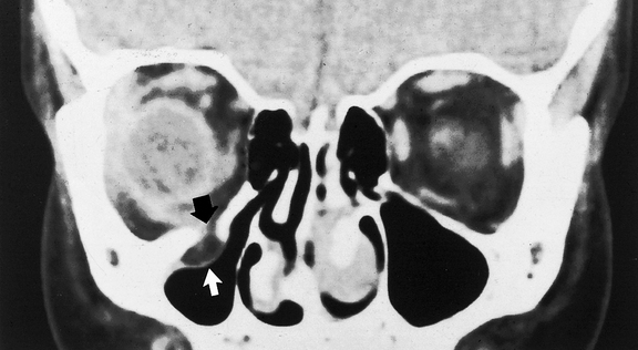
Orbital blow-out fracture
Following a direct blow to the globe of the eye, the orbital rim remains intact but the force of the blow is transmitted either downwards or medially. The very thin bones of the orbital floor can break and allow the contents of the globe to herniate downwards into the antrum. Superimposition on conventional radiographs makes this type of fracture difficult to detect, hence the need for CT (if available) or cone beam CT to determine the site and severity of the injury (see Fig. 30.30).
OTHER FRACTURES AND INJURIES
Facial fractures are often associated with some other injury involving the head and neck. These can be divided broadly into:
It is beyond the scope of this book to discuss these injuries in detail, but the more commonly used radiographic investigations are summarized in Table 30.3.
Table 30.3 Summary of the commonly used radiographic investigations for fractures of the cranium, cervical spine and intracranial injuries
| Fracture type/site | Commonly used investigations |
|---|---|
| Skull vault | |
| Cranial base | |
| Cervical spine | |
| Intracranial injuries |