Chapter 14 Skull and maxillofacial radiography
Radiographs of the whole head may be required for a variety of purposes. However, the complexity of the structure of the maxillofacial skeleton, the base of the skull and the temporomandibular joint (TMJ) means that many different projections have had to be devised. They are gradually being replaced by cone beam (CT) (see Ch. 19) as this equipment becomes more widely available.
MAIN INDICATIONS
The main clinical indications requiring radiographs of the skull and maxillofacial skeleton include:
EQUIPMENT
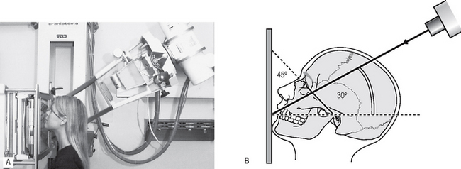
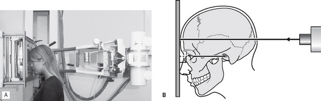
Most skull radiographs are taken using either an isocentric skull unit such as the Orbix®, often with the patient lying down, or using a conventional skull unit such as the Craniotome® with the patient sitting up as shown in Figure 14.1.
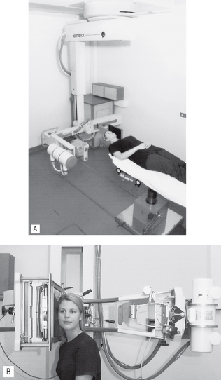
Fig. 14.1 A Patient supine in the Orbix® skull unit and B erect in the Craniotome®. In both X-ray units, the patient is positioned to produce a lateral view of the skull.
The image receptor is commonly a cassette (18 × 24 cm) containing either conventional intensifying screens and indirect-action film or an appropriately sized digital phosphor plate (see Ch. 6)
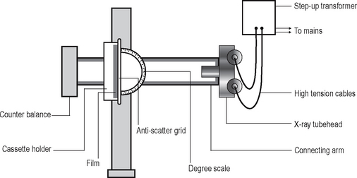
The basic components of the Craniotome® shown in Figure 14.2 include:
• X-ray generating apparatus that is:
• Counter balance, to allow easy positioning of the very heavy tubehead
• Degree scale, so the X-ray tubehead can be set at specific vertical angulations for different projections
• Anti-scatter grid, designed originally to be used with film-based radiography to stop the photons scattered within the patient from reaching the film (see Ch. 2). These scattered photons would degrade the final overall image quality. The design and function of the anti-scatter grid is shown in Figure 14.3. As some of the photons are absorbed by the lead strips in the grid, a higher dose of radiation is required to ensure sufficient photons reach the film. There are two types of grid:
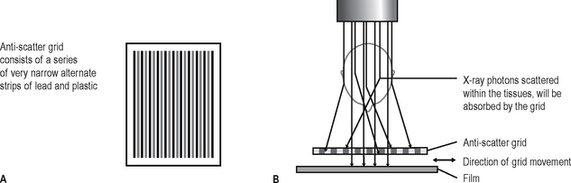
When using digital phosphor plates as the image receptor and similar exposure factors, insufficient photons penetrate the grid for an acceptable image to be obtained. Either the exposure factors (kV) have to be increased or the grid has to be removed.
PATIENT POSITIONING
The positioning of the patient for skull radiography depends on the general condition of the patient, particularly following trauma, and the equipment available. With the isocentric Orbix®, the patient simply remains supine and the equipment is rotated around the head to produce the required projections as shown in Figure 14.4A and B. Using the Craniotome®, as described in this chapter, the patient’s head and the equipment are moved into different positions.
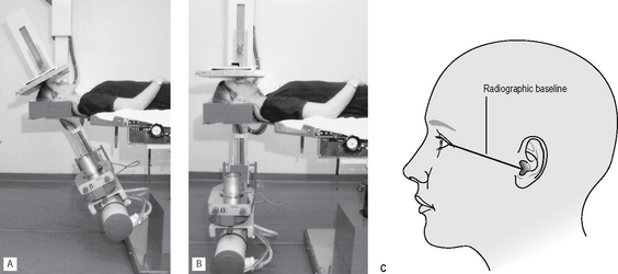
Fig. 14.4 Patient positioned in the Orbix® for A a posteroanterior (PA) projection and B a reverse Towne’s projection. C Diagram showing the radiographic baseline extending from the outer canthus of the eye to the external auditory meatus.
Positioning the head is facilitated by the radiographic baseline — a line representing the base of the skull. It extends from the outer canthus of the eye to the external auditory meatus and is sometimes referred to as the orbitomeatal line (see Fig. 14.4C).
In the photographs and diagrams of the positioning techniques, the radiographic baseline has been drawn on the patient’s face so it can be seen clearly.
MAIN MAXILLOFACIAL/SKULL PROJECTIONS
• Standard occipitomental (0° OM)
• Posteroanterior of the skull (PA skull) sometimes referred to as occipitofrontal (OF)
• Posteroanterior of the jaws (PA jaws)
This terminology complies with the British Standards Glossary of Dental Terminology (BS 4492: 1983). It may seem confusing, but most of the views are named according to the direction the X-ray beam is travelling, e.g. for occipitomental (OM) views the X-ray beam is travelling from the occipital region to the mental region, for transpharyngeal views the X-ray beam is travelling across the pharynx.
Each of these projections will now be described in detail, except for the transpharyngeal which is used specifically for the TMJ and is discussed in Chapter 31.
Once again the format used is based on the essential knowledge required by clinicians, namely:
• WHY each projection is taken
• WHAT the resultant radiograph should look like and which normal anatomical features it shows.
Standard occipitomental (0° OM)
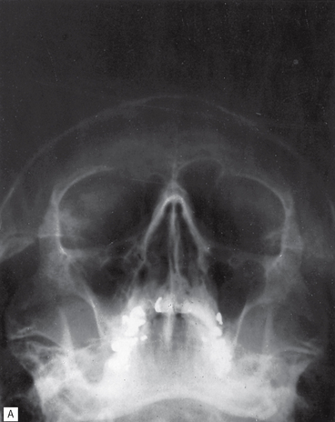
This projection shows the facial skeleton and maxillary antra, and avoids superimposition of the dense bones of the base of the skull.
Main indications
Technique and positioning
This can be summarized as follows:
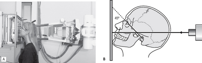
1. The patient is positioned facing the image receptor with the head tipped back so the radiographic baseline is at 45° to the image receptor, the so-called nose–chin position. This positioning drops the dense bones of the base of the skull downwards and raises the facial bones so they can be seen.
2. The X-ray tubehead is positioned with the central ray horizontal (0°) centred through the occiput (see Fig. 14.5B).
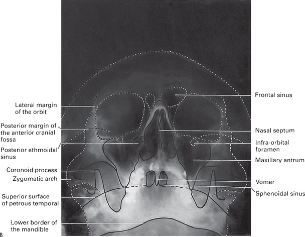
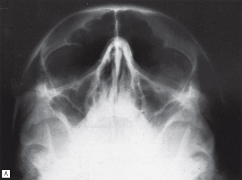
30° occipitomental (30° OM)
This projection also shows the facial skeleton, but from a different angle from the 0° OM, enabling certain bony displacements to be detected.
Main indications
The main clinical indications include:
Note: Ideally for fracture diagnosis two views at right angles are required (see Ch. 30), but the 0° OM and 30° OM provide two views of the facial bones at two different angles — therefore in cases of suspected facial fracture both views are needed.
Technique and positioning
This can be summarized as follows:
1. The patient is in exactly the same position as for the 0° OM, i.e. the head tipped back, radiographic baseline at 45° to the image receptor, in the nose–chin position.
2. The X-ray tubehead is aimed downwards from above the head, with the central ray at 30° to the horizontal, centred through the lower border of the orbit (see Fig. 14.7).
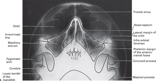
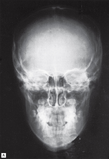
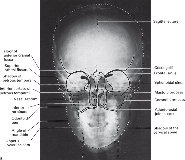
Posteroanterior of the skull (PA skull)
This projection shows the skull vault, primarily the frontal bones and the jaws.
Technique and positioning
This can be summarized as follows:
1. The patient is positioned facing the image receptor with the head tipped forwards so that the forehead and tip of the nose touch the image receptor — the so-called forehead–nose position. The radiographic baseline is horizontal and at right angles to the image receptor. This positioning levels off the base of the skull and allows the vault of the skull to be seen without superimposition.
2. The X-ray tubehead is positioned with the central ray horizontal (0°) centred through the occiput (see Fig. 14.9).
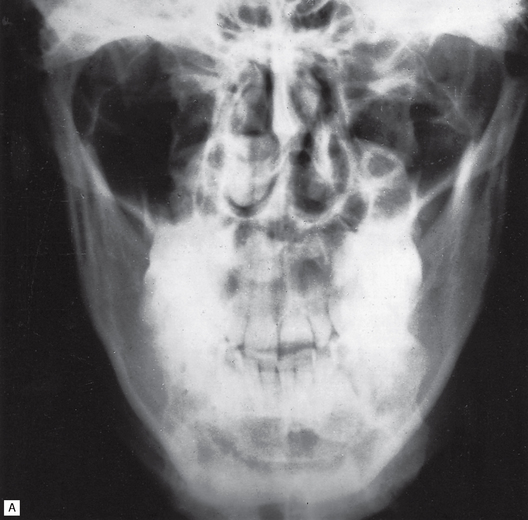
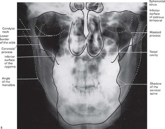
Posteroanterior of the jaws (PA jaws/PA mandible)
This projection shows the posterior parts of the mandible. It is not suitable for showing the facial skeleton because of superimposition of the base of the skull and the nasal bones.
Main indications
Technique and positioning
This can be summarized as follows:
1. The patient is in exactly the same position as for the PA skull, i.e. the head tipped forward, the radiographic baseline horizontal and perpendicular to the image receptor in the forehead–nose position.
2. The X-ray tubehead is again horizontal (0°), but now the central ray is centred through the cervical spine at the level of the rami of the mandible (see Fig. 14.11).

Fig. 14.11 A Positioning for the PA jaws/PA mandible projection — the patient is in the forehead–nose position and the X-ray beam is horizontal centred through the rami. B Diagram of the positioning — the radiographic baseline is horizontal and perpendicular to the image receptor, and the X-ray beam is also horizontal.
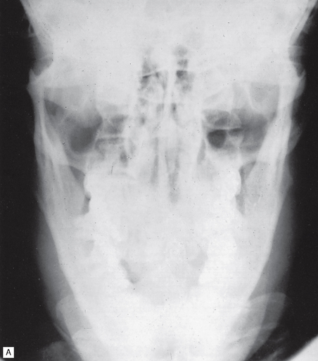
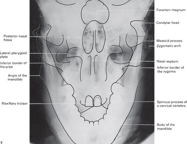
Reverse Towne’s
This projection shows the condylar heads and necks. The original Towne’s view (an AP projection) was designed to show the occipital region, but also showed the condyles. However, since all skull views used in dentistry are taken conventionally in the posterior-anterior direction, the reverse Towne’s (a PA projection) is used.
Technique and positioning
This can be summarized as follows:
1. The patient is in the PA position, i.e. the head tipped forwards in the forehead–nose position, but in addition the mouth is open. The radiographic baseline is horizontal and at right angles to the image receptor. Opening the mouth takes the condylar heads out of the glenoid fossae so they can be seen.
2. The X-ray tubehead is aimed upwards from below the occiput, with the central ray at 30° to the horizontal, centred through the condyles (see Fig. 14.13).
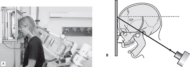
Fig. 14.13 A Positioning for the reverse Towne’s projection — the patient is in the forehead–nose position with the mouth open and the X-ray beam is aimed upwards at 30°. B Diagram of the positioning — the radiographic baseline is horizontal and perpendicular to the image receptor, the mouth is open and the X-ray beam is aimed upwards at 30°.
Rotated posteroanterior (rotated PA)
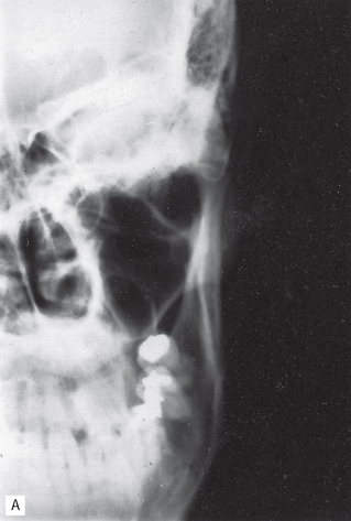
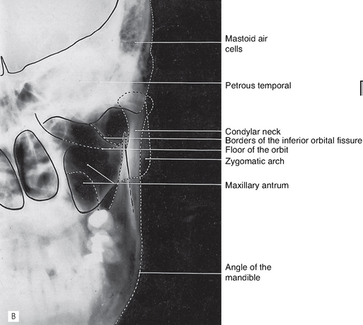
This projection shows the tissues of one side of the face and is used to investigate the parotid gland and the ramus of the mandible.
Technique and positioning
This can be summarized as follows:
1. The patient is positioned facing the image receptor, with the occlusal plane horizontal and the tip of the nose touching the image receptor in the so-called normal head position.
2. The head is then rotated 10° to the side of interest. This positioning rotates the bones of the back of the skull away from the side of the face under investigation.
3. The X-ray tubehead is positioned with the central ray horizontal (0°), aimed down the side of the face (see Fig. 14.15).
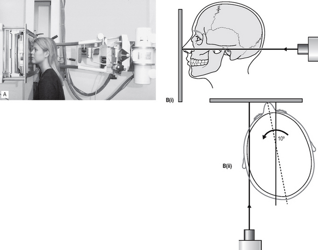
Fig. 14.15 A Positioning for the rotated PA projection — the patient is in the normal head position and rotated to the side of interest and the X-ray beam is horizontal. B Diagrams of the positioning (i) from the side, normal head position and the X-ray beam horizontal, (ii) from above, 10° rotation of the head to the side of interest and the X-ray beam aimed along the side of the face.
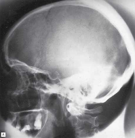
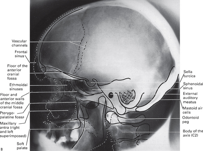
True lateral skull
This projection shows the skull vault and facial skeleton from the lateral aspect. The main difference between the true lateral skull and the true cephalometric lateral skull taken on the cephalostat (see Ch. 15) is that the true lateral skull is not standardized or reproducible. This view is used when a single lateral view of the skull is required but not in orthodontics or growth studies.
Main indications
Technique and positioning
This can be summarized as follows:
1. The patient is positioned with the head turned through 90°, so the side of the face touches the image receptor. In this position, the sagittal plane of the head is parallel to the image receptor.
2. The X-ray tubehead is positioned with the central ray horizontal (0°) and perpendicular to the sagittal plane and the image receptor, centred through the external auditory meatus (see Fig. 14.17).
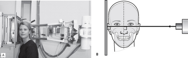
Fig. 14.17 A Positioning for the true lateral skull projection — the patient’s head is turned through 90°, and the X-ray beam is horizontal. B Diagram of the positioning — the sagittal plane of the head is parallel to the image receptor and the X-ray beam is horizontal and perpendicular to the sagittal plane and the image receptor.
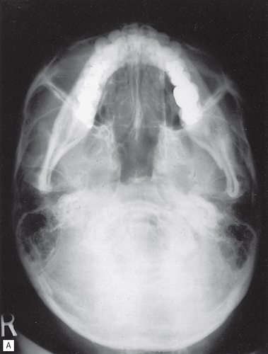
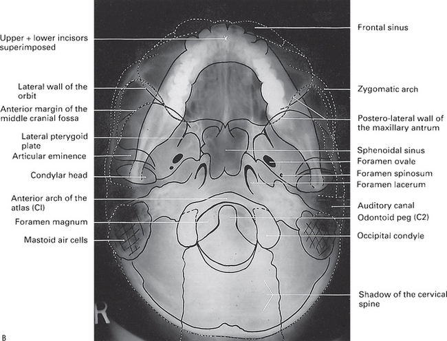
Submentovertex (SMV)
This projection shows the base of the skull, sphenoidal sinuses and facial skeleton from below.
Main indications
The main clinical indications include:
• Destructive/expansive lesions affecting the palate, pterygoid region or base of skull
• Investigation of the sphenoidal sinus
• Assessment of the thickness (mediolateral) of the posterior part of the mandible before osteotomy
• Fracture of the zygomatic arches — to show these thin bones the SMV is taken with reduced exposure factors.
Technique and positioning
This can be summarized as follows:
1. The patient is positioned facing away from the image receptor. The head is tipped backwards as far as is possible, so the vertex of the skull touches the image receptor. In this position, the radiographic baseline is vertical and parallel to the image receptor.
2. The X-ray tubehead is aimed upwards from below the chin, with the central ray at 5° to the horizontal, centred on an imaginary line joining the lower first molars (see Fig. 14.19).
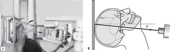
Fig. 14.19 A Positioning for the SMV projection — the patient’s head is tipped backwards and the X-ray beam is aimed upwards at 5° to the horizontal. B Diagram of the positioning — the radiographic baseline is vertical and parallel to the image receptor and the X-ray beam is aimed upwards at 5° to the horizontal.
Note: The head positioning required for this projection means it is contraindicated in patients with suspected neck injuries, especially suspected fracture of the odontoid peg.