Chapter 33 The salivary glands
SALIVARY GLAND DISORDERS
Disorders of the major salivary glands are relatively common, with a large spectrum of underlying diseases. This has led to a variety of classifications. However, the presenting symptoms and complaints allow a broad division into six main categories:
• Acute intermittent generalized swelling of a gland, often related to meals
• Acute generalized swelling of one or more glands
• Chronic generalized swelling, often involving more than one gland
The important causes of these complaints are summarized in Table 33.1.
Table 33.1 A summary of the main salivary gland complaints and their causes
| Salivary gland complaint | Cause |
|---|---|
| Acute intermittent generalized swelling | |
| Acute generalized swelling | |
| Chronic generalized swelling | |
| Discrete swelling | |
| Dry mouth | |
| Excess salivation |
INVESTIGATIONS
Several investigations can be used on the salivary glands, the most appropriate often being decided by the patient’s presenting symptoms. The main investigations include:
Plain radiography
The most common disorder of the major salivary glands is obstruction caused either by salivary stones (calculi) or stricture of the ducts. A large proportion of salivary calculi are radiopaque (approximately 40–60% in the parotid and 80% in the submandibular glands) so patients presenting with obstructive symptoms of acute intermittent swelling require routine radiographs to determine the presence and position of the stone(s), as shown in Figure 33.1.
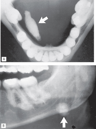
Fig. 33.1 A Lower 90° occlusal showing a large radiopaque calculus (arrowed) in the right submandibular duct. B Part of a panoramic radiograph showing another calculus (arrowed) in the left submandibular gland.
The radiographic projections used commonly for the parotid and submandibular glands are summarized in Table 33.2.
Table 33.2 A summary of the commonly used radiographic projections for the parotid and submandibular glands
| Salivary gland | Radiographic projections used |
|---|---|
| Parotid | |
| Submandibular |
Sialography
Sialography can be defined as the radiographic demonstration of the major salivary glands by introducing a radiopaque contrast medium into their ductal system. It is also very effective for the diagnosis of obstruction whether caused by stones or strictures. It is widely used and is probably still the most common specialized salivary gland investigation.
The procedure is divided into three phases.
Preoperative phase
This involves taking preoperative (scout) radiographs, if not already taken, before the introduction of the contrast medium, for the following reasons:
Filling phase
The relevant duct orifice needs to be found clinically, probed and dilated, and then cannulated. This is shown in Figure 33.2. together with a diagram of the normal anatomy of the major salivary glands and ducts. The contrast medium can then be introduced.
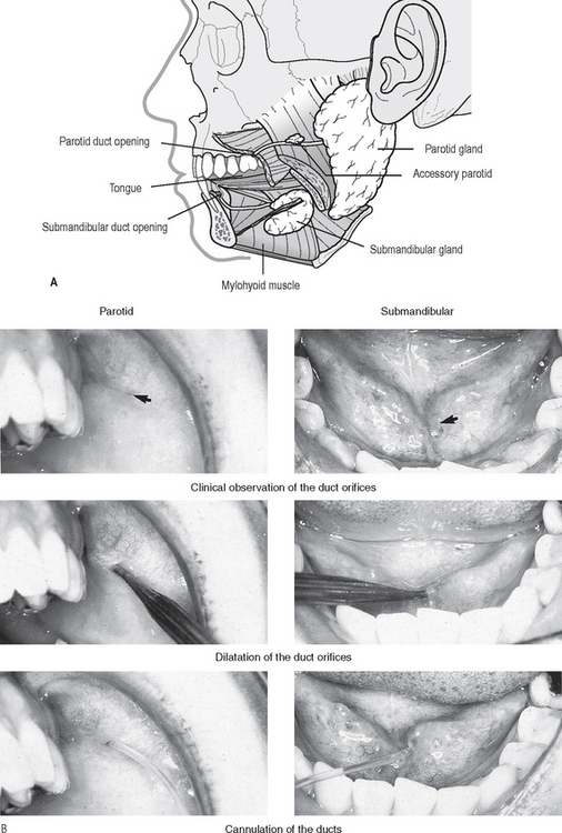
Fig. 33.2 A Diagram showing the normal anatomy of the parotid and submandibular salivary glands, ducts and duct orifices. B Clinical photographs showing these duct orifices (arrowed), being dilated and cannulated.
Three main techniques are available for introducing the contrast medium, as described later. When this is complete, the filling phase radiographs are taken, ideally at least two different views at right angles to one another.
Emptying phase
The cannula is removed and the patient allowed to rinse out. The use of lemon juice at this stage to aid excretion of the contrast medium is often advocated but is seldom necessary. After one and five minutes, the emptying phase radiographs are taken, usually oblique laterals. These films can be used as a crude assessment of function.
Contrast media used
The types of contrast media (see Ch. 19) suitable for sialography are all iodine-based, and include:
Most radiology departments use aqueous solutions. Their relative advantages and disadvantages are summarized in Table 33.3.
Table 33.3 A summary of the advantages and disadvantages of oil-based and aqueous contrast media
| Contrast medium | Advantages | Disadvantages |
|---|---|---|
| Oil-based | ||
| Aqueous |
Note: Since the contrast medium is not being introduced into the bloodstream, there is no need to use the safer, but more expensive, non-ionic contrast media discussed in Chapter 19.
Contraindications
The main contraindications include:
• Allergy to compounds containing iodine although gadolinium may be used as an alternative
• Periods of acute infection/inflammation, when there is discharge of pus from the duct opening
• When clinical examination or routine radiographs have shown a calculus close to the duct opening, as injection of the contrast medium may push the calculus back down the main duct where it may be inaccessible.
Sialographic techniques
The control of infection measures detailed in Chapter 9 are of particular importance, and should be adhered to during sialography. In addition, the wearing of eye protection glasses and a mask by operators is recommended.
The three main techniques available for introducing the contrast medium into the ductal system, having cannulated the relevant duct orifice, include:
These techniques can be summarized as follows:
Simple injection technique
Oil-based or aqueous contrast medium is introduced using gentle hand pressure until the patient experiences tightness or discomfort in the gland, (about 1.0 ml for the parotid gland, 0.8 ml for the submandibular gland).
Hydrostatic technique
Aqueous contrast media is allowed to flow freely from an overhead resevoir into the gland under the force of gravity until the patient experiences discomfort.
Continuous infusion pressure-monitored technique
Using aqueous contrast medium, a constant flow rate is adopted and the ductal pressure monitored throughout the procedure.
Disadvantages
Each of these techniques has its advocates, and with experience, each produces satisfactory results. The technique employed is therefore dependent on the operator and the facilities available.
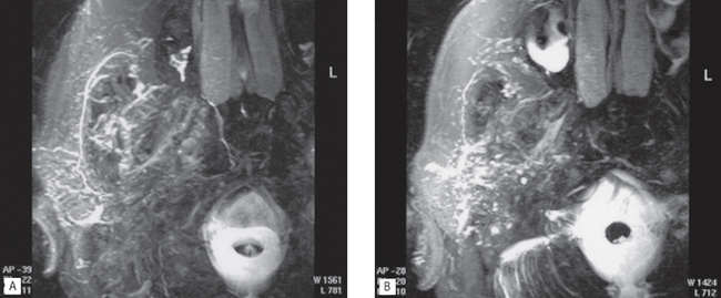
In addition, sialography may also be performed using advanced imaging modalities, e.g. CT sialography and MR sialography (see Fig. 33.20).
Sialographic interpretation
Once again, the essential requirements include:
• A detailed knowledge of the radiographic appearances of normal salivary glands
• A detailed knowledge of the pathological conditions affecting the salivary glands.
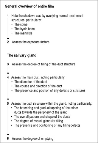
Systematic approach
A suggested systematic approach for viewing sialographs is shown in Figure 33.3.
Normal sialographic appearances of the parotid gland
• The main duct is of even diameter (1–2 mm wide) and should be filled completely and uniformly.
• The duct structure within the gland branches regularly and tapers gradually towards the periphery of the gland, the so-called tree in winter appearance (see Fig. 33.4).
Normal sialographic appearances of the submandibular gland
• The main duct is of even diameter (3–4 mm wide) and should be filled completely and uniformly
• This gland is smaller than the parotid, but the overall appearance is similar with the branching duct structure tapering gradually towards the periphery — the so-called bush in winter appearance (see Fig. 33.5).
Pathological appearances
Based on the suggested systematic approach to sialographic assessment, the main pathological changes can be divided into:
Sialographic appearances of calculi include:
• Filling defect(s) in the main duct
• Ductal dilatation proximal to the calculus
• The emptying film usually shows contrast medium retained behind the s0tone.
See Figures 33.6-33.8.
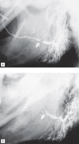
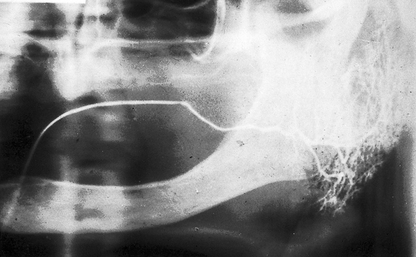
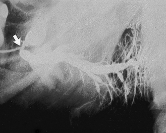
Fig. 33.6 A Sialograph of a left parotid gland showing a filling defect at the posterior end of the main duct (arrowed), caused by a stone in the duct. Ductal dilatation is evident beyond the stone. B Emptying film of the same gland showing the contrast medium retained behind the filling defect (arrowed), confirming the diagnosis of salivary calculus in the main duct.
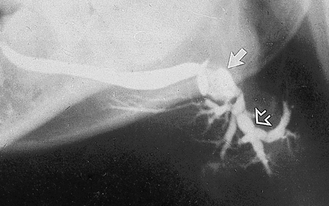
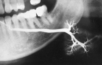
Fig. 33.7 Sialograph of a left submandibular gland, showing a normal main duct, a large calculus (solid arrow) at the posterior end of the main duct and associated segmental sacculation or dilatation and stricture of the ducts beyond the stone. Within the gland (open arrow) the sausage-link appearance is caused by sialodochitis.
Sialographic appearances of sialodochitis include:
• Segmented sacculation or dilatation and stricture of the main duct, the so-called sausage link appearance
See Figures 33.7 and 33.8.
Sialographic appearances of sialadenitis include:
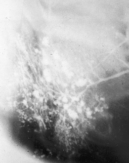
• Dots or blobs of contrast medium within the gland, an appearance known as sialectasis (see Fig. 33.9) caused by the inflammation of the glandular tissue producing saccular dilatation of the acini
Sialographic appearances in Sjögren’s syndrome include:
• Widespread dots or blobs of contrast medium within the gland, an appearance known as punctate sialectasis or snowstorm (see Fig. 33.10). This is caused by a weakening of the epithelium lining the intercalated ducts, allowing the escape of the contrast medium out of the ducts
• Considerable retention of the contrast medium during the emptying phase
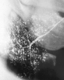
Fig. 33.10 Sialograph of a right parotid gland of a patient with Sjögren’s syndrome. The main duct is normal and there are widespread dots or blobs of contrast medium throughout the gland, the snowstorm appearance of punctate sialectasis.
An understanding of the underlying disease processes explains why the sialographic appearances of sialadenitis and Sjögren’s syndrome (two totally different conditions) are so similar. This is shown diagrammatically in Figure 33.11.
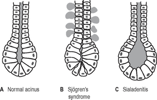
Fig. 33.11 Diagrams showing an intercalated ductule and acinus. A In a normal gland. B In Sjögren’s syndrome, the epithelium lining the intercalated ductule becomes weakened allowing escape of the contrast medium out of the duct so producing the dots or blobs. C In sialadenitis, the acinus becomes dilated allowing the collection of contrast into a dot or blob.
Sialographic appearances of intrinsic tumours include:
• An area of underfilling within the gland, owing to ductal compression by the tumour
• Ductal displacement — the ducts adjacent to the tumour are usually stretched around it, an appearance known as ball in hand (see Figs 33.12 and 33.13)
• Retention of contrast medium in the displaced ducts during the emptying phase.
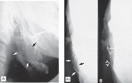
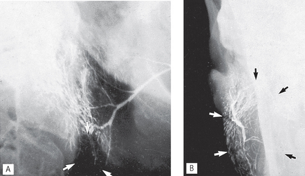
Fig. 33.12 A(i) Sialograph of a right parotid showing a large area of underfilling in the lower lobe (arrowed) caused by an intrinsic tumour (biopsy confirmed a pleomorphic adenoma). A(ii) Rotated AP view showing the lateral bowing and displacement of the ducts (arrowed) around the tumour. B Rotated AP view of a normal parotid gland for comparison.
Interventional sialography
Conventional sialographic techniques can be supplemented and expanded into minimally invasive interventional procedures by using balloon catheters and small Dormia baskets under fluoroscopic guidance. The balloon catheter, as the name implies, can be inflated once positioned within a duct to produce dilatation of ductal strictures. The Dormia basket may be used to retrieve mobile ductal salivary stones (see Fig. 33.14). Both these procedures are now being used successfully to relieve salivary gland obstruction without the need for surgery.
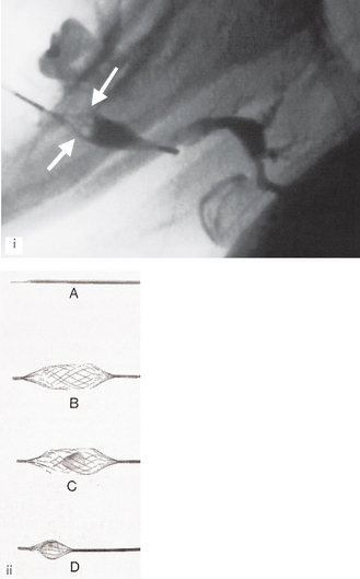
Fig. 33.14 (i) Fluoroscopic sialograph showing an open Dormia basket in the left submandbular duct. The stone has been captured and is inside the basket (white arrows). Contract media is evident in the dilated main duct within the gland. (ii) The Meditech (Boston Scientific) Dormia basket – A closed for insertion beyond the stone; B open ready to draw back; C open with the stone inside and D closed around the stone ready for withdrawal.
(Kindly provided by Mrs J.E.Brown.)
Ultrasound
Ultrasound imaging of the salivary glands as shown in Figure 33.15 is becoming increasingly common. Modern high resolution scanners produce excellent images and that coupled with the numerous advantages shown below has elevated ultrasound to the imaging modality of choice for many patients with salivary gland disorders as shown in Figures 33.16-33.18.
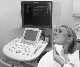
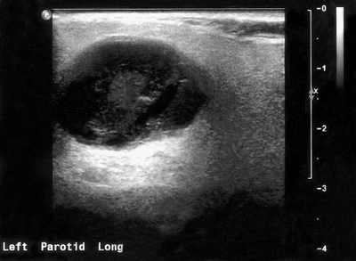
Fig. 33.16 Ultrasound image of a pleomorphic adenoma in the parotid gland. The benign tumour shows well defined margins and is generally hypoechoic (dark) with through transmission suggesting low density and a high water content.
(Kindly provided by Mrs J.E. Brown.)
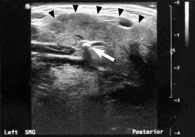
Fig. 33.17 Ultrasound image of a submandibular gland (the margin of the gland is marked by the black arrow heads) containing a small calculus (white arrow) within the hilum of the main duct. The stone measured 2.2 mm in diameter and was radiolucent on plain radiography. The dilated duct to the right of the stone is also evident.
(Kindly provided by Mrs J.E. Brown.)
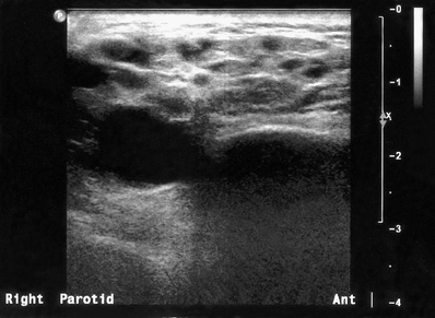
Fig. 33.18 Ultrasound image showing the changes typically seen within the parotid gland in Sjögren’s syndrome. The multiple small hypoechoic (dark) areas represent lymphoepithelial infiltration of the gland parenchyma.
(Kindly provided by Mrs J.E. Brown.)
Advantages
• Ionizing radiation is not used
• Provides good imaging of superficial masses
• Useful for differentiating between solid and cystic masses and for identifying the nature and location of the margins of a lesion
• Different echo signals from different tumours
• Assessment of blood flow using colour Doppler
• Identification of radiolucent stones
• Lithotripsy of salivary stones
• Ultrasound-guided fine-needle aspiration (FNA) biopsy possible
Magnetic resonance (MR)
Advantages
• Ionizing radiation is not used
• Provides excellent soft tissue detail, readily enables differentiation between normal and abnormal
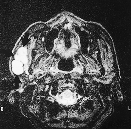
• Provides accurate localization of masses (see Fig. 33.19) and may be able to distinguish benign from malignant tumours
• The facial nerve may be identifiable
• Images in all planes are available
• Co-localization possible with PET scans
• MR sialography may be performed (see Fig. 33.20) together with MR spectroscopy
• Water in the ducts and glands can be visualized to create MR sialographs without the use of contrast agents (see Fig. 33.20)
• MR spectroscopy can be performed to differentiate different tissues by their chemical constituents.
Radioisotope imaging
Advantages
• Provides an indication of salivary gland function (see Fig. 33.21)
• Allows bilateral comparison and images all four major salivary glands at the same time
• Computer analysis of results is possible
• Can be performed in cases of acute infection
• Co-localization of PET with CT or MR scans (see Ch. 19).
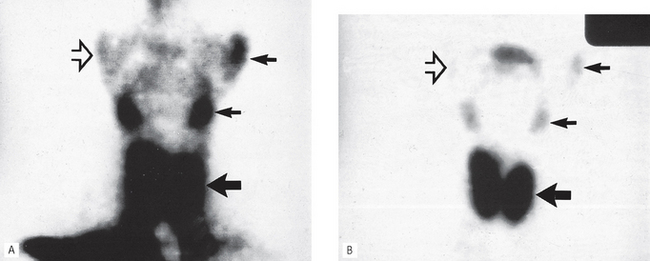
Fig. 33.21 Two radioisotope scans showing the thyroid (large arrow) and salivary glands (small arrows). A 2 minutes after the injection of technetium. B 15 minutes after the injection of technetium. In the 2-minute image, note the large amount of background activity owing to the technetium still in the bloodstream and in both scans the lack of uptake by the non-functioning RIGHT parotid (open arrow).
Flow-rate studies
These are used to investigate salivary gland function. Comparative flow rates of saliva from the major salivary glands are measured over a time period.
Computed tomography (CT)
Advantages
Disadvantages
• Provides no indication of salivary gland function
• Risks associated with intravenous contrast media if used (see Ch. 19)
• Fine duct detail is not well imaged
• May be difficult to distinguish tumours in the submandibular gland from normal gland tissue (due to similar density).