Electricity, Magnetism, and Electromagnetism
At the completion of this chapter, the student should be able to do the following:
1 Define electrification and provide examples.
2 List the laws of electrostatics.
3 Identify units of electric current, electric potential, and electric power.
4 Identify the interactions between matter and magnetic fields.
5 Discuss the four laws of magnetism.
6 Relate the experiments of Oersted, Lenz, and Faraday in defining the relationships between electricity and magnetism.
THIS CHAPTER on electricity, magnetism, and electromagnetism briefly introduces the basic concepts needed for further study of the x-ray imaging system and its various components.
Because the primary function of the x-ray imaging system is to convert electric energy into electromagnetic energy—x-rays—the study of electricity, magnetism, and electromagnetism is particularly important.
This chapter begins by introducing some examples of familiar devices that convert electricity into other forms of energy. Electrostatics is the science of stationary electric charges. Electrodynamics is the science of electric charges in motion. Electromagnetism describes how electrons are given electric potential energy (voltage) and how electrons in motion create magnetism.
Magnetism has become increasingly important in diagnostic imaging with the application of magnetic resonance imaging (MRI) as a medical diagnostic tool. This chapter describes the nature of magnetism by discussing the laws that govern magnetic fields. These laws are similar to those that govern electric fields; knowing them is essential to understanding the function of several components of the x-ray imaging system. Electromagnetic induction is a means of transferring electric potential energy from one position to another, as in a transformer.
The primary function of an x-ray imaging system (Figure 4-1) is to convert electric energy into electromagnetic energy. Electric energy is supplied to the x-ray imaging system in the form of well-controlled electric current. A conversion takes place in the x-ray tube, where most of this electric energy is transformed into heat, some of it into x-rays.
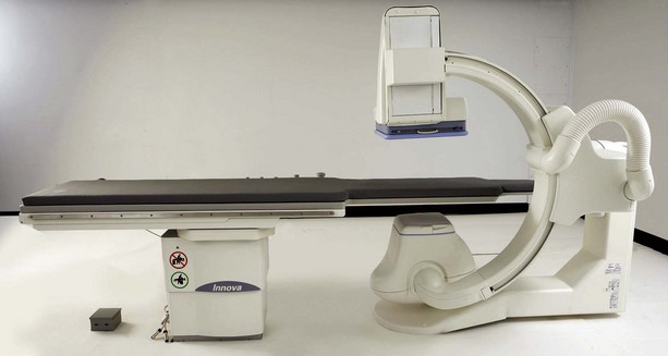
FIGURE 4-1 The x-ray imaging system converts electrical energy into electromagnetic energy. (Courtesy GE Healthcare.)
Figure 4-2 shows other, more familiar examples of electric energy conversion. When an automobile battery runs down, an electric charge restores the chemical energy of the battery. Electric energy is converted into mechanical energy with a device known as an electric motor, which can be used to drive a circular saw. A kitchen toaster or electric range converts electric energy into thermal energy. There are, of course, many other examples of converting electric energy into other forms of energy.
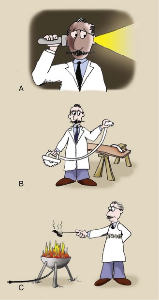
FIGURE 4-2 Electric energy can be converted from or to other forms by various devices, such as the battery (A) from chemical energy, the motor (B) to mechanical energy, and the barbecue (C) to thermal energy.
Electrostatics
Electric charge comes in discrete units that are positive or negative. Electrons and protons are the smallest units of electric charge. The electron has one unit of negative charge; the proton has one unit of positive charge. Thus, the electric charges associated with an electron and a proton have the same magnitude but opposite signs.
Because of the way atoms are constructed, electrons often are free to travel from the outermost shell of one atom to another atom. Protons, on the other hand, are fixed inside the nucleus of an atom and are not free to move. Consequently, nearly all discussions of electric charge deal with negative electric charges—that associated with the electron.
On touching a metal doorknob after having walked across a deep-pile carpet in winter, you get a shock (by contact). Such a shock occurs because electrons are rubbed off the carpet onto your shoes (by friction), causing you to become electrified. An object is said to be electrified if it has too few or too many electrons.
However, the outer shell electrons of some types of atoms are loosely bound and can be removed easily. Removal of these electrons electrifies the substances from which they were removed and results in static electricity.
If you run a comb through your hair, electrons are removed from the hair and deposited on the comb. The comb becomes electrified with too many negative charges. An electrified comb can pick up tiny pieces of paper as though the comb were a magnet (Figure 4-3). Because of its excess electrons, the comb repels some electrons in the paper, causing the closest end of the paper to become slightly positively charged. This results in a small electrostatic attractive force. Similarly, hair is electrified because it has an abnormally low number of electrons and may stand on end because of mutual repulsion.
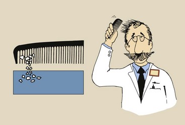
FIGURE 4-3 Running a comb briskly through your hair may cause both your hair and the comb to become electrified through the transfer of electrons from hair to comb. The electrified condition may make it possible to pick up small pieces of paper with the comb and may cause one’s hair to stand on end.
One object that is always available to accept electric charges from an electrified object is the Earth. The Earth behaves as a huge reservoir for stray electric charges. In this capacity, it is called an electric ground.
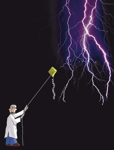
During a thunderstorm, wind and cloud movement can remove electrons from one cloud and deposit them on another (by induction). Both such clouds become electrified, one negatively and one positively.
If the electrification becomes sufficiently intense, a discharge can occur between the clouds; in this case, electrons are rapidly transported back to the cloud that is deficient. This phenomenon is called lightning. Although lightning can occur between clouds, it most frequently occurs between an electrified cloud and the Earth (Figure 4-4).
Another familiar example of electrification is seen in every Frankenstein movie. Usually, Dr. Frankenstein’s laboratory is filled with electric gadgets, wire, and large steel balls with sparks flying in every direction (Figure 4-5). These sparks are created because the various objects—wires, steel balls, and so forth—are highly electrified.
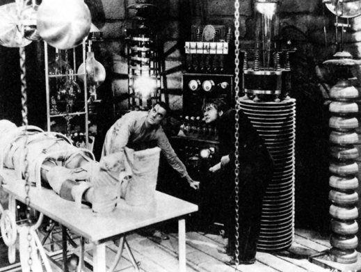
FIGURE 4-5 Early radiologic technologists are shown in this scene from the original Frankenstein movie (1931). (Courtesy Bettmann/Corbis.)
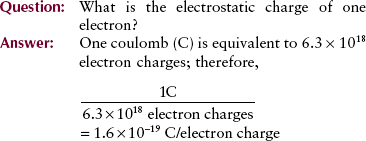
The smallest unit of electric charge is the electron. This charge is much too small to be useful, so the fundamental unit of electric charge is the coulomb (C): 1 C = 6.3 × 10¹⁸ electron charges.
| Question: | The electrostatic charge transferred between two people after one has scuffed his feet across a nylon rug is one microcoulomb. How many electrons are transferred? |
| Answer: | 1 C = 6 × 10¹⁸ electrons 1 µC = 6 × 10¹² electrons transferred |
Electrostatic Laws
Four general laws of electrostatics describe how electric charges interact with each other and with neutral objects.
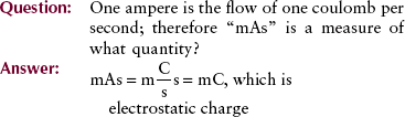
Associated with each electric charge is an electric field. The electric field points outward from a positive charge and toward a negative charge. Uncharged particles do not have an electric field. In Figure 4-6, lines associated with each charged particle illustrate the intensity of the electric field.
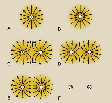
FIGURE 4-6 Electric fields radiate out from a positive charge (A) and toward a negative charge (B). Like charges repel one another (C and D). Unlike charges attract one another (E). Uncharged particles do not have an electric field (F).
When two similar electric charges—negative and negative or positive and positive—are brought close together, their electric fields are in opposite directions, which cause the electric charges to repel each other.
When unlike charges—one negative and one positive—are close to each other, the electric fields radiate in the same direction and cause the two charges to attract each other. The force of attraction between unlike charges or repulsion between like charges is attributable to the electric field. It is called an electrostatic force.
Coulomb’s Law
The magnitude of the electrostatic force is given by Coulomb’s law as follows:
 Coulomb’s Law

where F is the electrostatic force (newton), QA and QB are electrostatic charges (coulomb), d is the distance between the charges (meter), and k is a constant of proportionality.
 Coulomb’s law: The electrostatic force is directly proportional to the product of the electrostatic charges and inversely proportional to the square of the distance between them.
The electrostatic force is very strong when objects are close but decreases rapidly as objects separate. This inverse square relationship for electrostatic force is the same as that for x-ray intensity (see Chapter 3).
When a diffuse nonconductor such as a thunder cloud becomes electrified, the electric charges are distributed rather uniformly throughout. With electrified copper wire, excess electrons are distributed on the outer surface (Figure 4-7).
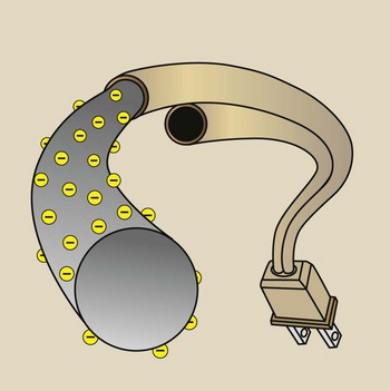
FIGURE 4-7 Cross section of an electrified copper wire, showing that the surface of the wire has excessive electrostatic charges.
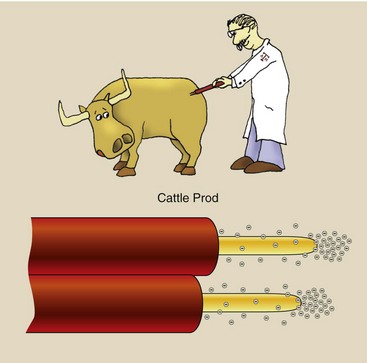
With an electrified cattle prod (Figure 4-8), electric charges are equally distributed on the surface of the two electrodes, except at each tip, where electric charge is concentrated. “Our business is shocking” is the motto of the manufacturer of the leading cattle prod.
Electric Potential
The discussion of potential energy in Chapter 1 emphasized the relationship of such energy to work. A system that possesses potential energy is a system with stored energy. Such a system has the ability to do work when this energy is released.
Electric charges have potential energy. When positioned close to each other, like electric charges have electric potential energy because they can do work when they fly apart. Electrons bunched up at one end of a wire create an electric potential because the electrostatic repulsive force causes some electrons to move along the wire so that work can be done.
Electric potential is sometimes called voltage; the higher the voltage, the greater is the potential to do work. In the United States, the electric potential in homes and offices is 110 V. X-ray imaging systems usually require 220 V or higher. The volt is potential energy/unit charge, or joule/coulomb (1 V = 1 J/C).
Electrodynamics
We recognized electrodynamic phenomena as electricity. If an electric potential is applied to objects such as copper wire, then electrons move along the wire. This is called an electric current, or electricity.
Electric currents occur in many types of objects and range from the very small currents of the human body (e.g., those measured by electrocardiograms) to the very large currents of 440,000-V cross-country electric transmission lines.
The direction of electric current is important. In his early classic experiments, Benjamin Franklin assumed that positive electric charges were conducted on his kite string. The unfortunate result is the convention that the direction of electric current is always opposite that of electron flow. Whereas electrical engineers work with electric current, physicists are usually concerned with electron flow.
A section of conventional household electric wire consists of a metal conducting wire, usually copper, coated with a rubber or plastic insulating material. The insulator confines the electron flow to the conductor. Touching the insulator does not result in a shock; touching the conductor does.
Most metals are good electric conductors; copper is one of the best. Water is also a good electric conductor because of the salts and other impurities it contains. That is why everyone should avoid water when operating power tools. Glass, clay, and other earthlike materials are usually good electric insulators.
Other materials exhibit two entirely different electric characteristics. In 1946, William Shockley demonstrated semiconduction. The principal semiconductor materials are silicon (Si) and germanium (Ge). This development led to microchips and hence the explosive rise of computer technology.
A semiconductor is a material that under some conditions behaves as an insulator and in other conditions behaves as a conductor.
At room temperature, all materials resist the flow of electricity. Resistance decreases as the temperature of material is reduced (Figure 4-9). Superconductivity is the property of some materials to exhibit no resistance below a critical temperature (Tc).
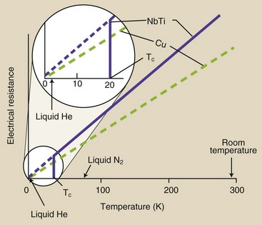
FIGURE 4-9 The electrical resistance of a conductor (Cu) and a superconductor (NbTi) as a function of temperature.
Superconductivity was discovered in 1911 but was not developed commercially until the early 1960s. Scientific investigation into superconductivity has grown in recent years and now focuses on high-temperature superconductivity (Figure 4-10).
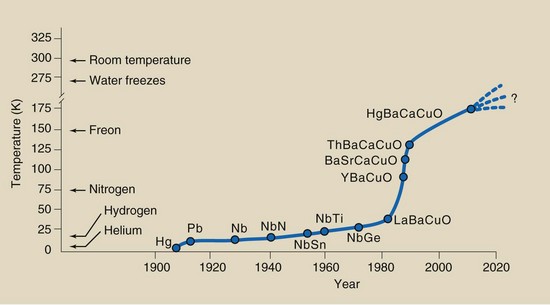
FIGURE 4-10 Recent years have seen a dramatic rise in the critical temperature for superconducting materials.
Superconducting materials such as niobium and titanium allow electrons to flow without resistance. Ohm’s law, described in the next section, does not hold true for superconductors. A superconducting circuit can be viewed as one in perpetual motion because electric current exists without voltage. For material to behave as a superconductor, however, it must be made very cold, which requires energy.
Table 4-1 summarizes the four electric states of matter.
TABLE 4-1
Four Electric States of Matter
| State | Material | Characteristics |
| Superconductor | Niobium | No resistance to electron flow |
| Titanium | No electric potential require | |
| Must be very cold | ||
| Conductor | Copper | Variable resistance |
| Aluminum | Obeys Ohm’s law | |
| Requires a voltage | ||
| Semiconductor | Silicon | Can be conductive |
| Germanium | Can be resistive | |
| Basis for computers | ||
| Insulator | Rubber | Does not permit electron flow |
| Glass | Extremely high resistance | |
| Necessary with high voltage |
Electric Circuits
Modifying a conducting wire by reducing its diameter (wire gauge) or inserting different material (circuit elements) can increase its resistance. When this resistance is controlled and the conductor is made into a closed path, the result is an electric circuit.
Electric current is measured in amperes (A). The ampere is proportional to the number of electrons flowing in the electric circuit. One ampere is equal to an electric charge of 1 C flowing through a conductor each second.
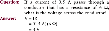
Electric potential is measured in volts (V), and electric resistance is measured in ohms (Ω). Electrons at high voltage have high potential energy and high capacity to do work. If electron flow is inhibited, the circuit resistance is high.
The manner in which electric currents behave in an electric circuit is described by a relationship known as Ohm’s law.
Ohm’s law: The voltage across the total circuit or any portion of the circuit is equal to the current times the resistance.
Ohm’s Law

where V is the electric potential in volts, I is the electric current in amperes, and R is the electric resistance in ohms. Variations of this relationship are expressed as follows:


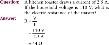
Most electric circuits, such as those used in radios, televisions, and other electronic devices, are very complicated. X-ray circuits are also complicated and contain a number of different types of circuit elements. Table 4-2 identifies some of the important types of circuit elements, the functions of each, and their symbols.
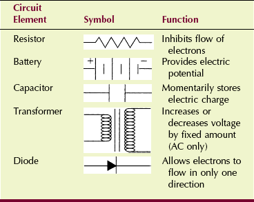
Usually, electric circuits can be reduced to one of two basic types: a series circuit (Figure 4-11) or a parallel circuit (Figure 4-12).
Rules for Series Circuits
The total resistance is equal to the sum of the individual resistances.
The current through each circuit element is the same and is equal to the total circuit current.
The sum of the voltages across each circuit element is equal to the total circuit voltage.
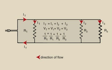
A parallel circuit contains elements that are connected at their ends rather than lying in a line along a conductor.
Rules for a Parallel Circuit
The sum of the currents through each circuit element is equal to the total circuit current.
The voltage across each circuit element is the same and is equal to the total circuit voltage.
The total resistance is the inverse of the sum of the reciprocals of each individual resistance.
Christmas lights are a good example of the difference between series and parallel circuits. Christmas lights wired in series have only one wire that connects each lamp; when one lamp burns out, the entire string of lights goes out. Christmas lights wired in parallel, on the other hand, have two wires that connect each lamp; when one lamp burns out, the rest remain lit.
Electric current, or electricity, is the flow of electrons through a conductor. These electrons can be made to flow in one direction along the conductor, in which case the electric current is called direct current (DC).
Most applications of electricity require that the electrons be controlled so that they flow first in one direction and then in the opposite direction. Current in which electrons oscillate back and forth is called alternating current (AC).
Electrons that flow in only one direction constitute DC; electrons that flow alternately in opposite directions constitute AC.
Figure 4-13 diagrams the phenomenon of DC and shows how it can be described by a graph called a waveform. The horizontal axis, or x-axis, of the current waveform represents time; the vertical axis, or y-axis, represents the amplitude of the electric current. For DC, the electrons always flow in the same direction; therefore, DC is represented by a horizontal line. The vertical separation between this line and the time axis represents the magnitude of the current or the voltage.
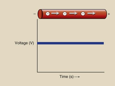
FIGURE 4-13 Representation of direct current. Electrons flow in one direction only. The graph of the associated electric waveform is a straight line.
The waveform for AC is a sine curve (Figure 4-14). Electrons flow first in a positive direction and then in a negative direction. At one instant in time (point 0 in Figure 4-14), all electrons are at rest. Then they move, first in the positive direction with increasing potential (segment A).
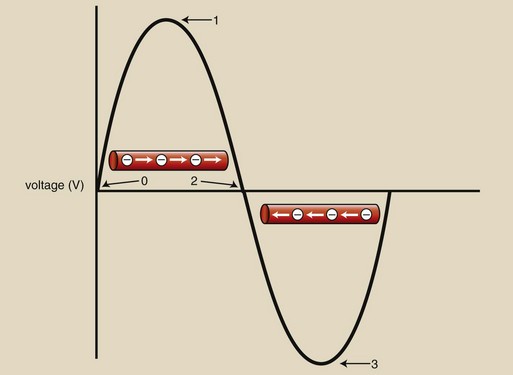
FIGURE 4-14 Representation of alternating current. Electrons flow alternately in one direction and then the other. Alternating current is represented graphically by a sinusoidal electric waveform.
When they reach maximum flow number, represented by the vertical distance from the time axis (point 1), the electric potential is reduced (segment B). They come to zero again momentarily (point 2) and then reverse motion and flow in the negative direction (segment C), increasing in negative electric potential to maximum (point 3). Next, the electric potential is reduced to zero (segment D).
This oscillation in electron direction occurs sinusoidally, with each requiring  s. Consequently, AC is identified as a 60-Hz current (50 Hz in Europe and in much of the rest of the world).
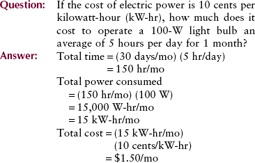
Electric Power
Electric power is measured in watts (W). Common household electric appliances, such as toasters, blenders, mixers, and radios, generally require 500 to 1500 W of electric power. Light bulbs require 30 to 150 W of electric power. An x-ray imaging system requires 20 to 150 kW of electric power.
One watt is equal to 1 A of current flowing through an electric potential of 1 V. Power (W) = voltage (V) × current (A).
Electric Power

where P is the power in watts, I is the current in amperes, and V is the electric potential in volts; alternatively,


Magnetism
Around 1000 bc, shepherds and dairy farmers near the village of Magnesia (what is now Western Turkey) discovered magnetite, an oxide of iron (Fe3O4). This rodlike stone, when suspended by a string, would rotate back and forth; when it came to rest, it pointed the way to water. It was called a lodestone or leading stone.
Of course, if you walk toward the North Pole from any spot on Earth, you will find water. So, the word magnetism comes from the name of that ancient village where the cows too were very curious. When milked, they produced Milk of Magnesia!
Magnetism is a fundamental property of some forms of matter. Ancient observers knew that lodestones would attract iron filings. They also knew that rubbing an amber rod with fur caused it to attract small, lightweight objects such as paper. They considered these phenomena to be different. We know them as magnetism and electrostatics, respectively; both are manifestations of the electromagnetic force.
Magnetism is perhaps more difficult to understand than other characteristic properties of matter, such as mass, energy, and electric charge, because magnetism is difficult to detect and measure. We can feel mass, visualize energy, and be shocked by electricity, but we cannot sense magnetism.
The magnetic field of a charged particle such as an electron in motion is perpendicular to the motion of that particle. The intensity of the magnetic field is represented by imaginary lines (Figure 4-15).
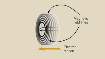
FIGURE 4-15 A moving charged particle induces a magnetic field in a plane perpendicular to its motion.
If the electron’s motion is a closed loop, as with an electron circling a nucleus, magnetic field lines will be perpendicular to the plane of motion (Figure 4-16).
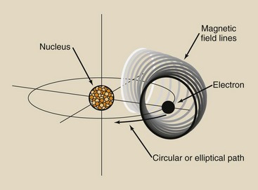
FIGURE 4-16 When a charged particle moves in a circular or elliptical path, the perpendicular magnetic field moves with the charged particle.
Electrons behave as if they rotate on an axis clockwise or counterclockwise. This rotation creates a property called electron spin. The electron spin creates a magnetic field, which is neutralized in electron pairs. Therefore, atoms that have an odd number of electrons in any shell exhibit a very small magnetic field.
Spinning electric charges also induce a magnetic field (Figure 4-17). The proton in a hydrogen nucleus spins on its axis and creates a nuclear magnetic dipole called a magnetic moment. This forms the basis of MRI.
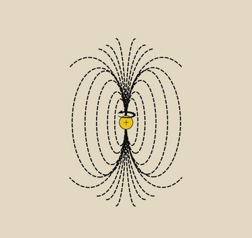
The lines of a magnetic field do not start or end as the lines of an electric field do. Such a field is called bipolar or dipolar; it always has a north and a south pole. The small magnet created by the electron orbit is called a magnetic dipole.
An accumulation of many atomic magnets with their dipoles aligned creates a magnetic domain. If all the magnetic domains in an object are aligned, it acts like a magnet. Under normal circumstances, magnetic domains are randomly distributed (Figure 4-18, A).
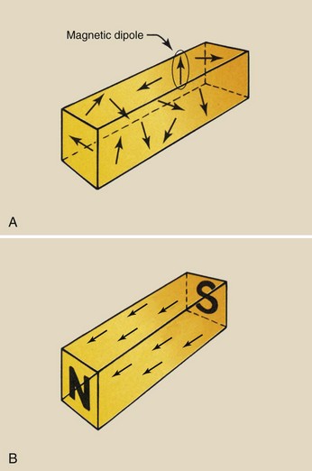
FIGURE 4-18 A, In ferromagnetic material, the magnetic dipoles are randomly oriented. B, This changes when the dipoles are brought under the influence of an external magnetic field.
When acted on by an external magnetic field, however, such as the Earth in the case of naturally occurring ores or an electromagnet in the case of artificially induced magnetism, randomly oriented dipoles align with the magnetic field (see Figure 4-18, B). This is what happens when ferromagnetic material is made into a permanent magnet.
The magnetic dipoles in a bar magnet can be thought of as generating imaginary lines of the magnetic field (Figure 4-19). If a nonmagnetic material is brought near such a magnet, these field lines are not disturbed. However, if ferromagnetic material such as soft iron is brought near the bar magnet, the magnetic field lines deviate and are concentrated into the ferromagnetic material.
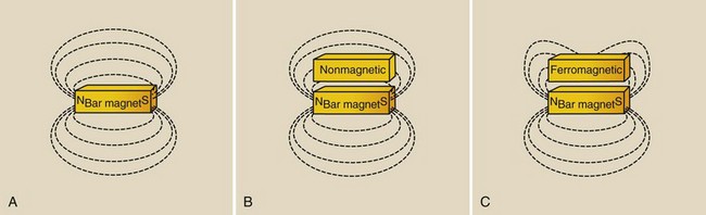
FIGURE 4-19 A, Imaginary lines of force. B, These lines of force are undisturbed by nonmagnetic material. C, They are deviated by ferromagnetic material.
Magnetic permeability is the ability of a material to attract the lines of magnetic field intensity.
There are three principal types of magnets: naturally occurring magnets, artificially induced permanent magnets, and electromagnets.
The best example of a natural magnet is the Earth itself. The Earth has a magnetic field because it spins on an axis. Lodestones in the Earth exhibit strong magnetism presumably because they have remained undisturbed for a long time within the Earth’s magnetic field.
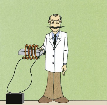
Artificially produced permanent magnets are available in many sizes and shapes but principally as bar or horseshoe-shaped magnets, usually made of iron. A compass is a prime example of an artificial permanent magnet. Permanent magnets are typically produced by aligning their domains in the field of an electromagnet (Figure 4-20).
Such permanent magnets do not necessarily stay permanent. One can destroy the magnetic property of a magnet by heating it or even by hitting it with a hammer. Either act causes individual magnetic domains to be jarred from their alignment. They thus again become randomly aligned, and magnetism is lost.
Electromagnets consist of wire wrapped around an iron core. When an electric current is conducted through the wire, a magnetic field is created. The intensity of the magnetic field is proportional to the electric current. The iron core greatly increases the intensity of the magnetic field.
All matter can be classified according to the manner in which it interacts with an external magnetic field.
Many materials are unaffected when brought into a magnetic field. Such materials are nonmagnetic and include substances such as wood and glass.
Diamagnetic materials are weakly repelled by either magnetic pole. They cannot be artificially magnetized, and they are not attracted to a magnet. Examples of such diamagnetic materials are water and plastic.
Ferromagnetic materials include iron, cobalt, and nickel. These are strongly attracted by a magnet and usually can be permanently magnetized by exposure to a magnetic field. An alloy of aluminum, nickel, and cobalt called alnico is one of the more useful magnets produced from ferromagnetic material. Rare earth ceramics have been developed recently and are considerably stronger magnets (Figure 4-21).
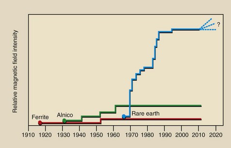
FIGURE 4-21 Developments in permanent magnet design have resulted in a great increase in magnetic field intensity.
Paramagnetic materials lie somewhere between ferromagnetic and nonmagnetic. They are very slightly attracted to a magnet and are loosely influenced by an external magnetic field. Contrast agents used in MRI are paramagnetic.
When wood is placed in a strong magnetic field, it does not increase the strength of the field: Wood has low magnetic susceptibility. On the other hand, when iron is placed in a magnetic field, it greatly increases the strength of the field: Iron has high magnetic susceptibility.
This phenomenon is used in transformers when the core of the transformer greatly enhances its efficiency. These four magnetic states of matter are summarized in Table 4-3.
TABLE 4-3
Four Magnetic States of Matter
| State | Material | Characteristics |
| Nonmagnetic | Wood, glass | Unaffected by a magnetic field |
| Diamagnetic | Water, plastic | Weakly repelled from both poles of a magnetic field |
| Paramagnetic | Gadolinium | Weakly attracted to both poles of a magnetic field |
| Ferromagnetic | Iron, nickel, cobalt | Can be strongly magnetized |
Magnetic Laws
The physical laws of magnetism are similar to those of electrostatics and gravity. The forces associated with these three fields are fundamental.
The equations of force and the fields through which they act have the same form. Much work in theoretical physics involves the attempt to combine these fundamental forces with two others—the strong nuclear force and the weak interaction—to formulate a grand unified field theory.
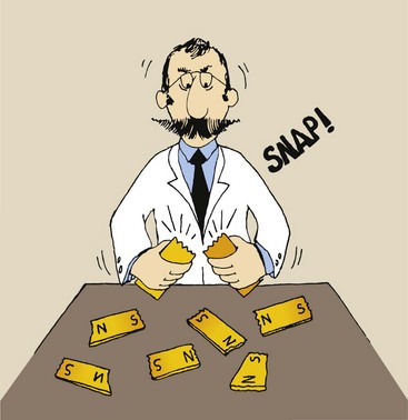
In contrast to the case with electricity, there is no smallest unit of magnetism. Dividing a magnet simply creates two smaller magnets, which when divided again and again make baby magnets (Figure 4-22).
How do we know that these imaginary lines of the magnetic field exist? They can be demonstrated by the action of iron filings near a magnet (Figure 4-23).
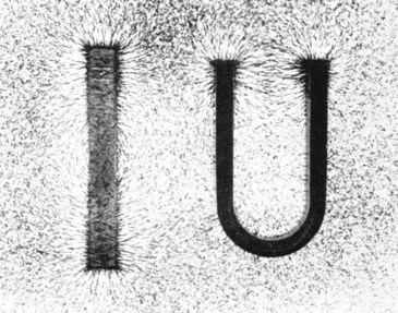
If a magnet is placed on a surface with small iron filings, the filings attach most strongly and with greater concentration to the ends of the magnet. These ends are called poles, and every magnet has two poles, a north pole and a south pole, analogous to positive and negative electrostatic charges.
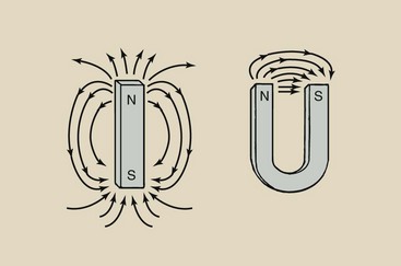
As with electric charges, like magnetic poles repel, and unlike magnetic poles attract. Also by convention, the imaginary lines of the magnetic field leave the north pole of a magnet and return to the south pole (Figure 4-24).
Magnetic Induction
Just as an electrostatic charge can be induced from one material to another, so some materials can be made magnetic by induction. The imaginary magnetic field lines just described are called magnetic lines of induction, and the density of these lines is proportional to the intensity of the magnetic field.
When ferromagnetic material, such as a piece of soft iron, is brought into the vicinity of an intense magnetic field, the lines of induction are altered by attraction to the soft iron, and the iron is made temporarily magnetic (Figure 4-25). If copper, a diamagnetic material, were to replace the soft iron, there would be no such effect.
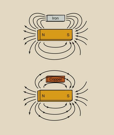
FIGURE 4-25 Ferromagnetic material such as iron attracts magnetic lines of induction, whereas nonmagnetic material such as copper does not.
This principle is used with many MRI systems that use an iron magnetic shield to reduce the level of the fringe magnetic field. Ferromagnetic material acts as a magnetic sink by drawing the lines of the magnetic field into it.
When ferromagnetic material is removed from the magnetic field, it usually does not retain its strong magnetic property. Soft iron, therefore, makes an excellent temporary magnet. It is a magnet only while its magnetism is being induced. If properly tempered by heat or exposed to an external field for a long period, however, some ferromagnetic materials retain their magnetism when removed from the external magnetic field and become permanent magnets.
The electric and magnetic forces were joined by Maxwell’s field theory of electromagnetic radiation. The force created by a magnetic field and the force of the electric field behave similarly. This magnetic force is similar to electrostatic and gravitational forces that also are inversely proportional to the square of the distance between the objects under consideration. If the distance between two bar magnets is halved, the magnetic force increases by four times.
The magnetic force is proportional to the product of the magnetic pole strengths divided by the square of the distance between them.
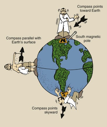
The Earth behaves as though it has a large bar magnet embedded in it. The polar convention of magnetism actually has its origin in the compass. At the equator, the north pole of a compass seeks the Earth’s North Pole (which is actually the Earth’s south magnetic pole).
As one travels toward the North Pole, the attraction of the compass becomes more intense until the compass needle points directly into the Earth, not at the geographic North Pole but at a region in northern Canada—the magnetic pole (Figure 4-26). The magnetic pole in the southern hemisphere is in Antarctica. There, the north end of the compass would point toward the sky.
The SI unit of magnet field strength is the tesla. An older unit is the gauss. One tesla (T) = 10,000 gauss (G).
The use of a compass might suggest that the Earth has a strong magnetic field, but it does not. The Earth’s magnetic field is approximately 50 µT at the equator and 100 µT at the poles. This is far less than the magnet on a cabinet door latch, which is approximately 100 mT, or the magnet of an MRI system, which is 3 T.
Electromagnetism
Until the 19th century, electricity and magnetism were viewed as separate effects. Although many scientists suspected that the two were connected, research was hampered by the lack of any convenient way of producing and controlling electricity.
Thus, the early study of electricity was limited to the investigation of static electricity, which could be produced by friction (e.g., the effect produced by rubbing fur on a rubber rod). Charges could be induced to move but only in a sudden discharge, as with a spark jumping a gap.
The development of methods for producing a steady flow of charges (i.e., an electric current) during the 19th century stimulated investigations of both electricity and magnetism. These investigations led to an enhanced understanding of electromagnetic phenomena and ultimately led to the electronic revolution on which today’s technology is largely based.
In the late 1700s, an Italian anatomist, Luigi Galvani, made an accidental discovery. He observed that a dissected frog leg twitched when touched by two different metals, just as if it had been touched by an electrostatic charge. This prompted Alessandro Volta, an Italian physicist of the same era, to question whether an electric current might be produced when two different metals are brought into contact.
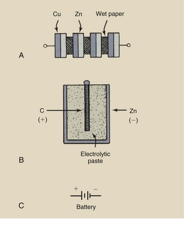
Using zinc and copper plates, Volta succeeded in producing a feeble electric current. To increase the current, he stacked the copper–zinc plates like a Dagwood sandwich to form what was called the Voltaic pile, a precursor of the modern battery. Each zinc-–copper sandwich is called a cell of the battery.
Modern dry cells use a carbon rod as the positive electrode surrounded by an electrolytic paste housed in a negative zinc cylindrical can. Figure 4-27 shows the Voltaic pile, the modern battery, and the electronic symbol for the battery.
These devices are examples of sources of electric potential. Any device that converts some form of energy directly into electric energy is said to be a source of electric potential.
Now that they finally had a source of constant electric current, scientists began extensive investigations into the possibility of a link between electric and magnetic forces. Hans Oersted, a Danish physicist, discovered the first such link in 1820.
Oersted fashioned a long straight wire, supported near a free-rotating magnetic compass (Figure 4-28). With no current in the wire, the magnetic compass pointed north as expected. When a current was passed through the wire, however, the compass needle swung to point straight at the wire. Here we have evidence of a direct link between electric and magnetic phenomena. The electric current evidently produced a magnetic field strong enough to overpower the Earth’s magnetic field and cause the magnetic compass to point toward the wire.
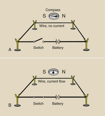
FIGURE 4-28 Oersted’s experiment. A, With no electric current in the wire, the compass points north. B, With electric current, the compass points toward the wire.
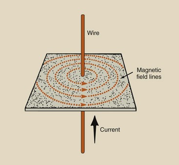
A charge at rest produces no magnetic field. Electrons that flow through a wire produce a magnetic field about that wire. The magnetic field is represented by imaginary lines that form concentric circles centered on the wire (Figure 4-29).
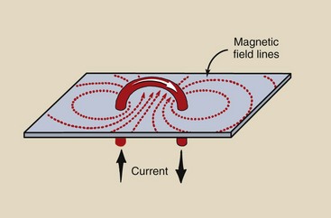
Magnetic field lines form concentric circles around each tiny section of a loop of the wire. Because the wire is curved, however, these magnetic field lines overlap inside the loop. In particular, at the very center of the loop, all of the field lines come together, making the magnetic field strong (Figure 4-30).
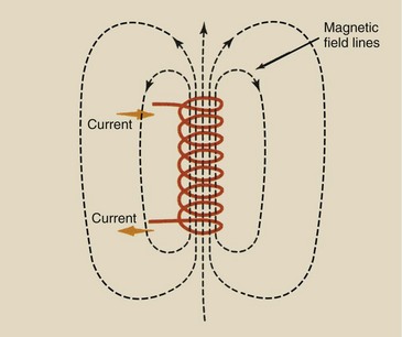
Stacking more loops on top of each other increases the intensity of the magnetic field running through the center or axis of the stack of loops. The magnetic field of a solenoid is concentrated through the center of the coil (Figure 4-31).
The magnetic field can be intensified further by wrapping the coil of wire around ferromagnetic material, such as iron. The iron core intensifies the magnetic field. In this case, almost all of the magnetic field lines are concentrated inside the iron core, escaping only near the ends of the coil. This type of device is called an electromagnet (Figure 4-32).
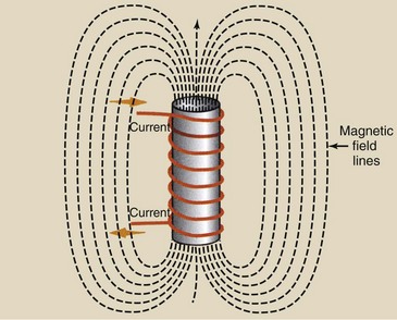
An electromagnet is a current-carrying coil of wire wrapped around an iron core, which intensifies the induced magnetic field.
The magnetic field produced by an electromagnet is the same as that produced by a bar magnet. That is, if both were hidden from view behind a piece of paper, the pattern of magnetic field lines revealed by iron filings sprinkled on the paper surface would be the same. Of course, the advantage of the electromagnet is that its magnetic field can be adjusted by varying the current through its coil of wire.
Electromagnetic Induction
Oersted’s experiment demonstrated that electricity can be used to generate magnetic fields. It is obvious, then, to wonder whether the reverse is true: Can magnetic fields somehow be used to generate electricity? Michael Faraday, a self-educated British experimenter, found the answer to that question.
From a series of experiments, Faraday concluded that an electric current cannot be induced in a circuit merely by the presence of a magnetic field. For example, consider the situation illustrated in Figure 4-33. A coil of wire is connected to a current-measuring device called an ammeter. If a bar magnet were set next to the coil, the meter would indicate no current in the coil.
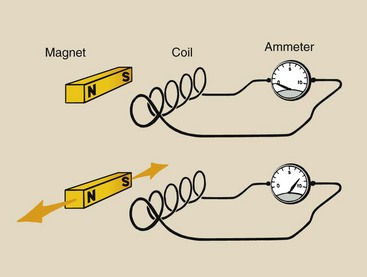
FIGURE 4-33 Schematic description of Faraday’s experiment shows how a moving magnetic field induces an electric current.
However, Faraday discovered that when the magnet is moved, the coiled wire does have a current, as indicated by the ammeter. Therefore, to induce a current with the use of a magnetic field, the magnetic field cannot be constant but must be changing.
Electromagnetic induction: An electric current is induced in a circuit if some part of that circuit is in a changing magnetic field.
This observation is summarized in what is called Faraday’s law.
Actually, no physical motion is needed. An electromagnet can be fixed near a coil of wire. If the current in the electromagnet is then increased or decreased, its magnetic field will likewise change and induce a current in the coil.
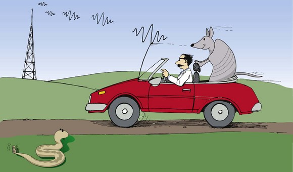
A prime example of electromagnetic induction is radio reception (Figure 4-34). Radio emission consists of waves of electromagnetic radiation. Each wave has an oscillating electric field and an oscillating magnetic field. The oscillating magnetic field induces motion in electrons in the radio antennae, resulting in a radio signal. This signal is detected and decoded to produce sound.
The essential point in all of these examples is that the intensity of the magnetic field at the wire must be changing to induce a current. If the magnetic field intensity is constant, there will be no induced current.
Electromechanical Devices
Electric motors and generators are practical applications of Oersted’s and Faraday’s experiments. In one experiment, an electric current produces a mechanical motion (the motion of the compass needle). This is the basis of the electric motor. In the other experiment, mechanical motion (the motion of a magnet near a coil of wire) induces electricity in a coil of wire. This is the principle on which the electric generator operates.
In an electric generator, a coil of wire is placed in a strong magnetic field between two magnetic poles. The coil is rotated by mechanical energy. The mechanical energy can be supplied by hand, by water flowing over a water wheel, or by steam flowing past the vanes of a turbine blade in a nuclear power plant. Because the coil of wire is moving in the magnetic field, a current is induced in the coil of wire.
The net effect of an electric generator is to convert mechanical energy into electrical energy. The conversion process is, of course, not 100% efficient because of frictional losses in the mechanical moving parts and heat losses caused by resistance in the electrical components.
An electric motor has basically the same components as an electric generator. In this case, however, electric energy is supplied to the current loop to produce a mechanical motion—that is, a rotation of the loop in the magnetic field.
A practical electric motor uses many turns of wire for the current loop and many bar magnets to create the external magnetic field. The principle of operation, however, is the same.
The type of motor used with x-ray tubes is an induction motor (Figure 4-35). In this type of motor, the rotating rotor is a shaft made of bars of copper and soft iron fabricated into one mass; however, the external magnetic field is supplied by several fixed electromagnets called stators.
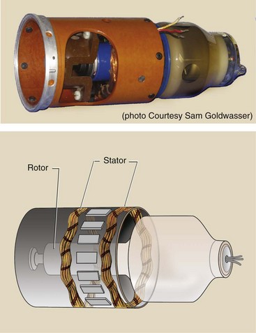
No electric current is passed to the rotor. Instead, current is produced in the rotor windings by induction. The electromagnets surrounding the rotor are energized in sequence, producing a changing magnetic field. The induced current produced in the rotor windings generates a magnetic field.
Just as in a conventional electric motor, this magnetic field attempts to align itself with the magnetic field of the external electromagnets. Because these electromagnets are being energized in sequence, the rotor begins to rotate, trying to bring its magnetic field into alignment.
The result is the same as in a conventional electric motor, that is, the rotor rotates continuously. The difference, however, is that the electrical energy is supplied to the external magnets rather than the rotor.
The Transformer
Another device that uses the interacting magnetic fields produced by changing electric currents is the transformer. However, the transformer does not convert one form of energy to another but rather transforms electric potential and current into higher or lower intensity.
Consider an electromagnet with a ferromagnetic core bent around so that it forms a continuous loop (Figure 4-36). There are no end surfaces from which ferromagnetic field lines can escape. Therefore, the magnetic field tends to be confined to the loop of the magnetic core material.
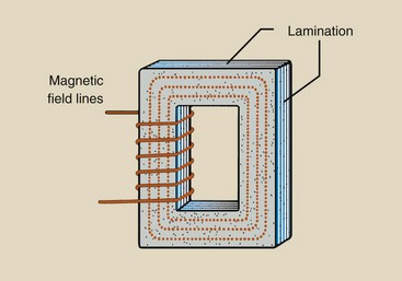
FIGURE 4-36 An electromagnet that incorporates a closed iron core produces a closed magnetic field that is primarily confined to the core.
If a secondary coil is then wound around the other side of this loop of core material, almost all the magnetic field produced by the primary coil also passes through the center of the secondary coil. Thus, there is a good coupling between the magnetic field produced by the primary coil and the secondary coil. A changing current in the primary coil induces a changing current in the secondary coil. This type of device is a transformer.
A transformer will operate only with a changing electric current (AC). A direct current applied to the primary coil will induce no current in the secondary coil.
The transformer is used to change the magnitude of voltage and current in an AC circuit. The change in voltage is directly proportional to the ratio of the number of turns (windings) of the secondary coil (Ns) to the number of turns in the primary coil (Np). If there are 10 turns on the secondary coil for every turn on the primary coil, then the voltage generated in the secondary circuit (Vs) will be 10 times the voltage supplied to the primary circuit (Vp). Mathematically, the transformer law is represented as follows:

The voltage change across the transformer is proportional to the turns ratio. A transformer with a turns ratio greater than 1 is a step-up transformer because the voltage is increased or stepped up from the primary side to the secondary side. When the turns ratio is less than 1, the transformer is a step-down transformer.
As the voltage changes across a transformer, the current (I) changes also; the transformer law may also be written as follows:


The change in current across a transformer is in the opposite direction from the voltage change but in the same proportion: an inverse relationship. For example, if the voltage is doubled, the current is halved.
In a step-up transformer, the current on the secondary side (Is) is smaller than the current on the primary side (Ip). In a step-down transformer, the secondary current is larger than the primary current.
There are many ways to construct a transformer (Figure 4-37). The type of transformer discussed thus far, built about a square core of ferromagnetic material, is called a closed-core transformer (see Figure 4-37, A).
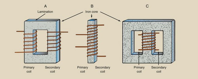
FIGURE 4-37 Type of transformers. A, Closed-core transformer. B, Autotransformer. C, Shell-type transformer.
The ferromagnetic core is not a single piece but rather is built up of laminated layers of iron. This layering helps reduce energy losses, resulting in greater efficiency.
Another type of transformer is the autotransformer (see Figure 4-37, B). It consists of an iron core with only one winding of wire about it. This single winding acts as both the primary and the secondary winding. Connections are made at different points on the coil for both the primary and the secondary sides.
An autotransformer is generally smaller, and because the primary and the secondary sides are connected to the same wire, its use is generally restricted to cases in which only a small step up or step down in voltage is required. Thus, an autotransformer would not be suitable for use as the high-voltage transformer in an x-ray imaging system.
The third type of transformer is the shell-type transformer (see Figure 4-37, C). This type of transformer confines even more of the magnet field lines of the primary winding because the secondary is wrapped around it and there are essentially two closed cores. This type is more efficient than the closed-core transformer. Most currently used transformers are shell type.
The practical applications of the laws of electromagnetism appear in the electric motor (electric current produces mechanical motion), the electric generator (mechanical motion produces electric current), and the transformer (alternating electric current and electric potential are transformed in intensity). The transformer law describes how electric current and voltage change from the primary coil to the secondary coil.
Summary
Electrons can flow from one object to another by contact, by friction, or by induction. The laws of electrostatics are as follows:
Electrostatic force is directly proportional to the product of the charges and inversely proportional to the square of the distance between them. Electric charges are concentrated along the sharpest curvature of the surface of the conductor.
Electrodynamics is the study of electrons in motion, otherwise known as electricity. Conductors are materials through which electrons flow easily. Insulators are materials that inhibit the flow of electrons. Electric current is measured in amperes (A), electric potential is measured in volts (V), and electric resistance is measured in ohms (Ω).
Electric power is energy produced or consumed per unit time. One watt of power is equal to 1 A of electricity flowing through an electric potential of 1 V.
Matter has magnetic properties because some atoms have an odd number of electrons in the outer shells. The unpaired spin of these electrons produces a net magnetic field within the atom. Natural magnets get their magnetism from the Earth, permanent magnets are artificially induced magnets, and electromagnets are produced when current-carrying wire is wrapped around an iron core.
Every magnet, no matter how small, has two poles: north and south. Like magnetic poles repel, and unlike magnetic poles attract. Ferromagnetic material can be made magnetic when placed in an external magnetic field. The force between poles is proportional to the product of the magnetic pole strengths divided by the square of the distance between them.
Alessandro Volta’s development of the battery as a source of electric potential energy prompted additional investigations of electric and magnetic fields. Hans Oersted demonstrated that electricity can be used to generate magnetic fields. Michael Faraday observed the current produced in the presence of a changing magnetic field and described the first law of electromagnetism (Faraday’s law).
Practical applications of the laws of electromagnetism appear in the electric motor (electric current produces mechanical motion), the electric generator (mechanical motion produces electric current), and the transformer (alternating electric current and electric potential are transformed in intensity). The transformer law describes how electric current and voltage change from the primary coil to the secondary coil.
1. Define or otherwise identify the following:
2. What is the total circuit resistance when resistive elements of 5, 10, 15, and 20 Ω are connected in (a) series and (b) parallel?
3. If the total current in the circuit in question 2 is 7 A, what is the voltage across the 10 Ω resistor for (a) series and (b) parallel operation?
4. A radiographic exposure requires 100 mAs. How many electrons is this?
5. Describe three types of transformers.
6. What are the three ways to electrify an object?
7. List the four laws of electrostatics.
8. Why is electrification easier in dry Phoenix than in humid Houston?
9. A mobile x-ray imaging system operates on 110 V AC power. Its maximum capacity is 110 kVp and 100 mA. What is the turns ratio of the high-voltage transformer?
10. What should be the primary current in the previous question to produce a secondary current of 100 mA?
11. Magnetic fields in excess of 5 G can interfere with cardiac pacemakers. How many mT is this?
12. What is the role of magnetism in the study of x-ray imaging?
13. List the three principal types of magnets.
14. Describe an electromagnet.
15. Explain how a magnetic domain can cause an object to behave like a magnet.
16. State Ohm’s how and describe its effect on electric circuits.
17. What happens when a bar magnet is heated to a very high temperature?
18. List three diamagnetic materials.
19. Where in everyday life might one find an electromagnet?
20. What is the range in intensity of the Earth’s magnetic field?
The answers to the Challenge Questions can be found by logging on to our website at http://evolve.elsevier.com.