Essential Concepts of Radiologic Science
At the completion of this chapter, the student should be able to do the following:
1 Describe the characteristics of matter and energy.
2 Identify the various forms of energy.
3 Define electromagnetic radiation and specifically ionizing radiation.
4 State the relative intensity of ionizing radiation from various sources.
5 List the concepts of basic radiation protection.
6 Discuss the derivation of scientific systems of measurement.
THIS CHAPTER explores the basic concepts of the science and technology of x-ray imaging. These include the study of matter, energy, the electromagnetic spectrum, and ionizing radiation. The production and use of ionizing radiation as a diagnostic tool serve as the basis for radiography. Radiologic technologists who deal specifically with x-ray imaging are radiographers. Radiographers have a great responsibility in performing x-ray examinations in accordance with established radiation protection standards for the safety of patients and medical personnel.
The instant an x-ray tube produces x-rays, all of the laws of physics are evident. The projectile electron from the cathode hits the target of the anode producing x-rays. Some x-rays interact with tissue, and other x-rays interact with the image receptor, forming an image. The physics of radiography deals with the production and interaction of x-rays.
Radiography is a career choice with great yet diverse opportunities. Welcome to the field of medical imaging!
Nature of Our Surroundings
In a physical analysis, all things can be classified as matter or energy. Matter is anything that occupies space and has mass. It is the material substance of which physical objects are composed. All matter is composed of fundamental building blocks called atoms, which are arranged in various complex ways. These atomic arrangements are considered at great length in Chapter 2.
A primary, distinguishing characteristic of matter is mass, the quantity of matter contained in any physical object. We generally use the term weight when describing the mass of an object, and for our purposes, we may consider mass and weight to be the same. Remember, however, that in the strictest sense, they are not the same. Whereas mass is actually described by its energy equivalence, weight is the force exerted on a body under the influence of gravity.
Mass is measured in kilograms (kg). For example, on Earth, a 200-lb (91-kg) man weighs more than a 120-lb (55-kg) woman. This occurs because of the mutual attraction, called gravity, between the Earth’s mass and the mass of the man or woman. On the moon, the man and the woman would weigh only about one-sixth what they weigh on Earth because the mass of the moon is much less than that of the Earth. However, the mass of the man and the woman remains unchanged at 91 kg and 55 kg, respectively.
Matter and Energy
Matter is anything that occupies space. It is the material substance with mass of which physical objects are composed. The fundamental, complex building blocks of matter are atoms and molecules. The kilogram, the scientific unit of mass, is unrelated to gravitational effects. The prefix kilo stands for 1000; a kilogram (kg) is equal to 1000 grams (g).
Although mass, the quantity of matter, remains unchanged regardless of its state, it can be transformed from one size, shape, and form to another. Consider a 1-kg block of ice, in which shape changes as the block of ice melts into a puddle of water. If the puddle is allowed to dry, the water apparently disappears entirely. We know, however, that the ice is transformed from a solid state to a liquid state and that liquid water becomes water vapor suspended in air. If we could gather all the molecules that make up the ice, the water, and the water vapor and measure their masses, we would find that each form has the same mass.
A Penguin Tale by Benjamin Archer, PHD
In the vast and beautiful expanse of the Antarctic region, there was once a great, isolated iceberg floating in the serene sea. Because of its location and accessibility, the great iceberg became a Mecca for penguins from the entire area. As more and more penguins flocked to their new home and began to cover the slopes of the ice field, the iceberg began to sink farther and farther into the sea. Penguins kept climbing on, forcing others off the iceberg and back into the ocean. Soon the iceberg became nearly submerged owing to the sheer number of penguins that attempted to take up residence there.
Moral: The PENGUIN represents an important fact or bit of information that we must learn to understand a subject. The brain, similar to the iceberg, can retain only so much information before it becomes overloaded. When this happens, concepts begin to become dislodged, like penguins from the sinking iceberg. So, the key to learning is to reserve space for true “penguins” to fill the valuable and limited confines of our brains. Thus, key points in this book are highlighted and referred to as “PENGUINS.”

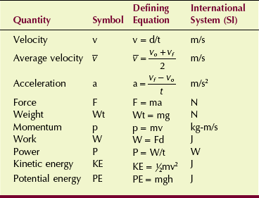
Similar to matter, energy can exist in several forms. In the International System (SI), energy is measured in joules (J). In radiology, the unit electron volt (eV) is often used.
Potential energy is the ability to do work by virtue of position. A guillotine blade held aloft by a rope and pulley is an example of an object that possesses potential energy (Figure 1-1). If the rope is cut, the blade will descend and do its ghastly task. Work is required to get the blade to its high position, and because of this position, the blade is said to possess potential energy. Other examples of objects that possess potential energy include a rollercoaster on top of the incline and the stretched spring of an open screen door.

FIGURE 1-1 The blade of a guillotine offers a dramatic example of both potential and kinetic energy. When the blade is pulled to its maximum height and is locked into place, it has potential energy. When the blade is allowed to fall, the potential energy is released as kinetic energy.
Kinetic energy is the energy of motion. It is possessed by all matter in motion: a moving automobile, a turning windmill wheel, a falling guillotine blade. These systems can all do work because of their motion.
Chemical energy is the energy released by a chemical reaction. An important example of this type of energy is that which is provided to our bodies through chemical reactions involving the foods we eat. At the molecular level, this area of science is called biochemistry. The energy released when dynamite explodes is a more dramatic example of chemical energy.
Electrical energy represents the work that can be done when an electron moves through an electric potential difference (voltage). The most familiar form of electrical energy is normal household electricity, which involves the movement of electrons through a copper wire by an electric potential difference of 110 volts (V). All electric apparatus, such as motors, heaters, and blowers, function through the use of electrical energy.
Thermal energy (heat) is the energy of motion at the molecular level. It is the kinetic energy of molecules and is closely related to temperature. The faster the molecules of a substance are vibrating, the more thermal energy the substance has and the higher is its temperature.
Nuclear energy is the energy that is contained within the nucleus of an atom. We control the release and use of this type of energy in electric nuclear power plants. An example of the uncontrolled release of nuclear energy is the atomic bomb.
Electromagnetic energy is perhaps the least familiar form of energy. It is the most important for our purposes, however, because it is the type of energy that is used in x-ray imaging. In addition to x-rays, electromagnetic energy includes radio waves; microwaves; and ultraviolet, infrared, and visible light.
Just as matter can be transformed from one size, shape, and form to another, so energy can be transformed from one type to another. In radiology, for example, electrical energy in the x-ray imaging system is used to produce electromagnetic energy (the x-ray), which then is converted to chemical energy in the radiographic film or an electrical signal in a digital image receptor.
Reconsider now the statement that all things can be classified as matter or energy. Look around you and think of absolutely anything, and you should be convinced of this statement. You should be able to classify anything as matter, energy, or both. Frequently, matter and energy exist side by side—a moving automobile has mass and kinetic energy; boiling water has mass and thermal energy; the Leaning Tower of Pisa has mass and potential energy.
Perhaps the strangest property associated with matter and energy is that they are interchangeable, a characteristic first described by Albert Einstein in his famous theory of relativity. Einstein’s mass-energy equivalence equation is a cornerstone of that theory.
This mass-energy equivalence serves as the basis for the atomic bomb, nuclear power plants, and certain nuclear medicine imaging modalities.
 Mass-Energy

where E is energy, m is mass, and c is the velocity (speed) of electromagnetic radiation (light) in a vacuum.
Energy emitted and transferred through space is called radiation. When a piano string vibrates, it is said to radiate sound; the sound is a form of radiation. Ripples or waves radiate from the point where a pebble is dropped into a still pond. Visible light, a form of electromagnetic energy, is radiated by the sun and is electromagnetic radiation. Electromagnetic energy is usually referred to as electromagnetic radiation or, simply, radiation.
Matter that intercepts radiation and absorbs part or all of it is said to be exposed or irradiated. Spending a day at the beach exposes you to ultraviolet light. Ultraviolet light is the type of radiation that causes sunburn. During a radiographic examination, the patient is exposed to x-rays. The patient is said to be irradiated.
Ionizing radiation is a special type of radiation that includes x-rays. Ionizing radiation is any type of radiation that is capable of removing an orbital electron from the atom with which it interacts (Figure 1-2). This type of interaction between radiation and matter is called ionization. Ionization occurs when an x-ray passes close to an orbital electron of an atom and transfers sufficient energy to the electron to remove it from the atom. The ionizing radiation may interact with and ionize additional atoms. The orbital electron and the atom from which it was separated are called an ion pair. The electron is a negative ion, and the remaining atom is a positive ion.
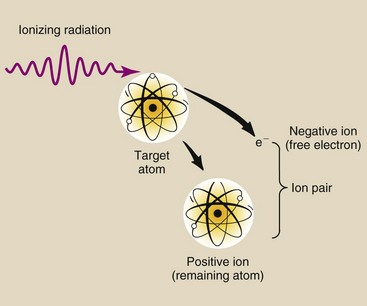
FIGURE 1-2 Ionization is the removal of an electron from an atom. The ejected electron and the resultant positively charged atom together are called an ion pair.
Thus, any type of energy that is capable of ionizing matter is known as ionizing radiation. X-rays, gamma rays, and ultraviolet light are the only forms of electromagnetic radiation with sufficient energy to ionize. Some fast-moving particles (particles with high kinetic energy) are also capable of ionization. Examples of particle-type ionizing radiation are alpha and beta particles (see Chapter 2). Although alpha and beta particles are sometimes called rays, this designation is incorrect.
Sources of Ionizing Radiation
Many types of radiation are harmless, but ionizing radiation can injure humans. We are exposed to many sources of ionizing radiation (Figure 1-3). These sources can be divided into two main categories: natural environmental radiation and man-made radiation.
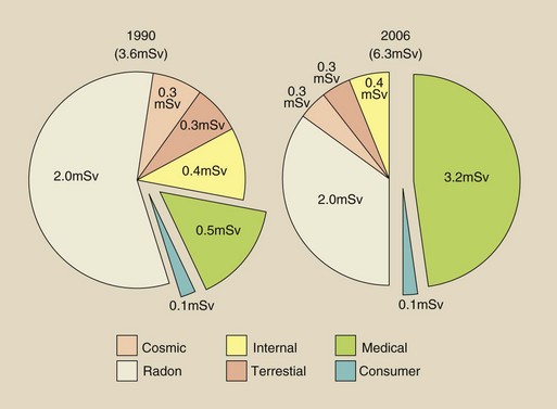
FIGURE 1-3 The contribution of various sources to the average U.S. population radiation dose, 1990. We will return to this very important pie chart in Chapter 37.
Natural environmental radiation results in an annual dose of approximately 3 millisieverts (mSv). Man-made radiation results in 3.2 mSv annually. An mSv is the unit of effective dose. It is used to express radiation exposure of populations and radiation risk in those populations.
Natural environmental radiation consists of four components: cosmic rays, terrestrial radiation, internally deposited radionuclides, and radon. Cosmic rays are particulate and electromagnetic radiation emitted by the sun and stars. On Earth, the intensity of cosmic radiation increases with altitude and latitude. Terrestrial radiation results from deposits of uranium, thorium, and other radionuclides in the Earth. The intensity is highly dependent on the geology of the local area. Internally deposited radionuclides, mainly potassium-40 (40K), are natural metabolites. They have always been with us and contribute an equal dose to each of us.
The largest source of natural environmental radiation is radon. Radon is a radioactive gas that is produced by the natural radioactive decay of uranium, which is present in trace quantities in the Earth. All Earth-based materials, such as concrete, bricks, and gypsum wallboard, contain radon. Radon emits alpha particles, which are not penetrating, and therefore contributes a radiation dose only to the lung.
Collectively, these sources of natural environmental radiation result in approximately 0.02 to 0.1 microgray (µGy)/hr at waist level in the United States (Figure 1-4). This equals an annual exposure of approximately 0.2 milligray (mGy)/yr along the Gulf Coast and Florida to 1 mGy/yr or higher in the Rocky Mountains region.

FIGURE 1-4 Radiation exposure at waist level throughout the United States. (Courtesy U.S. Geological Survey.)
Remember, however, that humans have existed for several hundred thousand years in the presence of this natural environmental radiation level. Human evolution undoubtedly has been influenced by natural environmental radiation. Some geneticists contend that evolution is influenced primarily by ionizing radiation. If this is so, then we must indeed be concerned with control of unnecessary radiation exposure because over the past century, with increasing medical applications of radiation, the average annual exposure of our population to radiation has increased significantly.
Diagnostic x-rays constitute the largest man-made source of ionizing radiation (3.2 mSv/yr). This estimate was made in 2006 by the National Council on Radiation Protection and Measurements (NCRP). Earlier estimates by the NCRP in 1990 put this source at nearly 0.4 mSv/yr. The increase during this 16-year period is principally attributable to the increasing use of computed tomography (CT) and high-level fluoroscopy.
The benefits derived from the application of x-rays in medicine are indisputable; however, such applications must be made with prudence and with care taken to reduce unnecessary exposure of patients and personnel. This responsibility falls primarily on radiologic technologists because they usually control the operation of x-ray imaging systems during radiologic examinations.
The currently accepted approximate annual dose resulting from medical applications of ionizing radiation is 3.2 mSv. In contrast to the natural environmental radiation dose, this level takes into account people who are not receiving a radiologic examination and those undergoing several within a year.
The medical radiation exposure for some in our population will be zero, but for others, it may be quite high. This average level is comparable with natural environmental radiation levels and one could question, therefore, why it is necessary to be concerned about radiation control and radiation safety in medical imaging.
Other sources of man-made radiation include nuclear power generation, research applications, industrial sources, and consumer items. Nuclear power stations and other industrial applications contribute very little to our radiation dose. Consumer products such as watch dials, exit signs, smoke detectors, camping lantern mantles, and airport surveillance systems contribute 0.1 mSv to our annual radiation dose.
Discovery of X-Rays
X-rays were not developed; they were discovered, and quite by accident. During the 1870s and 1880s, many university physics laboratories were investigating the conduction of cathode rays, or electrons, through a large, partially evacuated glass tube known as a Crookes tube. Sir William Crookes was an Englishman from a rather humble background who was a self-taught genius.
The tube that bears his name was the forerunner of modern fluorescent lamps and x-ray tubes. There were many different types of Crookes tubes; most of them were capable of producing x-rays. Wilhelm Roentgen was experimenting with a type of Crookes tube when he discovered x-rays (Figure 1-5).

FIGURE 1-5 The type of Crookes tube Roentgen used when he discovered x-rays. Cathode rays (electrons) leaving the cathode are attracted by high voltage to the anode, where they produce x-rays and fluorescent light. (Courtesy Gary Leach, Memorial Hermann Hospital.)
On November 8, 1895, Roentgen was working in his physics laboratory at Würzburg University in Germany. He had darkened his laboratory and completely enclosed his Crookes tube with black photographic paper so he could better visualize the effects of the cathode rays in the tube. A plate coated with barium platinocyanide, a fluorescent material, happened to be lying on a bench top several meters from the Crookes tube.
No visible light escaped from the Crookes tube because of the black paper that enclosed it, but Roentgen noted that the barium platinocyanide glowed. The intensity of the glow increased as the plate was brought closer to the tube; consequently, there was little doubt about the origin of the stimulus of the glow. This glow is called fluorescence.
Roentgen’s immediate approach to investigating this “X-light,” as he called it, was to interpose various materials—wood, aluminum, his hand!—between the Crookes tube and the fluorescing plate. The “X” was for unknown! He feverishly continued these investigations for several weeks.
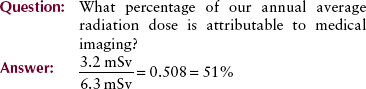
Roentgen’s initial investigations were extremely thorough, and he was able to report his experimental results to the scientific community before the end of 1895. For this work, in 1901, he received the first Nobel Prize in physics. Roentgen recognized the value of his discovery to medicine. He produced and published the first medical x-ray image in early 1896. It was an image of his wife’s hand (Figure 1-6). Figure 1-7 is a photograph of what is reported to be the first x-ray examination in the United States, conducted in early February 1896, in the physics laboratory at Dartmouth College.
FIGURE 1-6 The hand shown in this radiograph belongs to Mrs. Roentgen. This first indication of the possible medical applications of x-rays was made within a few days of the discovery. (Courtesy Deutsches Roentgen Museum.)
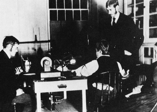
FIGURE 1-7 This photograph records the first medical x-ray examination in the United States. A young patient, Eddie McCarthy of Hanover, New Hampshire, broke his wrist while skating on the Connecticut River and submitted to having it photographed by the “X-light.” With him are (left to right) Professor E.B. Frost, Dartmouth College, and his brother, Dr. G.D. Frost, Medical Director, Mary Hitchcock Hospital. The apparatus was assembled by Professor F.G. Austin in his physics laboratory at Reed Hall, Dartmouth College, on February 3, 1896. (Courtesy Mary Hitchcock Hospital.)
The discovery of x-rays is characterized by many amazing features, and this causes it to rank high among the events in human history. First, the discovery was accidental. Second, probably no fewer than a dozen contemporaries of Roentgen had previously observed x-radiation, but none of these other physicists had recognized its significance or investigated it. Third, Roentgen followed his discovery with such scientific vigor that within little more than 1 month, he had described x-radiation with nearly all of the properties we recognize today.
Development of Modern Radiology
There are three general types of x-ray examinations: radiography, fluoroscopy, and CT. Radiography uses film or a solid-state image receptor and usually an x-ray tube mounted from the ceiling on a track that allows the tube to be moved in any direction. Such examinations provide the radiologist with fixed images.
Fluoroscopy is usually conducted with an x-ray tube located under the examination table. The radiologist is provided with moving images on a television monitor or flat panel display.
Computed tomography uses a rotating x-ray source and detector array. A volume of data is acquired so that fixed images can be reconstructed in any anatomical plane coronal, sagittal, transverse, or oblique.
There are many variations of these three basic types of examinations, but in general, x-ray equipment is similar.
 To provide an x-ray beam that is satisfactory for imaging, you must supply the x-ray tube with a high voltage and an electric current.
X-ray voltages are measured in kilovolt peak (kVp). One kilovolt (kV) is equal to 1000 V of electric potential. X-ray currents are measured in milliampere (mA), where the ampere (A) is a measure of electric current. The prefix milli stands for 1/1000 or 0.001.
| Question: | The usual x-ray source-to-image receptor distance (SID) during radiography is 1 m. How many millimeters is that? |
| Answer: | 1 mm = 1/1000 m or 10−3; therefore, 1000 mm = 1 m. |
Today, voltage and current are supplied to an x-ray tube through rather complicated electric circuits, but in Roentgen’s time, only simple static generators were available. These units could provide currents of only a few milliamperes and voltages to 50 kVp. Today, 1000 mA and 150 kVp are commonly used.
Early radiographic procedures often required exposure times of 30 minutes or longer. Long exposure time results in image blur. One development that helped reduce this exposure time was the use of a fluorescent intensifying screen in conjunction with the glass photographic plates.
Michael Pupin is said to have demonstrated the use of a radiographic intensifying screen in 1896, but only many years later did it receive adequate recognition and use. Radiographs during Roentgen’s time were made by exposing a glass plate with a layer of photographic emulsion coated on one side.
Charles L. Leonard found that by exposing two glass x-ray plates with the emulsion surfaces together, exposure time was halved, and the image was considerably enhanced. This demonstration of double-emulsion radiography was conducted in 1904, but double-emulsion film did not become commercially available until 1918.
Much of the high-quality glass used in radiography came from Belgium and other European countries. This supply was interrupted during World War I; therefore, radiologists began to make use of film rather than glass plates.
The demands of the army for increased radiologic services made necessary a substitute for the glass plate. The substitute was cellulose nitrate, and it quickly became apparent that the substitute was better than the original glass plate.
The fluoroscope was developed in 1898 by the American inventor Thomas A. Edison (Figure 1-8). Edison’s original fluorescent material was barium platinocyanide, a widely used laboratory material. He investigated the fluorescent properties of more than 1800 other materials, including zinc cadmium sulfide and calcium tungstate—two materials in use today.
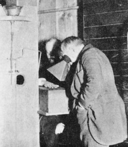
FIGURE 1-8 Thomas Edison is seen viewing the hand of his unfortunate assistant, Clarence Dally, through a fluoroscope of his own design. Dally’s hand rests on the box that contains the x-ray tube.
There is no telling what additional inventions Edison might have developed had he continued his x-ray research, but he abandoned it when his assistant and long-time friend, Clarence Dally, experienced a severe x-ray burn that eventually required amputation of both arms. Dally died in 1904 and is counted as the first x-ray fatality in the United States.
Two devices designed to reduce the exposure of patients to x-rays and thereby minimize the possibility of x-ray burn were introduced before the turn of the 20th century by a Boston dentist, William Rollins. Rollins used x-rays to image teeth and found that restricting the x-ray beam with a sheet of lead with a hole in the center, a diaphragm, and inserting a leather or aluminum filter improved the diagnostic quality of radiographs.
This first application of collimation and filtration was followed very slowly by general adoption of these techniques. It was later recognized that these devices reduce the hazard associated with x-rays.
Two developments that occurred at approximately the same time transformed the use of x-rays from a novelty in the hands of a few physicists into a valuable, large-scale medical specialty. In 1907, H.C. Snook introduced a substitute high-voltage power supply, an interrupterless transformer, for the static machines and induction coils then in use.
Although the Snook transformer was far superior to these other devices, its capability greatly exceeded the capability of the Crookes tube. It was not until the introduction of the Coolidge tube that the Snook transformer was widely adopted.
The type of Crookes tube that Roentgen used in 1895 had existed for a number of years. Although some modifications were made by x-ray workers, it remained essentially unchanged into the second decade of the 20th century.
After considerable clinical testing, William D. Coolidge unveiled his hot-cathode x-ray tube to the medical community in 1913. It was immediately recognized as far superior to the Crookes tube. It was a vacuum tube that allowed x-ray intensity and energy to be selected separately and with great accuracy. This had not been possible with gas-filled tubes, which made standards for techniques difficult to obtain. X-ray tubes in use today are refinements of the Coolidge tube.
Radiology emerged as a medical specialty because of the Snook transformer and the Coolidge x-ray tube.
The era of modern radiography is dated from the matching of the Coolidge tube with the Snook transformer; only then did acceptable kVp and mA levels become possible. Few developments since that time have had such a major influence on diagnostic imaging.
In 1913, Gustav Bucky (German) invented the stationary grid (“Glitterblende”); 2 months later, he applied for a second patent for a moving grid. In 1915, H. Potter (American), probably unaware of Bucky’s patent because of World War I, also invented a moving grid. To his credit, Potter recognized Bucky’s work, and the Potter-Bucky grid was introduced in 1921.
In 1946, the light amplifier tube was demonstrated at Bell Telephone Laboratories. This device was adapted for fluoroscopy by 1950 as an image intensifier tube. Today, image-intensified fluoroscopy is being replaced by solid-state image receptors.
Each recent decade has seen remarkable improvements in medical imaging. Diagnostic ultrasonography appeared in the 1960s, as did the gamma camera. Positron emission tomography (PET) and x-ray CT were developed in the 1970s. Magnetic resonance imaging (MRI) became an accepted modality in the 1980s, and now, digital radiography and digital fluoroscopy are rapidly replacing screen-film radiography and image-intensified fluoroscopy. Box 1-1 chronologically summarizes some of the more important developments.
Reports of Radiation Injury
The first x-ray fatality in the United States occurred in 1904. Unfortunately, radiation injuries occurred rather frequently in the early years. These injuries usually took the form of skin damage (sometimes severe), loss of hair, and anemia. Physicians and, more commonly, patients were injured, primarily because the low energy of radiation then available resulted in the necessity for long exposure times to obtain acceptable images.
By about 1910, these acute injuries began to be controlled as the biologic effects of x-rays were scientifically investigated and reported. With the introduction of the Coolidge tube and the Snook transformer, the frequency of reports of injuries to superficial tissues decreased.
Years later, it was discovered that blood disorders such as aplastic anemia and leukemia were occurring in radiologists at a much higher rate than in others. Because of these observations, protective devices and apparel, such as lead gloves and aprons, were developed for use by radiologists. X-ray workers were routinely observed for any effects of their occupational exposure and were provided with personnel radiation monitoring devices. This attention to radiation safety in radiology has been effective.
Basic Radiation Protection
Today, the emphasis on radiation control in diagnostic radiology has shifted back to protection of patients. Current studies suggest that even the low doses of x-radiation used in routine diagnostic procedures may result in a small incidence of latent harmful effects. It is also well established that human fetuses are sensitive to x-radiation early in pregnancy.
It is hoped that this introduction has emphasized the importance of providing adequate protection for both radiologic technologists and patients. As you progress through your training in radiologic technology, you will quickly learn how to operate your x-ray imaging systems safely, with minimal radiation exposures, by following standard radiation protection procedures.
One caution is in order early in your training—After you have worked with x-ray imaging systems, you will become so familiar with your work environment that you may become complacent about radiation control. Do not allow yourself to develop this attitude because it can lead to unnecessary radiation exposure. Radiation protection must be an important consideration during each x-ray procedure. Box 1-2 reports the Ten Commandments of Radiation Protection.
Minimizing radiation exposure to technologists and patients is easy if the x-radiation imaging systems designed for this purpose are recognized and understood. A brief description of some of the primary radiation protection devices follows.
Filtration
Metal filters, usually aluminum or copper, are inserted into the x-ray tube housing so that low-energy x-rays are absorbed before they reach the patient. These x-rays have little diagnostic value.
Collimation
Collimation restricts the useful x-ray beam to that part of the body to be imaged and thereby spares adjacent tissue from unnecessary radiation exposure. Collimators take many different forms. Adjustable light-locating collimators are the most frequently used collimating devices. Collimation also reduces scatter radiation and thus improves image contrast.
Intensifying Screens
Today, most x-ray films are exposed in a cassette, with radiographic intensifying screens on both sides of the film. Examinations conducted with radiographic intensifying screens reduce exposure of the patient to x-rays by more than 95% compared with examinations conducted without radiographic intensifying screens.
Protective Apparel
Lead-impregnated material is used to make aprons and gloves worn by radiologists and radiologic technologists during fluoroscopy and some radiographic procedures.
Gonadal Shielding
The same lead-impregnated material used in aprons and gloves is used to fabricate gonadal shields. Gonadal shields should be used with all persons of childbearing age when the gonads are in or near the useful x-ray beam and when use of such shielding will not interfere with the diagnostic value of the examination.
Protective Barriers
The radiographic or CT control console is always located behind a protective barrier. Often, the barrier is lead lined and is equipped with a leaded-glass window. Under normal circumstances, personnel remain behind the barrier during x-ray examination. Figure 1-9 is a rendering of a radiographic and fluoroscopic examination room. Many radiation safety features are illustrated.
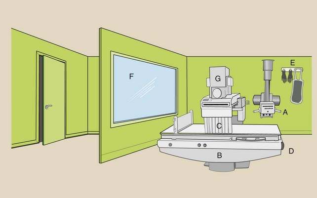
FIGURE 1-9 The general purpose radiographic and fluoroscopic imaging system includes an overhead radiographic tube (A) and a fluoroscopic examining table (B) with an x-ray tube under the table. Some of the more common radiation protection devices are the lead curtain (C), the Bucky slot cover (D), a leaded apron and gloves (E), and the protective viewing window (F). The location of the image intensifier (G) and of associated imaging equipment is shown.
Other procedures should be followed. Abdominal and pelvic x-ray examinations of expectant mothers should not be conducted during the first trimester unless absolutely necessary. Every effort should be made to ensure that an examination will not have to be repeated because of technical error. Repeat examinations subject the patient to twice the necessary radiation.
When shielding patients for x-ray examination, one should consider the medical management of the patient. Except for screening mammography, examination of asymptomatic patients is not indicated.
Patients who require assistance during examination should never be held by x-ray personnel. Mechanical immobilization devices should be used. When necessary, a member of the patient’s family, appropriately shielded, should provide the necessary assistance.
Standard Units of Measurement
Physics is the study of interactions of matter and energy in all their diverse forms. Similar to all scientists, physicists strive for exactness or certainty in describing these interactions. They try to remove the uncertainties by eliminating subjective descriptions of events. Assuming that all measurements are correctly made, all observers who use the methods of physics will obtain exactly the same results.
In addition to seeking certainty, physicists strive for simplicity; therefore, only three measurable quantities are considered basic. These base quantities are mass, length, and time, and they are the building blocks of all other quantities. Figure 1-10 indicates the role these base quantities play in supporting some of the other quantities used in radiologic science.

FIGURE 1-10 Base quantities support derived quantities, which in turn support the special quantities of radiologic science.
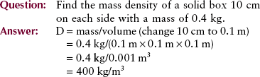
The secondary quantities are called derived quantities because they are derived from a combination of one or more of the three base quantities. For example, volume is length cubed (l3), mass density is mass divided by volume (m/l3), and velocity is length divided by time (l/t).
Additional quantities are designed to support measurement in specialized areas of science and technology. These additional quantities are called special quantities; in radiologic science, special quantities are those of exposure, dose, effective dose, and radioactivity.
Whether a physicist is studying something large, such as the universe, or something small, such as an atom, meaningful measurements must be reproducible. Therefore, after the fundamental quantities have been established, it is essential that they be related to a well-defined and invariable standard. Standards are normally defined by international organizations and usually are redefined when the progress of science requires greater precision.
Length
For many years, the standard unit of length was accepted to be the distance between two lines engraved on a platinum–iridium bar kept at the International Bureau of Weights and Measures in Paris, France. This distance was defined to be exactly 1 m. The English-speaking countries also base their standards of length on the meter.
In 1960, the need for a more accurate standard of length led to redefinition of the meter in terms of the wavelength of orange light emitted from an isotope of krypton (krypton-86). One meter is now defined as the distance traveled by light in 1/299,792,468 second.
Mass
The kilogram was originally defined to be the mass of 1000 cm3 of water at 4° Celsius (°C). In the same vault in Paris where the standard meter was kept, a platinum–iridium cylinder represents the standard unit of mass—the kilogram (kg), which has the same mass as 1000 cm3 of water. The kilogram is a unit of mass, and the newton and the pound, a British unit, are units of weight.
Time
The standard unit of time is the second (s). Originally, the second was defined in terms of the rotation of the Earth on its axis—the mean solar day. In 1956, it was redefined as a certain fraction of the tropical year 1900. In 1964, the need for a better standard of time led to another redefinition.
Now, time is measured by an atomic clock and is based on the vibration of cesium atoms. The atomic clock is capable of keeping time correctly to about 1 second in 5000 years.
Units
Every measurement has two parts: a magnitude and a unit. For example, the SID is 100 cm. The magnitude, 100, is not meaningful unless a unit is also designated. Here, the unit of measurement is the centimeter.
Table 1-1 shows four systems of units that represent base quantities. The International System (Le Système International d’Unités, SI), an extension of the MKS (meters, kilograms, and seconds) system, represents the current state of units. SI includes the three base units of the MKS system plus an additional four. Derived units and special units of the SI represent derived quantities and special quantities of radiologic science (Table 1-2).
TABLE 1-1

*The SI includes four additional base units.
†The pound is actually a unit of force that is related to mass.
TABLE 1-2
Special Quantities of Radiologic Science and Their Units
| Radiographic Quantities | Special Units | International System (SI) Units |
| Exposure | C/kg | Air kerma (Gya) |
| Dose | J/kg | Grayt (Gyt) |
| Effective dose | J/kg | Sievert (Sv) |
| Radioactivity | s−1 | Becquerel (Bq) |
The following would be unacceptable because of inconsistent units: mass density = 8.1 g/ft3 and pressure = 700 lb/cm2.
Mass density should be reported with units of kilograms per cubic meter (kg/m3). Pressure should be given in Newtons per square meter (N/m2).
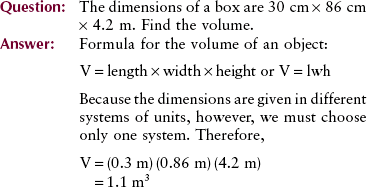
Note that the units are multiplied also: m × m × m = m3.
Mechanics
Mechanics is a segment of physics that deals with objects at rest (statics) and objects in motion (dynamics).
Velocity
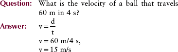
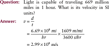
The motion of an object can be described with the use of two terms: velocity and acceleration. Velocity, sometimes called speed, is a measure of how fast something is moving or, more precisely, the rate of change of its position with time.
The velocity of a car is measured in kilometers per hour (miles per hour). Units of velocity in SI are meters per second (m/s). The equation for velocity (v) is as follows:

Often, the velocity of an object changes as its position changes. For example, a dragster running a race starts from rest and finishes with a velocity of 80 m/s. The initial velocity, designated by vo, is 0 (Figure 1-11). The final velocity, represented by vf, is 80 m/s. The average velocity can be calculated from the following expression:
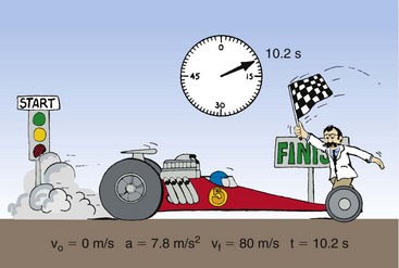
FIGURE 1-11 Drag racing provides a familiar example of the relationships among initial velocity, final velocity, acceleration, and time.

Acceleration
The rate of change of velocity with time is acceleration. It is how “quickly or slowly” the velocity is changing. Because acceleration is velocity divided by time, the unit is meters per second squared (m/s2).
If velocity is constant, acceleration is zero. On the other hand, a constant acceleration of 2 m/s2 means that the velocity of an object increased by 2 m/s each second. The defining equation for acceleration is given by the following:


Newton’s Laws of Motion
In 1686, the English scientist Isaac Newton presented three principles that even today are recognized as fundamental laws of motion.
Newton’s first law: Inertia—A body will remain at rest or will continue to move with constant velocity in a straight line unless acted on by an external force.
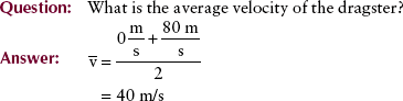
Newton’s first law states that if no force acts on an object, there will be no acceleration. The property of matter that acts to resist a change in its state of motion is called inertia. Newton’s first law is thus often referred to as the law of inertia (Figure 1-12). A mobile x-ray imaging system obviously will not move until forced by a push. Once in motion, however, it will continue to move forever, even when the pushing force is removed, unless an opposing force is present—friction.
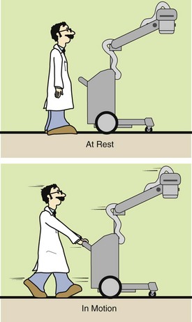
FIGURE 1-12 Newton’s first law states that a body at rest will remain at rest and a body in motion will continue in motion until acted on by an outside force.
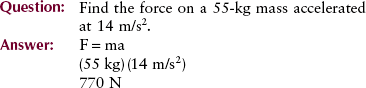
Newton’s second law: Force—The force (F) that acts on an object is equal to the mass (m) of the object multiplied by the acceleration (a) produced.
Newton’s second law is a definition of the concept of force. Force can be thought of as a push or pull on an object. If a body of mass m has an acceleration a, then the force on it is given by the mass times the acceleration. Newton’s second law is illustrated in Figure 1-13. Mathematically, this law can be expressed as follows:
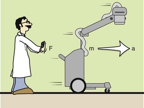
FIGURE 1-13 Newton’s second law states that the force applied to move an object is equal to the mass of the object multiplied by the acceleration.


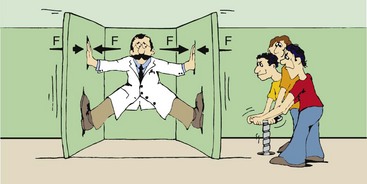
Newton’s third law of motion states that for every action, there is an equal and opposite reaction. “Action” was Newton’s word for “force.” According to this law, if you push on a heavy block, the block will push back on you with the same force that you apply. On the other hand, if you were the physics professor illustrated in Figure 1-14, whose crazed students had tricked him into the clamp room, no matter how hard you pushed, the walls would continue to close.
Weight
Weight (Wt) is a force on a body caused by the pull of gravity on it. Experiments have shown that objects that fall to Earth accelerate at a constant rate. This rate, termed the acceleration due to gravity and represented by the symbol g, is 9.8 m/s2 on Earth and 1.6 m/s2 on the moon.
Weightlessness observed in outer space is attributable to the absence of gravity. Thus, the value of gravity in outer space is zero. The weight of an object is equal to the product of its mass and the acceleration of gravity.

This example displays an important concept. The weight of an object can vary according to the value of gravity acting on it. Note, however, that the mass of an object does not change, regardless of its location. The student’s 75-kg mass remains the same on Earth, on the moon, or in space.
Momentum
The product of the mass of an object and its velocity is called momentum, represented by p. The greater the velocity of an object, the more momentum the object possesses. A truck accelerating down a hill, for example, gains momentum as its velocity increases.

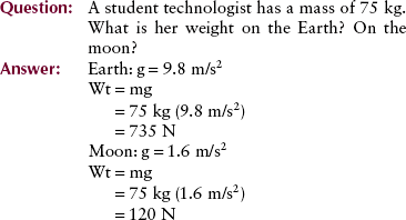
The total momentum before any interaction is equal to the total momentum after the interaction. Imagine a billiard ball colliding with two other balls at rest (Figure 1-15). The total momentum before the collision is the mass times the velocity of the cue ball. After the collision, this momentum is shared by the three balls. Thus, the original momentum of the cue ball is conserved after the interaction.
Work
Work, as used in physics, has specific meaning. The work done on an object is the force applied times the distance over which it is applied. In mathematical terms, the unit of work is the joule (J). When you lift a cassette, you are doing work. When the cassette is merely held motionless, however, no work (in the physics sense) is being performed even though considerable effort is being expended.

Power
Power is the rate of doing work. The same amount of work is required to lift a cassette to a given height, whether it takes 1 second or 1 minute to do so. Power gives us a way to include the time required to perform the work.

The SI unit of power is the joule/second (J/s), which is a watt (W). The British unit of power is the horsepower (hp).


Energy
There are many forms of energy, as previously discussed. The law of conservation of energy states that energy may be transformed from one form to another, but it cannot be created or destroyed; the total amount of energy is constant. For example, electrical energy is converted into light energy and heat energy in an electric light bulb. The unit of energy and work is the same, the joule.
Two forms of mechanical energy often are used in radiologic science: kinetic energy and potential energy. Kinetic energy is the energy associated with the motion of an object as expressed by the following:

It is apparent that kinetic energy depends on the mass of the object and on the square of its velocity.
where KE is kinetic energy. Potential energy is the stored energy of position or configuration. A textbook on a desk has potential energy because of its height above the floor … and the potential for a better job if it is read? It has the ability to do work by falling to the ground. Gravitational potential energy is given by the following:

A skier at the top of a jump, a coiled spring, and a stretched rubber band are examples of other systems that have potential energy because of their position or configuration.
If a scientist held a ball in the air atop the Leaning Tower of Pisa (Figure 1-16), the ball would have only potential energy, no kinetic energy. When it is released and begins to fall, the potential energy decreases as the height decreases. At the same time, the kinetic energy is increasing as the ball accelerates. Just before impact, the kinetic energy of the ball becomes maximum as its velocity reaches maximum. Because it now has no height, the potential energy becomes zero. All the initial potential energy of the ball has been converted into kinetic energy during the fall.
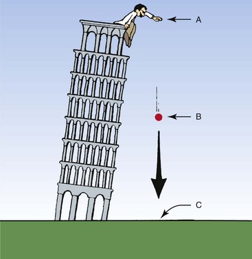
FIGURE 1-16 Potential energy results from the position of an object. Kinetic energy is the energy of motion. A, Maximum potential energy, no kinetic energy. B, Potential energy and kinetic energy. C, Maximum kinetic energy, no potential energy.
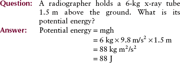
Table 1-3 presents a summary of the quantities and units in mechanics.
Heat
Heat is a form of energy that is very important to radiologic technologists. Excessive heat, a deadly enemy of an x-ray tube, can cause permanent damage. For this reason, the technologist should be aware of the properties of heat.
The more rapid and disordered the motion of molecules, the more heat an object contains. The unit of heat, the calorie, is defined as the heat necessary to raise the temperature of 1 g of water by 1°C. The same amount of heat will have different effects on different materials. For example, the heat required to change the temperature of 1 g of silver by 1°C is approximately 0.05 calorie, or only  that required for a similar temperature change in water.
Heat is transferred by conduction, convection, and radiation.
Conduction is the transfer of heat through a material or by touching. Molecular motion from a high-temperature object that touches a lower-temperature object equalizes the temperature of both.
Conduction is easily observed when a hot object and a cold object are placed in contact. After a short time, heat conducted to the cooler object results in equal temperatures of the two objects. Heat is conducted from an x-ray tube anode through the rotor to the insulating oil.
Convection is the mechanical transfer of “hot” molecules in a gas or liquid from one place to another. A steam radiator or forced-air furnace warms a room by convection. The air around the radiator is heated, causing it to rise, while cooler air circulates in and takes its place.
Thermal radiation is the transfer of heat by the emission of infrared radiation. The reddish glow emitted by hot objects is evidence of heat transfer by radiation. An x-ray tube cools primarily by radiation.
A forced-air furnace blows heated air into the room, providing forced circulation to complement the natural convection. Heat is convected from the housing of an x-ray tube to air.
Temperature normally is measured with a thermometer. A thermometer is usually calibrated at two reference points—the freezing and boiling points of water. The three scales that have been developed to measure temperature are Celsius (°C), Fahrenheit (°F), and Kelvin (K) (Figure 1-17).
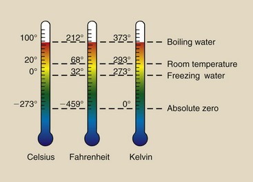
FIGURE 1-17 Three scales used to represent temperature. Celsius is the adopted scale for weather reporting everywhere except the United States. Kelvin is the scientific scale.
These scales are interrelated as follows:
Temperature Scales


The subscripts c, f, and k refer to Celsius, Fahrenheit, and Kelvin, respectively.
One can use the following for easy, approximate conversion:
Magnetic resonance imaging with a superconducting magnet requires extremely cold liquids called cryogens. Liquid nitrogen, which boils at 77 K, and liquid helium, which boils at 4 K, are the two cryogens that are used.
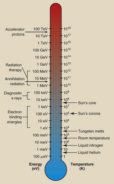
The relationship between temperature and energy is often represented by an energy thermometer (Figure 1-18). We consider x-rays to be energetic, although on the cosmic scale, they are rather ordinary.
Terminology for Radiologic Science
Every profession has its own language. Radiologic science is no exception. Several words and phrases characteristic of radiologic science already have been identified; many more will be defined and used throughout this book. For now, an introduction to this terminology should be sufficient.
Numeric Prefixes
Often in radiologic science, we must describe very large or very small multiples of standard units. Two units, the milliampere (mA) and kilovolt peak (kVp), already have been discussed. By writing 70 kVp instead of 70,000 volt peak, we can understandably express the same quantity with fewer characters. For such economy of expression, scientists have devised a system of prefixes and symbols (Table 1-4).
TABLE 1-4
Standard Scientific and Engineering Prefixes*
| Multiple | Prefix | Symbol |
| 1018 | exa- | E |
| 1015 | peta- | P |
| 1012 | tera- | T |
| 109 | giga- | G |
| 106 | mega- | M |
| 103 | kilo- | k |
| 102 | hecto- | h |
| 10 | deka- | da |
| 10−1 | deci- | d |
| 10−2 | centi- | c |
| 10−3 | milli- | m |
| 10−6 | micro- | µ |
| 10−9 | nano- | n |
| 10−12 | pico- | p |
| 10−15 | femto- | f |
| 10−18 | atto- | a |
*Boldfaced prefixes are those most frequently used in radiologic science.

Radiologic Units
The four units used to measure radiation should become a familiar part of your vocabulary. Figure 1-19 relates them to a hypothetical situation in which they would be used. Table 1-5 shows the relationship of the earlier radiologic units to their SI equivalents.
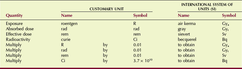
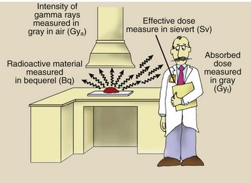
FIGURE 1-19 Radiation is emitted by radioactive material. The quantity of radioactive material is measured in becquerel. Radiation quantity is measured in gray or sievert, depending on the precise use.
In 1981, the International Commission on Radiation Units and Measurements (ICRU) issued standard units based on SI that have since been adopted by all countries except the United States. The NCRP and all U.S. scientific and medical societies adopted Le Système International d’Unités (The International System, SI) by the early 1990s.
Air Kerma (Kinetic Energy Released in Matter) (Gya)
Air kerma is the kinetic energy transferred from photons to electrons during ionization and excitation. Air kerma is measured in joule per kilogram (J/kg) where 1 J/kg is 1 gray (Gya).
In keeping with the adoption of the Wagner/Archer method described in the preface, the SI unit of air kerma (mGya) is used to express radiation exposure.
Absorbed Dose (Gyt)
Biologic effects usually are related to the radiation absorbed dose. Absorbed dose is the radiation energy absorbed per unit mass and has units of J/kg or Gyt. The units Gya and Gyt refer to radiation dose in air and tissue, respectively. For a given air kerma (radiation exposure), the absorbed dose depends on the type of tissue being irradiated. More about this is found in Chapters 9 and 39.
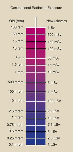
Sievert (Sv)
Occupational radiation monitoring devices are analyzed in terms of sievert, which is used to express the quantity of radiation received by radiation workers and populations.
Some types of radiation produce more damage than x-rays. The sievert accounts for these differences in biologic effectiveness. This is particularly important for persons working near nuclear reactors or particle accelerators.
Figure 1-20 summarizes the conversion from the old unit of occupational radiation exposure to SI units.
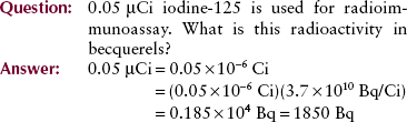
Becquerel (Bq)
The becquerel is the unit of quantity of radioactive material, not the radiation emitted by that material. One becquerel is that quantity of radioactivity in which a nucleus disintegrates every second (1 d/s = 1 Bq). Megabecquerels (MBq) are common quantities of radioactive material. Radioactivity and the becquerel have nothing to do with x-rays.
The Diagnostic Imaging Team
To become part of this exciting profession, a student must complete the prescribed academic courses, obtain clinical experience, and pass the national certification examination given by the American Registry of Radiologic Technologists (ARRT). Both academic expertise and clinical skills are required of radiographers (Box 1-3).
Summary
Radiology offers a career in many areas of medical imaging, and it requires a modest knowledge of medicine, biology, and physics (radiologic science). This first chapter weaves the history and development of radiography with an introduction to medical physics.
Medical physics includes the study of matter, energy, and the electromagnetic spectrum of which x-radiation is a part. The production of x-radiation and its safe, diagnostic use serve as the basis of radiology. As well as emphasizing the importance of radiation safety, this chapter presents a detailed list of clinical and patient care skills required of radiographers.
This chapter also introduces the various standards of measurement and applies them to concepts associated with mechanics and several areas that are associated with radiologic science. The technical aspects of radiologic science are complex requiring the identification and proper use of the units of radiation measurements.
1. Define or otherwise identify the following:
e. The average level of natural environmental radiation
2. Match the following dates with the appropriate event:
| a. 1901 | 1. Roentgen discovers x-rays. |
| b. 1907 | 2. Roentgen wins the first Nobel Prize in physics. |
| c. 1913 | 3. The Snook transformer is developed. |
| d. 1895 | 4. The Coolidge hot-cathode x-ray tube is introduced. |
3. Describe how weight is different from mass.
4. Name four examples of electromagnetic radiation.
5. How is x-ray interaction different from that seen in other types of electromagnetic radiation?
6. What is the purpose of x-ray beam filtration?
7. Describe the process that results in the formation of a negative ion and a positive ion.
8. What percentage of average radiation exposure to a human is attributable to medical x-rays?
9. What is the velocity of the mobile x-ray imaging system if the hospital elevator travels 20 m to the next floor in 30 s?
10. A radiographer has a mass of 58 kg. What is her weight on the earth? On the moon?
11. The acronym ALARA stands for what?
12. Name devices designed to minimize radiation exposure to the patient and the operator.
13. Liquid hydrogen with a boiling temperature of 77 K is used to cool some superconducting magnets. What is this temperature in degrees Celsius? In degrees Fahrenheit?
14. What are the three natural sources of whole-body radiation exposure?
15. What naturally occurring radiation source is responsible for radiation dose to lung tissue?
16. How would you define the term “radiation”?
17. What are the four special quantities of radiation measurement?
18. Place the following in chronologic order of appearance:
19. List five clinical skills required by the ARRT.
20. What are the three units common to the SI and MKS systems?
The answers to the Challenge Questions can be found by logging on to our website at http://evolve.elsevier. com.