The X-ray Tube
At the completion of this chapter, the student should be able to do the following:
1 Describe the general design of an x-ray tube.
2 List the external components that house and protect the x-ray tube.
3 Identify the purpose of the glass or metal enclosure.
4 Discuss the cathode and filament currents.
5 Describe the parts of the anode and the induction motor.
6 Define the line-focus principle and the heel effect.
THE X-RAY tube is a component of the x-ray imaging system rarely seen by radiologic technologists. It is contained in a protective housing and therefore is inaccessible. Figure 6-1 is a schematic diagram of a rotating anode diagnostic x-ray tube. Its components are considered separately, but it should be clear that there are two primary parts: the cathode and the anode. Each of these is an electrode, and any electronic tube with two electrodes is a diode. An x-ray tube is a special type of diode.
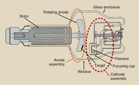
The external structure of the x-ray tube consists of three parts: the support structure, the protective housing, and the glass or metal enclosure. The internal structures of the x-ray tube are the anode and the cathode.
An explanation of the external components of the x-ray tube and the internal structure of the x-ray tube follows. The causes and prevention of x-ray tube failure are discussed.
With proper use, an x-ray tube used in general radiography should last many years. X-ray tubes used in computed tomography (CT) and interventional radiology generally have a much shorter life.
External Components
The x-ray tube and housing assembly are quite heavy; therefore, they require a support mechanism so the radiologic technologist can position them. Figure 6-2 illustrates the three main methods of x-ray tube support.
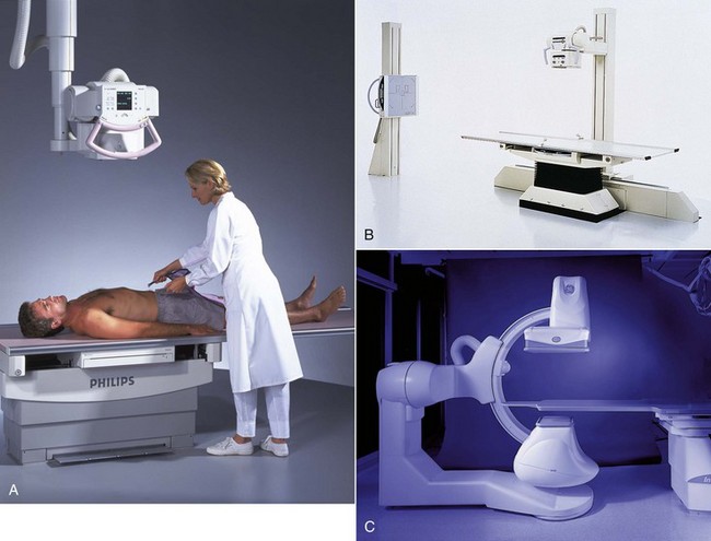
FIGURE 6-2 Three methods of supporting an x-ray tube. A, Ceiling support. B, Floor support. C, C-arm support. (A, Courtesy Philips Medical Systems. B, Courtesy Toshiba Corp. C, Courtesy GE Healthcare.)
Ceiling Support System
The ceiling support system is probably the most frequently used. It consists of two perpendicular sets of ceiling-mounted rails. This allows for both longitudinal and transverse travel of the x-ray tube.
A telescoping column attaches the x-ray tube housing to the rails, allowing for variable source-to-image receptor distance (SID). When the x-ray tube is centered above the examination table at the standard SID, the x-ray tube is in a preferred detent position.
Other positions can be chosen and locked by the radiologic technologist. Some ceiling-supported x-ray tubes have a single control that removes all locks, allowing the tube to “float.” This lock should be used only for minor adjustments and should not be used to move the tube farther than about 1 m because arm and shoulder strain can occur.
Floor-to-Ceiling Support System
The floor-to-ceiling support system has a single column with rollers at each end, one attached to a ceiling-mounted rail and the other attached to a floor-mounted rail. The x-ray tube slides up and down the column as the column rotates. A variation of this type of support system has the column positioned on a single floor support system with one or two floor-mounted rails.
C-Arm Support System
Interventional radiology suites often are equipped with C-arm support systems, so called because the system is shaped like a C. These systems are ceiling mounted and provide for very flexible x-ray tube positioning. The image receptor is attached to the other end of the C-arm from the x-ray tube. Variations called L-arm or U-arm support are also common.
Protective Housing
When x-rays are produced, they are emitted isotropically, that is, with equal intensity in all directions. We use only x-rays emitted through the special section of the x-ray tube called the window (Figure 6-3). The x-rays emitted through the window are called the useful beam.
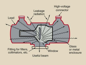
FIGURE 6-3 Protective housing reduces the intensity of leakage radiation to less than 1 mGya/hr at 1 m.
X-rays that escape through the protective housing are called leakage radiation; they contribute nothing in the way of diagnostic information and result in unnecessary exposure of the patient and the radiologic technologist. Properly designed protective housing reduces the level of leakage radiation to less than 1 mGya/hr at 1 m when operated at maximum conditions.
The protective housing incorporates specially designed high-voltage receptacles to protect against accidental electric shock. Death by electrocution was a very real hazard for early radiologic technologists. The protective housing also provides mechanical support for the x-ray tube and protects the tube from damage caused by rough handling.
The protective housing around some x-ray tubes contains oil that serves as both an insulator against electric shock and as a thermal cushion to dissipate heat. Some protective housings have a cooling fan to air cool the tube or the oil in which the x-ray tube is immersed. A bellows-like device allows the oil to expand when heated. If the expansion is too great, a microswitch is activated, so the tube cannot be used until it cools.
Glass or Metal Enclosure
An x-ray tube is an electronic vacuum tube with components contained within a glass or metal enclosure. The x-ray tube, however, is a special type of vacuum tube that contains two electrodes: the cathode and the anode. It is relatively large, perhaps 30 to 50 cm long and 20 cm in diameter. The glass enclosure is made of Pyrex glass to enable it to withstand the tremendous heat generated.
The enclosure maintains a vacuum inside the tube. This vacuum allows for more efficient x-ray production and a longer tube life. When just a little gas is in the enclosure, the electron flow from cathode to anode is reduced, fewer x-rays are produced, and more heat is generated.
Early x-ray tubes, modifications of the Crookes tube, were not vacuum tubes but rather contained controlled quantities of gas within the enclosure. The modern x-ray tube, the Coolidge tube, is a vacuum tube. If it becomes gassy, x-ray production falls, and the tube can fail.
An improvement in tube design incorporates metal rather than glass as part or all of the enclosure. As a glass enclosure tube ages, some tungsten vaporizes and coats the inside of the glass enclosure. This alters the electrical properties of the tube, allowing tube current to stray and interact with the glass enclosure; the result is arcing and tube failure.
Metal enclosure tubes maintain a constant electric potential between the electrons of the tube current and the enclosure. Therefore, they have a longer life and are less likely to fail. Virtually all high-capacity x-ray tubes now use metal enclosures.
The x-ray tube window is an area of the glass or metal enclosure, approximately 5 cm2, that is thin and through which the useful beam of x-rays is emitted. Such a window allows maximum emission of x-rays with minimum absorption.
Internal Components
Figure 6-4 shows a photograph of a dual-filament cathode and a schematic drawing of its electric supply. The two filaments supply separate electron beams to produce two focal spots.
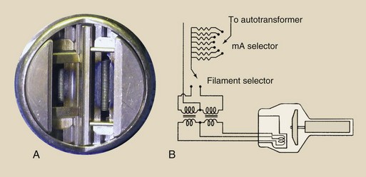
FIGURE 6-4 A, Dual-filament cathode designed to provide focal spots of 0.5 mm and 1.5 mm. B, Schematic for a dual-filament cathode.
 The cathode is the negative side of the x-ray tube; it has two primary parts, a filament and a focusing cup.
Filament
The filament is a coil of wire similar to that in a kitchen toaster, but it is much smaller. The filament is approximately 2 mm in diameter and 1 or 2 cm long. In the kitchen toaster, an electric current is conducted through the coil, causing it to glow and emit a large quantity of heat.
An x-ray tube filament emits electrons when it is heated. When the current through the filament is sufficiently high, the outer-shell electrons of the filament atoms are “boiled off” and ejected from the filament. This phenomenon is known as thermionic emission.
Filaments are usually made of thoriated tungsten. Tungsten provides for higher thermionic emission than other metals. Its melting point is 3410°C; therefore, it is not likely to burn out like the filament of a light bulb. Also, tungsten does not vaporize easily. If it did, the tube would become gassy quickly, and its internal parts would be coated with tungsten. The addition of 1% to 2% thorium to the tungsten filament enhances the efficiency of thermionic emission and prolongs tube life.
Tungsten vaporization with deposition on the inside of the glass enclosure is the most common cause of tube failure.
Ultimately, however, tungsten metal does vaporize and is deposited on internal components. This upsets some of the electric characteristics of the tube and can cause arcing and lead to tube failure. Such malfunction is usually abrupt.
Focusing Cup
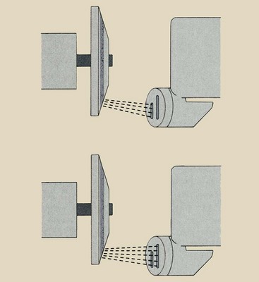
The filament is embedded in a metal shroud called the focusing cup (Figure 6-5). Because all of the electrons accelerated from cathode to anode are electrically negative, the electron beam tends to spread out owing to electrostatic repulsion. Some electrons can even miss the anode completely.
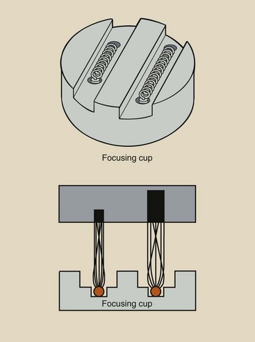
The focusing cup is negatively charged so that it electrostatically confines the electron beam to a small area of the anode (Figure 6-6). The effectiveness of the focusing cup is determined by its size and shape, its charge, the filament size and shape, and the position of the filament in the focusing cup.
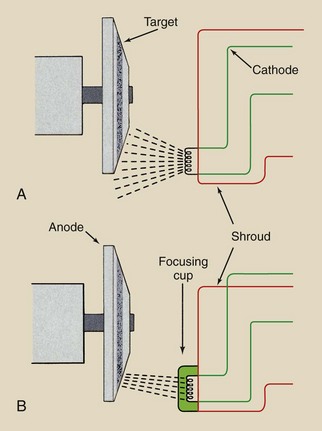
FIGURE 6-6 A, Without a focusing cup, the electron beam is spread beyond the anode because of mutual electrostatic repulsion among the electrons. B, With a focusing cup that is negatively charged, the electron beam is condensed and directed to the target.
Most rotating anode x-ray tubes have two filaments mounted in the cathode assemble “side by side,” creating large and small focal spot sizes. Filaments in biangle x-ray tubes have to be placed “end to end,” with the small focus filament above the large filament.
Certain types of x-ray tubes called grid-controlled tubes are designed to be turned on and off very rapidly. Grid-controlled tubes are used in portable capacitor discharge imaging systems and in digital subtraction angiography, digital radiography, and cineradiography, each of which requires multiple exposures for precise exposure time.
The term grid is borrowed from vacuum tube electronics and refers to an element in the tube that acts as the switch. In a grid-controlled x-ray tube, the focusing cup is the grid and therefore the exposure switch.
Filament Current
When the x-ray imaging system is first turned on, a low current passes through the filament to warm it and prepare it for the thermal jolt necessary for x-ray production. At low filament current, there is no tube current because the filament does not get hot enough for thermionic emission. When the filament current is high enough for thermionic emission, a small increase in filament current results in a large increase in x-ray tube current.
This relationship between filament current and x-ray tube current depends on the tube voltage (Figure 6-7). Fixed stations of 100, 200, 300 mA, and so forth usually correspond to discrete connections on the filament transformer or to precision resistors.
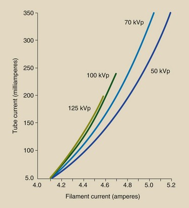
FIGURE 6-7 The x-ray tube current is actually controlled by changing the filament current. Because of thermionic emission, a small change in filament current results in a large change in tube current.
When emitted from the filament, electrons are in the vicinity of the filament before they are accelerated to the anode. Because these electrons carry negative charges, they repel one another and tend to form a cloud around the filament.
This cloud of electrons, called a space charge, makes it difficult for subsequent electrons to be emitted by the filament because of electrostatic repulsion. This phenomenon is called the space charge effect. A major obstacle in producing x-ray tubes with currents that exceed 1000 mA is the design of adequate space charge–compensating devices.
At any given filament current, say, 4.8 A (Figure 6-8), the x-ray tube current rises with increasing voltage to a maximum value. A further increase in kVp does not result in a higher mA because all of the available electrons have been used. This is the saturation current.
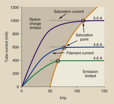
FIGURE 6-8 At a given filament current, tube current reaches a maximum level called saturation current.
Saturation current is not reached at a lower kVp because of space charge limitation. When an x-ray tube is operated at the saturation current, it is said to be emission limited.
Most diagnostic x-ray tubes have two focal spots—one large and the other small. The small focal spot is used when better spatial resolution is required. The large focal spot is used when large body parts are imaged and when other techniques that produce high heat are required.
Selection of one or the other focal spot is usually made with the mA station selector on the operating console. Normally, either filament can be used with the lower mA station—approximately 300 mA or less. At approximately 400 mA and up, only the larger focal spot is allowed because the heat capacity of the anode could be exceeded if the small focal spot were used.
Small focal spots range from 0.1 to 1 mm; large focal spots range from 0.3 to 2 mm. Each filament of a dual-filament cathode assembly is embedded in the focusing cup (Figure 6-9). The small focal spot size is associated with the small filament and the large focal spot size with the large filament. An electric current is directed through the appropriate filament.
Anode
The anode is the positive side of the x-ray tube. There are two types of anodes, stationary and rotating (Figure 6-10). Stationary anode x-ray tubes are used in dental x-ray imaging systems, some portable imaging systems, and other special-purpose units in which high tube current and power are not required. General-purpose x-ray tubes use the rotating anode because they must be capable of producing high-intensity x-ray beams in a short time.
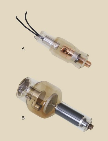
FIGURE 6-10 All diagnostic x-ray tubes can be classified according to the type of anode. A, Stationary anode. B, Rotating anode.
The anode is the positive side of the x-ray tube; it conducts electricity and radiates heat and contains the target.
The anode serves three functions in an x-ray tube. The anode is an electrical conductor. It receives electrons emitted by the cathode and conducts them through the tube to the connecting cables and back to the high-voltage generator. The anode also provides mechanical support for the target.
The anode also must be a good thermal dissipater. When the projectile electrons from the cathode interact with the anode, more than 99% of their kinetic energy is converted into heat. This heat must be dissipated quickly. Copper, molybdenum, and graphite are the most common anode materials. Adequate heat dissipation is the major engineering hurdle in designing higher capacity x-ray tubes.
Target
The target is the area of the anode struck by the electrons from the cathode. In stationary anode tubes, the target consists of a tungsten alloy embedded in the copper anode (Figure 6-11, A). In rotating anode tubes, the entire rotating disc is the target (Figure 6-11, B).
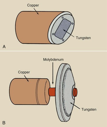
FIGURE 6-11 A, In a stationary anode tube, the target is embedded in the anode. B, In a rotating anode tube, the target is the rotating disc.
Alloying the tungsten (usually with rhenium) gives it added mechanical strength to withstand the stresses of high-speed rotation and the effects of repetitive thermal expansion and contraction. High-capacity x-ray tubes have molybdenum or graphite layered under the tungsten target (Figure 6-12). Both molybdenum and graphite have lower mass density than tungsten, making the anode lighter and easier to rotate.
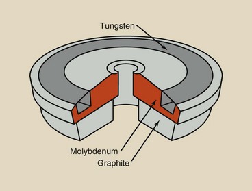
FIGURE 6-12 A layered anode consists of a target surface backed by one or more layers to increase heat capacity.
 Tungsten is the material of choice for the target for general radiography for three main reasons:
1. Atomic number—Tungsten’s high atomic number, 74, results in high-efficiency x-ray production and in high-energy x-rays. The reason for this is discussed more fully in Chapter 9.
2. Thermal conductivity—Tungsten has a thermal conductivity nearly equal to that of copper. It is therefore an efficient metal for dissipating the heat produced.
3. High melting point—Any material, if heated sufficiently, will melt and become liquid. Tungsten has a high melting point (3400°C compared with 1100°C for copper) and therefore can stand up under high tube current without pitting or bubbling.
Specialty x-ray tubes for mammography have molybdenum or rhodium targets principally because of their low atomic number and low K-characteristic x-ray energy. This concept is discussed fully in Chapter 7. Table 6-1 summarizes the properties of these target materials.
TABLE 6-1
Characteristics of X-ray Targets
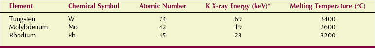
*X-rays resulting from electron transitions into the K shell.
Rotating Anode
The rotating anode x-ray tube allows the electron beam to interact with a much larger target area; therefore, the heating of the anode is not confined to one small spot, as in a stationary anode tube. Figure 6-13 compares the target areas of typical stationary anode (4 mm2) and rotating anode (1800 mm2) x-ray tubes with 1-mm focal spots. Thus, the rotating anode tube provides nearly 500 times more area to interact with the electron beam than is provided by a stationary anode tube.
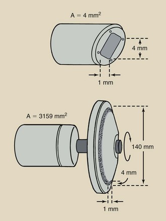
FIGURE 6-13 Stationary anode tube with a 1-mm focal spot may have a target area of 4 mm2. A comparable 15-cm–diameter rotating anode tube can have a target area of approximately 1800 mm2, which increases the heating capacity of the tube by a factor of nearly 500.
Heat capacity can be further improved by increasing the speed of anode rotation. Most rotating anodes revolve at 3400 rpm (revolutions per minute). The anodes of high-capacity x-ray tubes rotate at 10,000 rpm.
The stem of the anode is the shaft between the anode and the rotor. It is narrow so as to reduce its thermal conductivity. The stem usually is made of molybdenum because it is a poor heat conductor.
Occasionally, the rotor mechanism of a rotating anode tube fails. When this happens, the anode becomes overheated and pits or cracks, causing tube failure (Figure 6-14).
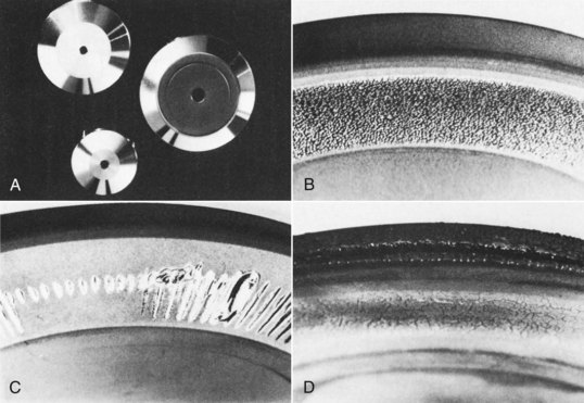
FIGURE 6-14 Comparison of smooth, shiny appearances of rotating anodes when new (A) versus their appearance after failure (B–D). Examples of anode separation and surface melting shown were caused by slow rotation caused by bearing damage (B), repeated overload (C), and exceeding of maximum heat storage capacity (D). (Courtesy Philips Medical Systems.)
Induction Motor
How does the anode rotate inside an enclosure with no mechanical connection to the outside? Most things that revolve are powered by chains or axles or gears of some sort.
An electromagnetic induction motor is used to turn the anode. An induction motor consists of two principal parts separated from each other by the glass or metal enclosure (Figure 6-15). The part outside the glass or metal enclosure, called the stator, consists of a series of electromagnets equally spaced around the neck of the tube. Inside the enclosure is a shaft made of bars of copper and soft iron fabricated into one mass. This part is called the rotor.
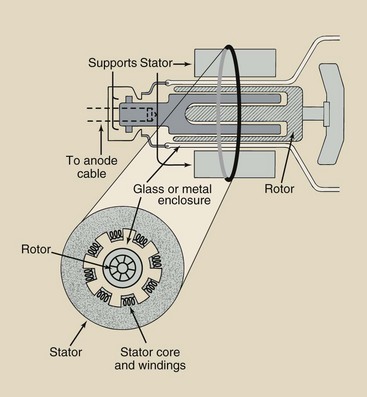
FIGURE 6-15 The target of a rotating anode tube is powered by an induction motor, the principal components of which are the stator and the rotor.
The induction motor works through electromagnetic induction, similar to a transformer. Current in each stator winding induces a magnetic field that surrounds the rotor. The stator windings are energized sequentially so that the induced magnetic field rotates on the axis of the stator. This magnetic field interacts with the ferromagnetic rotor, causing it to rotate synchronously with the activated stator windings.
When the radiologic technologist pushes the exposure button of a radiographic imaging system, there is a short delay before an exposure is made. This allows the rotor to accelerate to its designated rpm while the filament is heated. Only then is the kVp applied to the x-ray tube.
During this time, filament current is increased to provide the correct x-ray tube current. When a two-position exposure switch is used, the switch should be pushed to its final position in one motion. This minimizes the time that the filament is heated and prolongs tube life.
When the exposure is completed on imaging systems equipped with high-speed rotors, one can hear the rotor slow down and stop within approximately 1 min. The high-speed rotor slows down as quickly as it does because the induction motor is put into reverse. The rotor is a precisely balanced, low-friction device that, if left alone, might take many minutes to coast to rest after use.
In a new x-ray tube, the coast time is approximately 60 s. With age, the coast time is reduced because of wear of the rotor bearings.
One design that allows for massive anodes uses a shaft fixed at each end (Figure 6-16). In this x-ray tube, the anode is attached to the enclosure, and the whole insert rotates. The cathode is positioned on the axis, and the electron beam is deflected electromagnetically onto the anode.
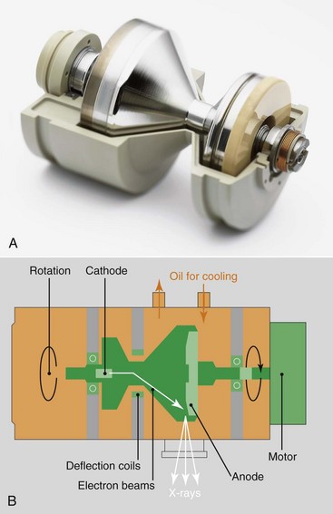
FIGURE 6-16 A, This very high capacity x-ray tube revolves in a bath of oil for complete heat dissipation. B, The cooling capacity is greater than any heat load. (Courtesy Siemens Medical Systems.)
Because the disc is part of the enclosure, the cooling oil is in contact with the back of the anode, allowing optimum cooling. The principal advantages are improved heat dissipation and greater capacity.
Line-Focus Principle
The focal spot is the area of the target from which x-rays are emitted. Radiology requires small focal spots because the smaller the focal spot, the better the spatial resolution of the image. Unfortunately, as the size of the focal spot decreases, the heating of the target is concentrated onto a smaller area. This is the limiting factor to focal spot size.
Before the rotating anode was developed, another design was incorporated into x-ray tube targets to allow a large area for heating while maintaining a small focal spot. This design is known as the line-focus principle. By angling the target (Figure 6-17), one makes the effective area of the target much smaller than the actual area of electron interaction.
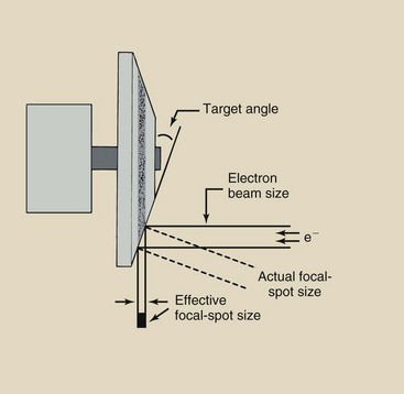
FIGURE 6-17 The line-focus principle allows high anode heating with small effective focal spots. As the target angle decreases, so does the effective focal spot size.
The effective target area, or effective focal spot size, is the area projected onto the patient and the image receptor. This is the value given when large or small focal spots are identified. When the target angle is made smaller, the effective focal spot size also is made smaller. Diagnostic x-ray tubes have target angles that vary from approximately 5 to 20 degrees.
The limiting factor in target angle is the ability of the cone of x-rays produced to adequately cover the largest field size used. In general radiography, this is usually taken as the diagonal of a 35- × 43-cm image receptor, which is approximately 55 cm.
When a smaller image receptor is used, the anode angle can be steeper. The advantage of the line-focus principle is that it simultaneously improves spatial resolution and heat capacity.
The line-focus principle results in an effective focal spot size much less than the actual focal spot size.
Biangular targets are available that produce two focal spot sizes because of two different target angles on the anode (Figure 6-18). Combining biangular targets with different-length filaments results in a very flexible combination.
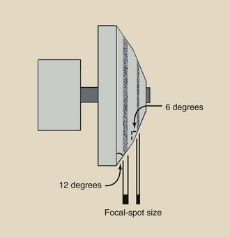
FIGURE 6-18 Some targets have two angles to produce two focal spots. To achieve this, the filaments must be placed one above the other.
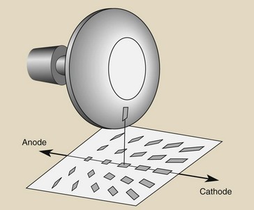
A circular effective focal spot is preferred. Usually, however, it has a shape characterized as a double banana (Figure 6-19). These differences in x-ray intensity across the focal spot are controlled principally by the design of the filament and focusing cup and by the voltage on the focusing cup. Round focal spots are particularly important for high-resolution magnification radiography and mammography.
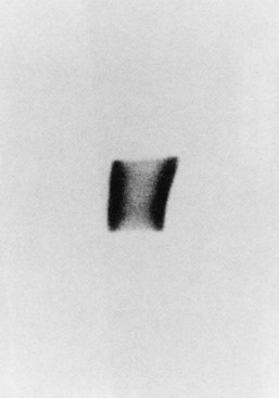
FIGURE 6-19 The usual shape of a focal spot is the double banana. (Courtesy Donald Jacobson, Medical College of Wisconsin.)
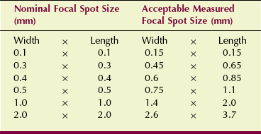
The National Electrical Manufacturers Association has established standards and variances for focal spot sizes. When a manufacturer states a focal spot size, that is its nominal size. Table 6-2 shows the maximum measured size permitted that is still within the standard.
Heel Effect
One unfortunate consequence of the line-focus principle is that the radiation intensity on the cathode side of the x-ray field is greater than that on the anode side. Electrons interact with target atoms at various depths into the target.
The x-rays that constitute the useful beam emitted toward the anode side must traverse a greater thickness of target material than the x-rays emitted toward the cathode direction (Figure 6-20). The intensity of x-rays that are emitted through the “heel” of the target is reduced because they have a longer path through the target and therefore increased absorption. This is the heel effect.
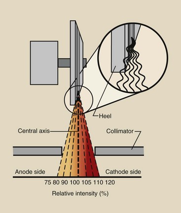
FIGURE 6-20 The heel effect results in reduced x-ray intensity on the anode side of the useful beam caused by absorption in the “heel” of the target.
The difference in radiation intensity across the useful beam of an x-ray field can vary by as much as 45%. The central ray of the useful beam is the imaginary line generated by the centermost x-ray in the beam. If the radiation intensity along the central ray is designated as 100%, then the intensity on the cathode side may be as high as 120%, and that on the anode side may be as low as 75%.
The heel effect is important when one is imaging anatomical structures that differ greatly in thickness or mass density. In general, positioning the cathode side of the x-ray tube over the thicker part of the anatomy provides more uniform radiation exposure of the image receptor. The cathode and anode directions are usually indicated on the protective housing, sometimes near the cable connectors.
In chest radiography, for example, the cathode should be inferior. The lower thorax in the region of the diaphragm is considerably thicker than the upper thorax and therefore requires higher radiation intensity if x-ray exposure of the image receptor is to be uniform.
In abdominal imaging, on the other hand, the cathode should be superior. The upper abdomen is thicker than the lower abdomen and pelvis and requires greater x-ray intensity for uniform x-ray exposure.
Figure 6-21 shows two posteroanterior chest images—one taken with the cathode down and the other with the cathode up. Can you tell the difference? Which do you think represents better radiographic quality? Resolve the difference before looking at the figure legend.
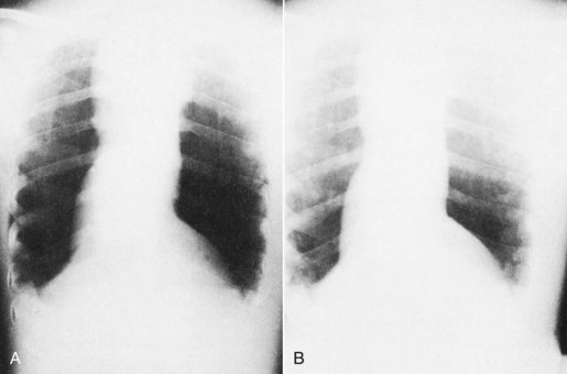
FIGURE 6-21 Posteroanterior chest images demonstrate the heel effect. A, Images taken with the cathode up (superior). B, Image with cathode down (inferior). More uniform radiographic density is obtained with the cathode positioned to the thicker side of the anatomy, as in B. (Courtesy Pat Duffy, Roxbury Community College.)
In mammography, the x-ray tube is designed so that the more intense side of the x-ray beam, the cathode side, is positioned toward the chest wall. With angling of the x-ray tube, advantage can be taken of the foreshortening that occurs to the focal spot size, resulting in an even smaller effective focal spot size.
Another important consequence of the heel effect is changing focal spot size. The effective focal spot is smaller on the anode side of the x-ray field than on the cathode side (Figure 6-22). Some manufacturers of mammography equipment take advantage of this property by angling the x-ray tube to produce the smaller focal spot along the chest wall.
Off-Focus Radiation
X-ray tubes are designed so that projectile electrons from the cathode interact with the target only at the focal spot. However, some of the electrons bounce off the focal spot and then land on other areas of the target, causing x-rays to be produced from outside of the focal spot (Figure 6-23).
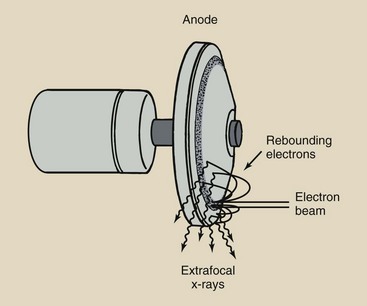
FIGURE 6-23 Extrafocal x-rays result from interaction of electrons with the anode off of the focal spot.
These x-rays are called off-focus radiation. This is similar to squirting a water pistol at a concrete pavement: Some of the water splashes off the pavement and lands in a larger area.
Off-focus radiation is undesirable because it extends the size of the focal spot. The additional x-ray beam area increases skin dose modestly but unnecessarily. Off-focus radiation can significantly reduce image contrast.
Finally, off-focus radiation can image patient tissue that was intended to be excluded by the variable-aperture collimators. Examples of such undesirable images are the ears in a skull examination, the soft tissue beyond the cervical spine, and the lungs beyond the borders of the thoracic spine.
Off-focus radiation is reduced by designing a fixed diaphragm in the tube housing near the window of the x-ray tube (Figure 6-24). This is a geometric solution.
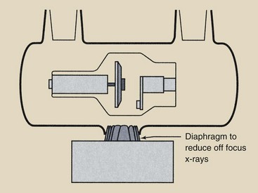
FIGURE 6-24 An additional diaphragm is positioned close to the focal spot to reduce extrafocal radiation.
Another effective solution is the metal enclosure x-ray tube. Electrons reflected from the focal spot are extracted by the metal enclosure and conducted away. Therefore, they are not available to be attracted to the target outside of the focal spot. The use of a grid does not reduce off-focus radiation.
X-Ray Tube Failure
With careful use, x-ray tubes can provide many years of service. With inconsiderate use, x-ray tube life may be shortened substantially.
The length of x-ray tube life is primarily under the control of radiologic technologists. Basically, x-ray tube life is extended by using the minimum radiographic factors of mA, kVp, and exposure time that are appropriate for each examination. The use of faster image receptors results in longer tube life.
X-ray tube failure has several causes, most of which are related to the thermal characteristics of the x-ray tube. Enormous heat is generated in the anode of the x-ray tube during x-ray exposure. This heat must be dissipated for the x-ray tube to continue to function.
This heat can be dissipated in one of three ways: radiation, conduction, or convection (Figure 6-25). Radiation is the transfer of heat by the emission of infrared radiation. Heat lamps emit not only visible light but also infrared radiation.
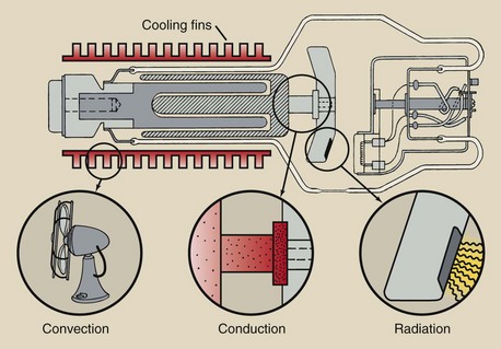
FIGURE 6-25 Heat from an anode is dissipated by radiation, conduction, or convection, most often radiation.
Conduction is the transfer of energy from one area of an object to another. The handle of a heated iron skillet becomes hot because of conduction. Convection is the transfer of heat by the movement of a heated substance from one place to another. Many homes and offices are heated by the convection of hot air.
All three modes of heat transfer occur in an x-ray tube. Most of the heat is dissipated by radiation during exposure. The anode may glow red hot. It always emits infrared radiation.
Unfortunately, some heat is conducted through the neck of the anode to the rotor and glass enclosure. The heated glass enclosure raises the temperature of the oil bath; this convects the heat to the tube housing and then to room air.
When the temperature of the anode is excessive during a single exposure, localized surface melting and pitting of the anode can occur. These surface irregularities result in variable and reduced radiation output. If surface melting is sufficiently severe, the tungsten can be vaporized and can plate the inside of the glass enclosure. This can cause filtering of the x-ray beam and interference with electron flow from the cathode to the anode.
If the temperature of the anode increases too rapidly, the anode may crack, becoming unstable in rotation and rendering the tube useless. If maximum techniques are required for a particular examination, the anode should first be warmed by low-technique operation.
A second type of x-ray tube failure results from maintaining the anode at elevated temperatures for prolonged periods. During exposures lasting 1 to 3 s, the temperature of the anode may be sufficient to cause it to glow like an incandescent light bulb. During exposure, heat is dissipated by radiation.
Between exposures, heat is dissipated, primarily through conduction, to the oil bath in which the tube is immersed. Some heat is conducted through the narrow molybdenum neck to the rotor assembly; this can cause subsequent heating of the rotor bearings. Excessive heating of the bearings results in increased rotational friction and an imbalance of the rotor anode assembly. Bearing damage is another cause of tube failure.
If thermal stress on the x-ray tube anode is maintained for prolonged periods, such as during fluoroscopy, the thermal capacity of the total anode system and of the x-ray tube housing is the limitation to operation. During fluoroscopy, the x-ray tube current is usually less than 5 mA, rather than hundreds of mA as in radiography.
Under such fluoroscopic conditions, the rate of heat dissipation from the rotating target attains equilibrium with the rate of heat input, and this rate rarely is sufficient to cause surface defects in the target. However, the x-ray tube can fail because of the continuous heat delivered to the rotor assembly, the oil bath, and the x-ray tube housing. Bearings can fail, the glass enclosure can crack, and the tube housing can fail.
A final cause of tube failure involves the filament. Because of the high temperature of the filament, tungsten atoms are vaporized slowly and plate the inside of the glass or metal enclosure even with normal use. This tungsten, along with that vaporized from the anode, can disturb the electric balance of the x-ray tube, causing abrupt, intermittent changes in tube current, which often lead to arcing and tube failure.
The most frequent cause of abrupt tube failure is electron arcing from the filament to the enclosure because of vaporized tungsten.
With excessive heating of the filament caused by high mA operation for prolonged periods, more tungsten is vaporized. The filament wire becomes thinner and eventually breaks, producing an open filament. This same type of failure occurs when an incandescent light bulb burns out.
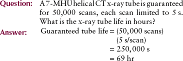
In the same way that the life of a light bulb is measured in hours—2000 hours is standard—that of an x-ray tube is measured in tens of thousands of exposures. Most CT tubes are now guaranteed for 50,000 exposures.
Rating Charts
Radiologic technologists are guided in the use of x-ray tubes by x-ray tube rating charts. It is essential that technologists be able to read and understand these charts even though many of these charts are now digitally stored in the operating console. Three types of x-ray tube rating charts are particularly important: the radiographic rating chart, the anode cooling chart, and the housing cooling chart.
Radiographic Rating Chart
Of the three rating charts, the radiographic rating chart is the most important because it conveys which radiographic techniques are safe and which techniques are unsafe for x-ray tube operation. Each chart shown in Figure 6-26 contains a family of curves representing the various tube currents in mA. The x-axis and the y-axis show scales of the two other radiographic parameters, time and kVp.
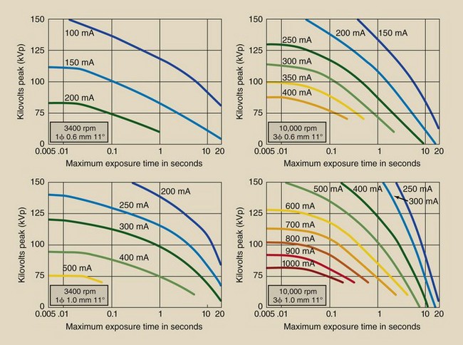
FIGURE 6-26 Representative radiographic rating charts for a given x-ray tube. Each chart specifies the conditions of operation under which it applies. (Courtesy GE Healthcare.)
For a given mA, any combination of kVp and time that lies below the mA curve is safe. Any combination of kVp and time that lies above the curve representing the desired mA is unsafe. If an unsafe exposure was made, the tube might fail abruptly. Most x-ray imaging systems have a microprocessor control that does not allow an unsafe exposure.
A series of radiographic rating charts accompanies every x-ray tube. There are different charts for the filament in use (large or small focal spot), the speed of anode rotation (3400 or 10,000 rpm), the target angle, and the voltage rectification (half wave, full wave, three phase, high frequency).
Be sure to use the proper radiographic rating chart with each tube. This is particularly important after x-ray tubes have been replaced. An appropriate radiographic rating chart is supplied with each replacement x-ray tube and can be different from that of the original tube.
The application of radiographic rating charts is not difficult and can be used as a tool to check the proper functioning of the microprocessor protection circuit.
1. The first intersection is approximately 350 mA at 0.03 s = 10.5 mAs. Not enough.
2. The next intersection is approximately 300 mA at 0.2 s = 60 mAs. Not enough.
3. The next intersection is approximately 250 mA at 0.6 s = 150 mAs. This is sufficient. Consequently, 0.6 s is the minimum possible exposure time.
Anode Cooling Chart
The anode has a limited capacity for storing heat. Although heat is dissipated to the oil bath and x-ray tube housing, it is possible through prolonged use or multiple exposures to exceed the heat storage capacity of the anode.
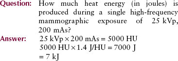
In x-ray applications, thermal energy is measured in heat units (HUs) or Joules (J). One heat unit is equal to the product of 1 kVp, 1 mA, and 1 s. One heat unit is also equal to 1.4 J. Calories and British thermal units (BTUs) are other familiar thermal energy units.
More heat is generated when three-phase equipment and high-frequency equipment are used than when single-phase equipment is used. A modification factor of 1.4 is necessary for calculating three-phase or high-frequency heat units.
The thermal capacity of an anode, and its heat dissipation characteristics are contained in a rating chart called an anode cooling chart (Figure 6-27). Different from the radiographic rating chart, the anode cooling chart does not depend on the filament size or the speed of rotation.
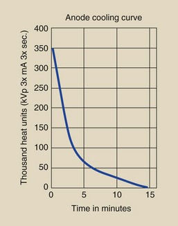
FIGURE 6-27 Anode cooling chart shows time required for heated anode to cool. (Courtesy GE Healthcare.)
The tube represented in Figure 6-27 has a maximum anode heat capacity of 350,000 HU. The chart shows that if the maximum heat load were attained, it would take 15 minutes for the anode to cool completely.
The rate of cooling is rapid at first and slows as the anode cools. In addition to determining the maximum heat capacity of the anode, the anode cooling chart is used to determine the length of time required for complete cooling after any level of heat input.
| Question: | A particular examination results in delivery of 50,000 HU to the anode in a matter of seconds. How long will it take the anode to cool completely? |
| Answer: | The 50,000-HU level intersects the anode cooling curve at approximately 6 minutes. From that point on, the curve to complete cooling requires an additional 9 minutes (15 − 6 = 9). Therefore, 9 minutes is required for complete cooling. |
Although the heat generated in producing x-rays is expressed in heat units, joules are the equivalent. By definition:
Housing Cooling Chart
The cooling chart for the housing of the x-ray tube has a shape similar to that of the anode cooling chart and is used in precisely the same way. Radiographic x-ray tube housings usually have maximum heat capacities in the range of several million heat units. Complete cooling after maximum heat capacity requires from 1 to 2 hours.
Summary
The primary support structure for the x-ray tube, which allows the greatest ease of movement and range of position, is the ceiling support system. Protective housing covers the x-ray tube and provides the following three functions: it (1) reduces leakage radiation to less than 1 mGya/hr at 1 m; (2) provides mechanical support, thereby protecting the tube from damage; and (3) serves as a way to conduct heat away from the x-ray tube target.
The glass or metal enclosure surrounds the cathode (−) and the anode (+), which are the electrodes of the vacuum tube. The cathode contains the tungsten filament, which is the source of electrons. The rotating anode is the tungsten–rhenium disc, which serves as a target for electrons accelerated from the cathode. The line-focus principle results from angled targets. The heel effect is the variation in x-ray intensity across the x-ray beam that results from absorption of x-rays in the heel of the target.
Safe operation of the x-ray tube is the responsibility of radiographers. Tube failure can be prevented. The causes of tube failure are threefold:
• A single excessive exposure causes pitting or cracking of the anode.
• Long exposure time causes excessive heating of the anode, resulting in damage to the bearings in the rotor assembly. Bearing damage causes warping and rotational friction of the anode.
• Even with normal use, vaporization of the filament causes tungsten to coat the glass or metal enclosure; this eventually causes arcing.
Tube rating charts printed by manufacturers of x-ray tubes aid the radiographer in using acceptable exposure levels to maximize x-ray tube life.
1. Define or otherwise identify the following:
2. List the three methods used to support x-ray tubes and briefly describe each.
3. Where in an x-ray imaging system is thoriated tungsten used?
4. What is saturation current?
5. Why are arcing and tube failure no longer major problems in modern x-ray tube design?
6. Explain the phenomenon of thermionic emission.
7. What addition to the filament material prolongs tube life?
8. What is the reason for the filament to be embedded in the focusing cup?
9. Why are x-ray tubes manufactured with two focal spots?
10. Is the anode or the cathode the negative side of the x-ray tube?
11. List and describe the two types of anodes.
12. What are the three functions the anode serves in an x-ray tube?
13. How do atomic number, thermal conductivity, and melting point affect the selection of anode target material?
14. Draw diagrams of a stationary and a rotating anode.
15. How does the anode rotate inside a glass enclosure with no mechanical connection to the outside?
16. Draw the difference between the actual focal spot and the effective focal spot.
17. Define the heel effect and describe how it can be used advantageously.
18. Explain the three causes of x-ray tube failure.
19. What happens when an x-ray tube is space charge limited?
The answers to the Challenge Questions can be found by logging on to our website at http://evolve.elsevier.com.