X-ray Emission
At the completion of this chapter, the student should be able to do the following:
1 Define radiation quantity and its relation to x-ray intensity.
2 List and discuss the factors that affect the intensity of the x-ray beam.
3 Explain x-ray quality and penetrability.
4 List and discuss the factors that affect the quality of the x-ray beam.
X-RAYS ARE emitted through a window in the glass or metal enclosure of the x-ray tube in the form of a spectrum of energies. The x-ray beam is characterized by quantity (the number of x-rays in the beam) and quality (the penetrability of the beam). This chapter discusses the numerous factors that affect x-ray beam quantity and quality.
X-Ray Quantity
The intensity of the x-ray beam of an x-ray imaging system is measured in milligray in air (mGya) [formerly milliroentgen (mR)] and is called the x-ray quantity. Another term, radiation exposure, is often used instead of x-ray intensity or x-ray quantity. All have the same meaning, and all are measured in mGya (mR).
The mGya (mR) is a measure of the number of ion pairs produced in air by a quantity of x-rays. Ionization of air increases as the number of x-rays in the beam increases. The relationship between the x-ray quantity as measured in mGya (mR) and the number of x-rays in the beam is not always one to one. Some small variations are related to the effective x-ray energy.
Radiation exposure rate expressed as mGya/s, mGya/min, mGya/mAs (mR/s, mR/min, or mR/mAs) can also be used to express x-ray intensity.
These variations are unimportant over the x-ray energy range used in medical imaging, and we can therefore assume that the number of x-rays in the useful beam is the radiation quantity. Most general-purpose radiographic tubes, when operated at approximately 70 kVp, produce x-ray intensities of approximately 50 µGya/mAs (5 mR/mAs) at a 100-cm source-to-image receptor distance (SID).
Figure 8-1 is a nomogram for estimating x-ray intensity for a wide range of techniques. These curves apply only for single-phase, full-wave–rectified apparatus.
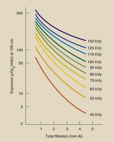
FIGURE 8-1 Nomogram for estimating the intensity of x-ray beams. From the position on the x-axis corresponding to the filtration of the imaging system, draw a vertical line until it intersects with the appropriate voltage (kVp). A horizontal line from that point will intersect the y-axis at the approximate x-ray intensity for the imaging system. (Courtesy Edward McCullough, University of Wisconsin.)
Factors That Affect X-ray Quantity
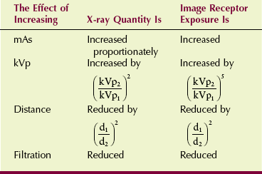
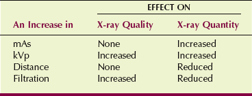
A number of factors affect x-ray quantity. Most are discussed briefly in Chapter 7; consequently, this section may serve primarily as a review. The factors that affect x-ray quantity affect exposure of the image receptor similarly. These relationships are summarized in Table 8-1.
Milliampere Seconds (mAs)
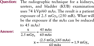
X-ray quantity is directly proportional to the mAs. When mAs is doubled, the number of electrons striking the tube target is doubled, and therefore the number of x-rays emitted is doubled.

 Remember that mAs is just a measure of the total number of electrons that travel from cathode to anode to produce x-rays.
where C (coulomb) is a measure of electrostatic charges and 1 C = 6.25 × 10¹⁸ electrons.
Kilovolt Peak (kVp)
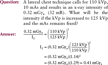
X-ray quantity varies rapidly with changes in kVp. The change in x-ray quantity is proportional to the square of the ratio of the kVp; in other words, if kVp were doubled, the x-ray intensity would increase by a factor of 4. Mathematically, this is expressed as follows:
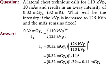
In practice, a slightly different situation prevails. Radiographic technique factors must be selected from a relatively narrow range of values, from approximately 40 to 150 kVp. Theoretically, doubling the x-ray intensity by kVp manipulation alone requires an increase of 40% in kVp.
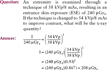
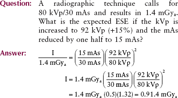
This relationship is not adopted clinically because as kVp is increased, the penetrability of the x-ray beam is increased, and relatively fewer x-rays are absorbed in the patient. More x-rays go through the patient and interact with the image receptor. Consequently, to maintain a constant exposure of the image receptor, an increase of 15% in kVp should be accompanied by a reduction of one half in mAs.
Note that by increasing kVp and reducing mAs so that image receptor exposure remains constant, the patient dose is reduced significantly. The disadvantage of such a technique adjustment is reduced image contrast when screen film is the image receptor. There is no change in contrast when using digital image receptors.
Distance
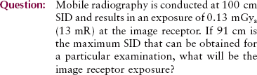
X-ray intensity varies inversely with the square of the distance from the x-ray tube target. This relationship is known as the inverse square law (see Chapter 3).
X-ray Quantity and Distance

where I1 and I2 are the x-ray intensities at distances d1 and d2, respectively.
 When SID is increased, mAs must be increased by SID2 to maintain constant exposure to the image receptor.
Compensating for a change in SID by changing mAs by the factor SID2 is known as the square law, a corollary to the inverse square law.
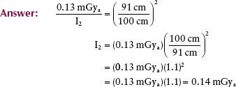
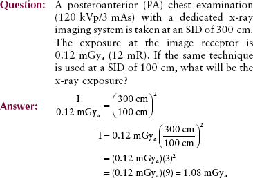
In practical terms, this can be rewritten as follows:
Filtration
X-ray imaging systems have metal filters, usually 1 to 5 mm of aluminum (Al), positioned in the useful beam. The purpose of these filters is to reduce the number of low-energy x-rays.
Low-energy x-rays contribute nothing useful to the image. They only increase the patient dose unnecessarily because they are absorbed in superficial tissues and do not penetrate to reach the image receptor.
When filtration is added to the x-ray beam, patient dose is reduced because fewer low-energy x-rays are found in the useful beam. Calculation of the reduction in exposure requires knowledge of half-value layer (HVL), which is discussed in the following section.
An estimate of exposure reduction can be made from the nomogram in Figure 8-1, where it is shown that the reduction is not proportional to the thickness of the added filter but is related in a complex way. The disadvantage of x-ray beam filtration can be reduced image contrast when using screen film caused by x-ray beam hardening. X-ray beam hardening increases the number of high energy x-rays in the beam by removing the lower-energy nonpenetrating x-rays.
X-Ray Quality
As the energy of an x-ray beam is increased, the penetrability is also increased. Penetrability refers to the ability of x-rays to penetrate deeper in tissue. High-energy x-rays are able to penetrate tissue more deeply than low-energy x-rays.
The penetrability of an x-ray beam is called the x-ray quality. X-rays with high penetrability are termed high-quality x-rays. Those with low penetrability are low-quality x-rays.
Factors that affect x-ray beam quality also influence radiographic contrast when screen film is the image receptor. Distance and mAs do not affect radiation quality; they do affect radiation quantity.
Half-Value Layer
Although x-rays are attenuated exponentially, high-energy x-rays are more penetrating than low-energy x-rays. Whereas 100-keV x-rays are attenuated at the rate of approximately 3%/cm of soft tissue, 10-keV x-rays are attenuated at approximately 15%/cm of soft tissue. X-rays of any given energy are more penetrating in material of low atomic number than in material of high atomic number.
In radiography, the quality of x-rays is measured by the HVL. Therefore, the HVL is a characteristic of the useful x-ray beam. A diagnostic x-ray beam usually has an HVL in the range of 3 to 5 mm Al or 3 to 6 cm of soft tissue.
The HVL of an x-ray beam is the thickness of absorbing material necessary to reduce the x-ray intensity to half of its original value.
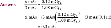
The HVL is determined experimentally, with a setup similar to that shown in Figure 8-2. This setup consists of three principal parts: the x-ray tube; a radiation detector; and graded thicknesses of filters, usually Al.
First, a radiation measurement is made with no filter between the x-ray tube and the radiation detector. Then, measurements of radiation intensity are made for successively thicker sections of filter. The thickness of filtration that reduces the x-ray intensity to half of its original value is the HVL.
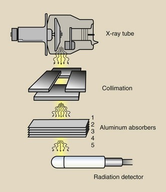
Several methods can be used to determine the HVL of an x-ray beam. Perhaps the most straightforward way is to graph the results of x-ray intensity measurements made with an experimental setup, like that in Figure 8-2. The graph in Figure 8-3 and the boxed graph below it show how this can be done when the following steps are completed.
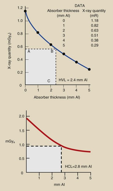
FIGURE 8-3 Data in the table are typical for half-value layer (HVL) determination. The plot of these data shows an HVL of 2.4 mm Al.
Steps to Determine the Half-Value Layer
1. Determine the x-ray beam intensity with no absorbing material in the beam and then with different known thicknesses of an absorber.
2. Plot the ordered pairs of data (thickness of absorber, x-ray quantity).
3. Determine the x-ray quantity equal to half the original quantity and locate this value on the y- or vertical axis of the graph in Figure 8-3.
4. Draw a horizontal line parallel to the x-axis from point A in step 3 until it intersects the curve (B).
5. From point B, drop a vertical line to the x-axis.
6. On the x-axis, read the thickness of the absorber required to reduce the x-ray intensity to half of its original value point (C). This is the HVL.
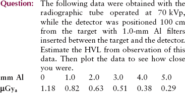
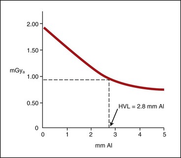
| Question: | The following boxed graph was plotted from measurements designed to estimate HVL. What does this graph suggest the HVL to be? |
| Answer: | At zero filtration, x-ray quantity appears to be approximately 1.9 mGya. One half of 1.9 mGya is 0.95 mGya. At the level of 0.95 mGya, a horizontal line is drawn from the y-axis until it intersects the plotted curve. From that intersection, a vertical line is dropped to the x-axis, where it intersects at 2.8 mm Al, the HVL. |
X-ray beam penetrability changes in a complex way with variations in kVp and filtration. Different combinations of added filtration and kVp can result in the same x-ray beam HVL. For example, measurements may show that a single x-ray imaging system has the same HVL when operated at 90 kVp with 2-mm Al total filtration as when operated at 70 kVp with 4-mm Al total filtration. In this case, x-ray penetrability remains constant, as does the HVL.
Factors That Affect X-ray Quality
Some of the factors that affect x-ray quantity have no effect on x-ray quality. Other factors affect both x-ray quantity and quality. These relationships are summarized in Table 8-2.
Kilovolt Peak (kVp)
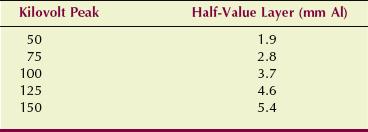
As the kVp is increased, so is x-ray beam quality and therefore the HVL. An increase in kVp results in a shift of the x-ray emission spectrum toward the high-energy side, indicating an increase in the effective energy of the beam. The result is a more penetrating x-ray beam.
Table 8-3 shows the measured change in HVL as kVp is increased from 50 to 150 kVp for a representative x-ray imaging system. The total filtration of the beam is 2.5 mm of Al.
Filtration
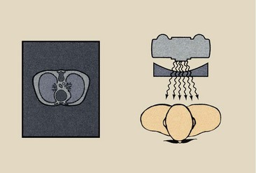
The primary purpose of adding filtration to an x-ray beam is to remove selectively low-energy x-rays that have little chance of getting to the image receptor. Figure 8-4 shows the emission spectrum of an unfiltered x-ray beam and an x-ray beam with normal filtration.
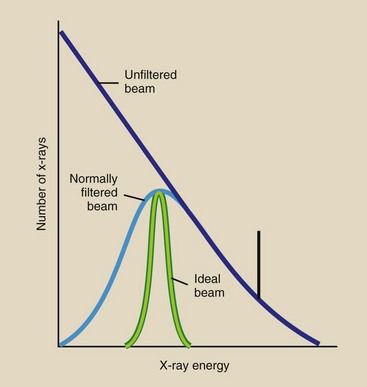
FIGURE 8-4 Filtration is used selectively to remove low-energy x-rays from the useful beam. Ideal filtration would remove all low-energy x-rays.
The ideally filtered x-ray beam would be monoenergetic because such a beam would further reduce the patient dose. It is desirable to remove totally all x-rays below a certain energy determined by the type of x-ray examination. To improve image contrast, it is also desirable to remove x-rays with energies above a certain level. Unfortunately, such removal of regions of an x-ray beam is not normally possible.
Almost any material could serve as an x-ray filter. Al (Z = 13) is chosen because it is efficient in removing low-energy x-rays through the photoelectric effect and because it is readily available, inexpensive, and easily shaped. Copper (Z = 29), tin (Z = 50), gadolinium (Z = 64), and holmium (Z = 67) have been used sparingly in special situations. As filtration is increased, so is beam quality, but quantity is decreased.
Types of Filtration
Filtration of diagnostic x-ray beams has two components: inherent filtration and added filtration.
Inherent Filtration
The glass or metal enclosure of an x-ray tube filters the emitted x-ray beam. This type of filtration is called inherent filtration. Inspection of an x-ray tube reveals that the part of the glass or metal enclosure through which x-rays are emitted—the window—is very thin. This provides for low inherent filtration.
The inherent filtration of a general purpose x-ray tube is approximately 0.5 mm Al equivalent. With age, inherent filtration tends to increase because some of the tungsten metal of both the target and filament is vaporized and is deposited on the inside of the window.
Special-purpose tubes, such as those used in mammography, have very thin x-ray tube windows. They are sometimes made of beryllium (Z = 4) rather than glass and have an inherent filtration of approximately 0.1 mm Al.
Added Filtration
A thin sheet of Al positioned between the protective x-ray tube housing and the x-ray beam collimator is the usual form of added filtration.
The addition of a filter to an x-ray beam attenuates x-rays of all energies emitted, but it attenuates a greater number of low-energy x-rays than high-energy x-rays. This shifts the x-ray emission spectrum to the high-energy side, resulting in an x-ray beam with higher energy, greater penetrability, and better quality. The HVL increases, but the extent of increase in the HVL cannot be predicted even when the thickness of added filtration is known.
Because added filtration attenuates the x-ray beam, it affects x-ray quantity. This value can be predicted if the HVL of the beam is known. The addition of filtration equal to the beam HVL reduces the beam quantity to half its prefiltered value and results in a higher x-ray beam quality.
| Question: | An x-ray imaging system has an HVL of 2.2 mm Al. The exposure is 20 µGya/mAs (2 mR/mAs) at 100 cm SID. If 2.2 mm Al is added to the beam, what will be the x-ray exposure? |
| Answer: | This is an addition of one HVL; therefore, the x-ray exposure will be 10 µGya/mAs (1 mR/mAs). |
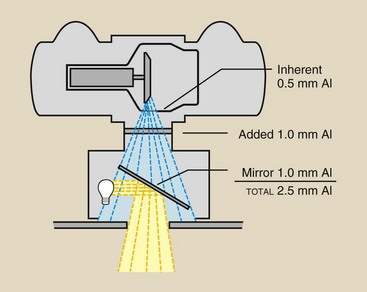
Added filtration usually has two sources. First, 1-mm or more sheets of Al are permanently installed in the port of the x-ray tube housing between the housing and the collimator.
With a conventional light-localizing variable-aperture collimator, the collimator contributes an additional 1 mm Al equivalent added filtration. This filtration results from the silver surface of the mirror in the collimator (Figure 8-5).
Compensating Filters
One of the most difficult tasks facing radiographers is producing an image with a uniform intensity when a body part is examined that varies greatly in thickness or tissue composition. When a filter is used in this fashion, it is called a compensating filter because it compensates for differences in subject radiopacity.
Compensating filters can be fabricated for many procedures; therefore, they come in various sizes and shapes. They are nearly always constructed of Al, but plastic materials also can be used. Figure 8-6 shows some common compensating filters.
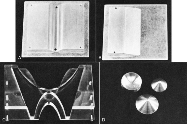
FIGURE 8-6 Compensating filters. A, Trough filter. B, Wedge filter. C, “Bow-tie” filter for use in computed tomography. D, Conic filters for use in digital fluoroscopy.
During film-screen PA chest radiography, for instance, if the left chest is relatively radiopaque because of fluid, consolidation, or mass, the image would appear with very low OD on the left side of the chest and very high OD on the right side of the chest. One could compensate for this OD variation by inserting a wedge filter so that the thin part of the wedge is positioned over the left side of the chest.
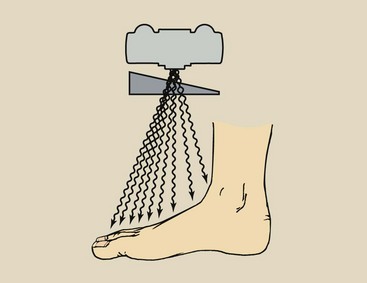
The wedge filter is principally used during radiography of a body part, such as the foot, that varies considerably in thickness (Figure 8-7). During an anteroposterior projection of the foot, the wedge would be positioned with its thick portion shadowing the toes and the thin portion toward the heel.
A bilateral wedge filter, or a trough filter, is sometimes used in chest radiography (Figure 8-8). The thin central region of the wedge is positioned over the mediastinum, and the lateral thick portions shadow the lung fields. The result is a screen-film radiograph with more uniform OD or a digital radiograph with more uniform signal intensity. Specialty compensating wedges of this type usually are used with dedicated apparatus, such as an x-ray imaging system used exclusively for chest radiography.
Special “bow-tie”–shaped filters are used with computed tomography imaging systems to compensate for the shape of the head or body. Conic filters, either concave or convex, find application in digital fluoroscopy, in which the image receptor, the image intensifier tube, is round.
A step-wedge filter is an adaptation of the wedge filter (Figure 8-9). It is used in some interventional radiology procedures, usually when long sections of the anatomy are imaged with the use of two or three separate image receptors.
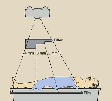
FIGURE 8-9 Arrangement of apparatus with the use of an aluminum step-wedge for serial radiography of the abdomen and lower extremities.
A common application of a step-wedge filter involves a three-step Al wedge and three 35 × 43-cm (14 × 17-in) image receptors for translumbar and femoral arteriography and venography. These procedures call for careful selection of radiographic technique.
Compensating filters are useful for maintaining image quality. They are not radiation protection devices.
Summary
Radiation quantity is the number of x-rays in the useful beam. Factors that affect radiation quantity include the following:
• mAs: X-ray quantity is directly proportional to mAs.
• kVp: X-ray quantity is proportional to the square of the kVp.
• Distance: X-ray quantity varies inversely with distance from the source.
• Filtration: X-ray quantity is reduced by filtration, which absorbs low-energy x-rays in the beam.
Radiation quality is the penetrating power of the x-ray beam. The penetrability is represented by the HVL, which is the thickness of additional filtration that reduces x-ray intensity to half its original value. Factors that affect x-ray beam penetrability or radiation quality include the following:
• kVp: X-ray penetrability is increased as kVp is increased.
• Filtration: X-ray penetrability is increased when filtration is added to the beam.
Following are the three types of filtration: (1) inherent filtration of the glass or metal enclosure; (2) added filtration in the form of Al sheets; and (3) compensating filters, which provide variation in intensity across the x-ray beam.
1. Define or otherwise identify the following:
d. A kVp change equal to twice the mAs
e. Three filter materials used with diagnostic x-ray beams
2. Graph the change in HVL with changing kVp (from 50 to 120 kVp) for an x-ray imaging system that has total filtration of 2.5 mm Al. Check your answer by plotting the data in Table 8-3.
3. An abdominal radiograph taken at 84 kVp, 150 mAs results in patient radiation exposure of 6.5 mGya. The image is too light and is repeated at 84 kVp, 250 mAs. What is the new radiation exposure?
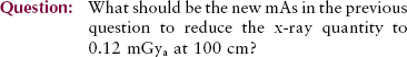
4. An image of the lateral skull taken at 68 kVp, 20 mAs has sufficient optical density but too much contrast. If the kVp is increased to 78 kVp, what should be the new mAs?
5. A chest radiograph taken at 180 cm SID results in an exposure of 120 µGya. What would the exposure be if the same radiographic factors were used at 100 cm SID?
6. The following data were obtained with a fluoroscopic x-ray tube operated at 80 kVp: The exposure levels were measured 50 cm above the patient couch with aluminum absorbers positioned on the surface of the couch. Estimate the HVL through visual inspection of the data; then plot the data and determine the precise value of the HVL.

7. When operated at 74 kVp, 100 mAs with 2.2 mm Al added filtration and 0.6 mm Al inherent filtration, the HVL of an x-ray imaging system is 3.2 mm Al and its output intensity at 100 cm SID is 3.5 mGya. How much additional filtration is necessary to reduce the x-ray intensity to 1.75 mGya?
8. The following technique factors have been shown to produce good-quality radiographs of the cervical spine with an x-ray imaging system that has 3 mm Al total filtration. Refer to Figure 8-1 and estimate the x-ray intensity at 100 cm SID for each.
9. A radiographic exposure is 80 kVp at 50 mAs. How many electrons will interact with the target?
10. An extremity is radiographed at 60 kVp, 10 mAs, resulting in an x-ray intensity of 280 µGya. If the technique is changed to 55 kVp, 10 mAs, what is the resultant x-ray intensity?
11. What is the square law, and how is it used?
12. What is the primary purpose of x-ray beam filtration?
13. The kVp is reduced from 78 to 68 kVp. What, if anything, should be done with mAs to maintain exposure of the image receptor constant?
14. What is the relationship between x-ray quantity and mAs?
16. List the two ways an x-ray beam can be shifted to a higher average energy.
17. Why is aluminum used for x-ray beam filtration?
18. Describe the use of a wedge filter during radiography of a foot.
19. Does adding filtration to the x-ray beam affect the quantity of x-rays reaching the image receptor?
20. Fill in the following chart:
| Increasing | Effect on X-ray Quality | Effect on X-ray Quantity |
| mAs | __________ | __________ |
| kVp | __________ | __________ |
| Distance | __________ | __________ |
| Filtration | __________ | __________ |
The answers to the Challenge Questions can be found by logging on to our website at http://evolve.elsevier. com.