Closed-Circuit Anesthesia
ANESTHESIA ADMINISTRATION AND MONITORING
MODEL-ASSISTED UNDERSTANDING OF CLOSED-CIRCUIT ANESTHESIA
CONTINUUM FROM HIGH-FLOW TO LOW-FLOW ANESTHESIA
LACK OF BUILDUP OF TOXIC SUBSTANCES
USING TODAY'S TECHNOLOGY: PRACTICALITIES
Principles
The basic principle of closed-circuit anesthesia is maintenance of a constant anesthetic state by adding gases and vapors to the breathing circuit at the same rate that the patient’s body removes those same substances. Often, the desired anesthetic state is first established using a high fresh gas flow (FGF) composed of gases, such as oxygen and nitrous oxide or air, and vapors (e.g., isoflurane, sevoflurane, desflurane). Once a steady state is attained, inspired and end-expired gas concentrations or tensions are noted, and FGF is reduced. Throughout this chapter, the words tension and partial pressure are used interchangeably. For gases, they have the same value as concentration. This is discussed under the section Partial Pressure. The circuit and patient gas tensions are maintained constant by adding oxygen, nitrous oxide, and agent vapor to the breathing circuit. In one common approach to closed-circuit maintenance, the amount of gas and vapor administered is determined empirically by titration. Several different titration endpoints can be used. Choices include maintenance of inspired tension, expired tension, and/or estimated anesthetic depth. When titrating against a defined endpoint, drugs can be added in a measured or quantified manner, or they can be added empirically without regard to the total amount administered. In closed-circuit anesthesia techniques, carbon dioxide is removed from exhaled gas, and the remaining exhaled gases and vapors are added to the FGF to produce inhaled gas. One advantage of this technique is that all gases exhaled are already warmed and humidified by the patient and are therefore well suited for rebreathing.1 Another advantage is that oxygen consumption is monitored by titration. A final advantage is that cost is reduced dramatically.
In closed-circuit and low-flow anesthesia, inhaled gas is formed from two sources, and exhaled gas forms most of what the patient will breathe. In addition to exhaled gas, fresh gas is added in the correct quantity and composition to achieve the inspired gas tensions desired. The same inspired and expired gas tensions are established with a closed circuit as with a semiclosed or open (nonrebreathing) circuit. In this chapter the terms open circuit and nonrebreathing circuit are used interchangeably.
Closed-Circuit Anesthesia
Closed-circuit anesthesia can be viewed in several different ways. From one perspective, it is an anesthetic technique unlike all others. The classical closed-circuit literature describes theory and practice different from other techniques. In the classic closed-circuit approach, once a stable level of anesthesia is established with high-flow oxygen, nitrous oxide, and volatile agent, FGF is reduced to the patient’s predicted oxygen consumption (243 mL/min for a 70-kg adult), predicted nitrous oxide uptake rate (approximately 100 mL/min after the first 30 min), and predicted inhaled agent uptake. Nitrous oxide and agent uptake rates are calculated according to a mathematical formula based on body weight.2
The traditional closed-circuit anesthesia literature uses anesthetic liquid injection or infusion rather than a vaporizer. Liquid agent is administered to the breathing circuit according to a prescribed time regimen.3-5 Specifically, the drug administration rate is inversely proportional to the square root of time (t):

This empiric relationship was first noted by Severinghaus6 for nitrous oxide in 1954 and was popularized by Lowe5 beginning in 1972. Severinghaus’s original data demonstrated that nitrous oxide uptake followed this power/function relationship fairly closely in the subjects he studied. Connor and Philip recently revalidated this mathematical relationship numerically7 and analytically.8
A scientific explanation exists for this curious and unexpected relationship. It has long been known that body tissues perfused with blood of a constant drug concentration or vapor tension have an uptake rate that decreases with time. Specifically, theory and research9 have demonstrated that uptake into each tissue takes the form of an exponential:

where t is time and τ is the time constant, or the time required to achieve 63% of the final value in response to a step input; e is the base of natural logarithms (2.7183 and so on), and K is a predictable constant. It can easily be derived that


where  equals the time required to achieve half the final value in response to a step input.
Total body uptake is the sum of the individual uptakes by each tissue. In this case, uptake is the sum of a group of exponentials of different amplitudes (Ktissue) and time constants (τtissue). The sum of these exponentials is approximately equal to the power function,  . It must be emphasized that the exponential relationship for a single tissue is derived theoretically and can be demonstrated empirically. But the power/function relationship is an empiric one that approximates the multiple exponential functions that describe the uptake into diverse tissues.7,8
Partial Pressure, Tension, and Concentration
Throughout this chapter, the words tension and partial pressure are used interchangeably. This physical variable represents the effective pressure exerted by a gas, whether it is in the gas phase alone, in combination with another gas, or dissolved in blood or tissue.
Partial pressure is expressed in percent of 1 atmosphere (1 atm = 760 mm Hg). Expressing partial pressure this way serves several purposes. When partial pressure is expressed as percent of 1 atm, partial pressure and concentration have the same numeric value for gases. For example, 1 vol% isoflurane has an isoflurane tension of 1% of 1 atm, an expression often shortened to 1%. For blood and tissues, partial pressure is also expressed as a percent. By this definition, a tissue anesthetic measure of 1% does not represent 1% concentration; rather, it represents a partial pressure of 1% of 1 atm or 1% times 760 mm Hg, or 7.6 mm Hg in terms of absolute pressure.
Next, when partial pressure is expressed as a percent of one standard atmosphere (i.e., 760 mm Hg), the numbers and concepts work equally well at any atmospheric pressure. This is because the physiologic effects of inhaled anesthetics are the result of partial pressure and not concentration.7,8 Thus, anesthetic tensions in the apparatus and patient are the variables that best explain kinetics in an understandable way.
When anesthetics are present in liquid or tissue, their concentrations are equal to their partial pressure × tissue/gas solubility × atmospheric pressure, according to Henry’s law. According to Dalton’s law, for multiple gases, this applies to each as if it were alone.
It is believed that the blood leaving each tissue compartment is in equilibrium with the tissues in that compartment, therefore the partial pressure in venous blood is equal to that in the tissues, as Graham’s law states. The blood entering each compartment has the same partial pressure of all gases as the arterial blood has everywhere. In the absence of lung shunt, arterial partial pressure equals alveolar partial pressure. Clinicians measure end-tidal (ET) gas concentrations or partial pressures. End-tidal partial pressure equals alveolar partial pressure when there is no physiologic dead space. After an infinite amount of time, the partial pressure of anesthetic inspired gas, alveolar gas, arterial blood, all tissues, and all venous blood, including mixed venous blood, is equal. At this time, there is no blood uptake of anesthetic at all. Thus the inspired and expired partial pressures are equal as well. Thus, after an infinite amount of time, the partial pressure of anesthetic throughout the system, from vaporizer to all tissues, is the same.
The above paragraph is a simplification that serves well in most situations. Exploring this further, in the presence of lung shunt, arterial tension is closer to mixed venous tension than it would be otherwise. When physiologic dead space is present, some of the gas leaving the lungs is inspired gas, rather than alveolar gas. This makes end-tidal partial pressure closer to inspired partial pressure than it would otherwise be. These are temporary limitations. After an infinite amount of time, these effects disappear as well, and anesthetic tension is equal everywhere. Because the alive body continues to consume oxygen and produce carbon dioxide, this equalization does not occur with these gases.
Lowe Technique
In the classic Lowe2 technique for closed-circuit anesthesia, a loading dose of anesthetic vapor is administered to the breathing circuit to bring circuit tension to that desired in the patient’s alveoli. This level is somewhat higher than in the inspired gas. A unit dose for maintenance is then selected according to the patient’s body weight and is proportional to body mass to the three-quarter power (kg3/4), a relationship first shown by Kleiber10 that has been further described by Brody.11 Kleiber’s law goes on to state that many parameters of metabolic and circulatory processes—oxygen consumption, carbon dioxide production, cardiac output, and daily liquid requirement—are proportional to body mass raised to the three-quarter power.
In Lowe’s classic closed-circuit anesthesia, unit doses are administered at specific times with intervals between administrations increasing with time. These intervals, in minutes, are the sequence of odd integers {1, 3, 5, 7, 9, …} This results in injections being made at 0, 1, 4, 9, 16, and 25 minutes. This is referred to as the square root of time model, in that these injection times are the series of numbers whose square roots are sequential integers. This strange number manipulation may seem farfetched; however, Connor and Philip7,8 demonstrated that this relationship approximated the uptake of nitrous oxide shown by Severinghaus6 with remarkable accuracy.
Even closed-circuit enthusiasts advise care and careful observation of the patient, as always. Lowe recommended that after 25 minutes, the square root of time method should be modified, and that the intervals between injections should not be lengthened as much (Lowe, personal communication, 1979). This is because after 25 minutes of anesthetic at constant depth, the rate of uptake becomes almost constant. By this time, fast (vessel-rich) tissues have equilibrated with arterial blood. Meanwhile, uptake into muscle and fat are diminishing slowly, more slowly than the square root of time, because of their long time constants.
It must be noted that the original 1972 theory and “cookbook” for closed-circuit anesthesia was written during the era of more primitive measurement and analysis (in 1972, the digital pocket calculator had not yet replaced the analog slide rule). Anesthetic agent analysis was uncommon, and the only clinically available device was the Dräger Narkotest (Dräger Medical, Telford, PA), which consisted of a slowly responding silicone rubber band in a box connected to a mechanical indicator.12 The “rubber band in a box” stretched in proportion to the potency of the single or combined inhalation anesthetic tensions administered.
With each administration technique—open circuit, semiclosed circuit with high flow, semiclosed circuit with low flow, closed circuit with vaporizer, and closed circuit with liquid injection—each patient’s inspired, end-expired, and alveolar anesthetic tensions are the same and are independent of administration technique. Thus from the patient’s viewpoint, all inhalation anesthetic administration techniques are equivalent. The only difference is in the way the drugs are administered and the resulting waste or lack thereof.
Although the conventional closed-circuit literature used models created by fitting experimental data to particular mathematical formulations, this chapter does not rely on these. Rather it assumes that an anesthetic agent monitor is available and in use, measuring inspired and expired anesthetic concentrations. The dosage administration scheme is adjusted on the basis of a patient’s measured and needed levels of inspired and expired vapor and nitrous oxide. Delivered oxygen flow is adjusted similarly. In the absence of a multigas monitor, closed-circuit anesthesia may still be employed, but greater vigilance and understanding of anesthetic depth and uptake of anesthetic and oxygen are required.
Anesthesia Administration and Monitoring
Truly closed-circuit anesthesia cannot always be performed because of technical limitations of our gas delivery systems or gas monitors. In the 1980s, gas monitoring was often performed with a multiplexed mass spectrometer shared by 16 or 31 ORs, monitoring these rooms in succession. In that situation, sampled gas could not be returned to the patient from whom it was sampled. With the advent and commonality of stand-alone or integrated gas monitors with anesthesia delivery systems, there should be no such impediment. However, sampled gas return requires specific approval and is not available with anesthesia gas monitors by GE Healthcare (Waukesha, WI).
In 1963, Eger13 introduced the concept of anesthesia at constant alveolar concentration and defined the term minimum alveolar concentration (MAC). As a foundation for his approach, he used the pharmacokinetic theory explained by Seymour Kety14,15 in 1950. Eger showed that constant alveolar concentration or tension can be produced and maintained when inspired anesthetic concentration is adjusted properly. To compute the proper adjustment sequence, or continuum, he calculated anesthetic uptake into each organ group and adjusted inspired concentration to maintain alveolar concentration constant. Figure 26-1 shows the inspired concentration required to maintain 0.8% alveolar halothane, equal to 1 MAC.13 Inspired halothane concentration is begun at 3.3% and is slowly and continuously reduced to 2% at 5 minutes, 1.5% at 20 minutes, and 1% at 3 hours.
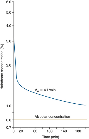
FIGURE 26-1 Inspired concentration required to maintain 0.8% alveolar halothane. Halothane inspired concentration begins at 3.3% and is slowly and continuously decreased to 2% at 5 minutes, 1.5% at 20 minutes, and 1% at 3 hours. VA, alveolar ventilation. (From Eger EI II, Guadagni NP: Halothane uptake in man at constant alveolar concentration. Anesthesiology 1963; 24:299-304.)
A more realistic clinical endpoint is constant or desired anesthetic tension in the site of interest, the target organ, the brain, and the spinal cord. Producing a stepped or controlled change in brain anesthetic tension from its current level to any desired level is a useful clinical objective. This is equally true for high-flow, low-flow, and closed-circuit anesthesia.
Anesthesia Assessment and Adjustment
To the clinician who has used halothane, Eger’s calculated time course of halothane administration is quite reasonable. It mimics what was administered to many patients. Of course, in today’s clinical practice, the vaporizer is not adjusted according to the clock. Rather, the patient’s depth of anesthesia is assessed by mental integration of many signs. The pupils are observed for dilation or constriction; and blood pressure, heart rate, and possibly processed electroencephalogram (EEG; e.g., bispectral index, patient state index, entropy) and other variables are measured and evaluated. With the convenient availability of anesthetic agent monitors, most clinicians monitor expired anesthetic concentration (tension) as an important additional sign. This represents the anesthetic level in the end-expired gas as an approximation to that in the alveoli as an approximation to that in the blood. In the best of all situations, where end-tidal equals alveolar and arterial tension, the brain delay is still 3 to 5 minutes. This means that the measured end-tidal value predicts what the brain concentration will be in the near future. Likewise, view of the end-tidal value a few minutes previous is a real-time indicator of the brain and spinal cord values.
To achieve the “ideal” anesthetic, vaporizer setting and FGF are adjusted to maintain constant brain anesthetic tension. This is done by allowing a reasonable amount of alveolar overpressure during the period when anesthesia is being deepened (described later in this chapter). Finally, an estimate or measure of depth of anesthesia can be used.
High and Low Flows
Eger’s example (see Fig. 26-1) demonstrates anesthesia administration with a perfect nonrebreathing circuit (open circuit). In that system, inspired concentration is perfectly controlled. In contrast, a semiclosed breathing circuit with a carbon dioxide absorber is the one most commonly used around the world. With this circuit, inspired concentration or tension is dependent on FGF and vaporizer setting as well as by exhaled ventilatory flow and exhaled agent tension.
Figure 26-2 shows the semiclosed circuit vaporizer settings required for constant alveolar tension of 0.8% halothane at various FGFs as calculated by Eger.13 As FGF into the semiclosed circuit is progressively decreased from 8 L/min to 1 L/min, vaporizer setting, and hence tension delivered to the breathing circuit, must be increased. This again is because inspired gas is a mixture of fresh gas from the anesthesia machine and gas exhaled from the patient. As FGF is decreased, a relatively higher fraction of exhaled gas is rebreathed. Because exhaled gas usually has a lower anesthetic tension than inspired gas, higher vaporizer settings are required to achieve the same inspired tension.
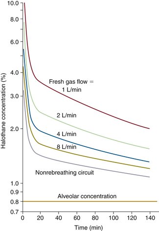
FIGURE 26-2 Semiclosed circuit vaporizer settings required for constant alveolar tension of 0.8% halothane at various fresh gas flows as calculated by Eger. (From Eger EI II, Guadagni NP: Halothane uptake in man at constant alveolar concentration. Anesthesiology 1963; 24:299-304.)
Note that at 1 L/min of FGF, the initial halothane vaporizer setting is more than 10%. This is difficult, if not impossible, to achieve with modern anesthesia delivery systems, because the vaporizer cannot deliver that high a concentration. It must be emphasized that the high concentration of anesthetic is delivered to the breathing circuit, where it mixes with the 0.8% in the patient’s exhaled gas to produce an inspired concentration that must be the same 3.3% as was required in an open circuit. In the two cases, the time course of anesthesia induction is identical, because inspired anesthetic concentration is the same. The patient’s body is not aware of how the anesthesiologist created the gas mixture breathed.
Nonrebreathing (Open-Circuit) and Closed-Circuit Anesthesia
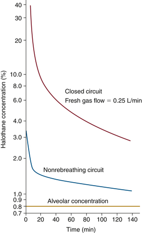
Figure 26-3 shows vaporizer settings required to maintain constant alveolar tension for a nonrebreathing circuit (open circuit) and a completely closed circuit with an FGF of 0.25 L/min. With the closed circuit, the initial vaporizer setting is 40% halothane. In practice, this is impossible for several reasons. First, modern concentration-calibrated vaporizers can be set to administer no more than 5% halothane. Second, the vapor pressure of halothane at room temperature is only 0.33 atm (33%, or 243 mm Hg), thus 40% halothane cannot exist under these conditions. Nonetheless, 40% is the theoretical concentration required. This high concentration at the low FGF of 250 mL/min into a closed circuit produces the same 3.3% inspired concentration that will achieve the same 1 MAC (0.8% end-expired) anesthetic.
Liquid Injection Anesthesia
As discussed, 1 MAC anesthesia can be attained and maintained with a wide range of FGFs and required high-range of vaporizer settings. It also can be approximated with sequential injections of anesthetic liquid into the breathing circuit. In closed-circuit liquid injection anesthesia, the same inspired and expired tensions are desired. Because the liquid injection is in multiple boluses, the time course of inspired and expired tension is not as smooth. However, the brain’s 3 minute time constant tends to provide constant anesthetic depth even with sequential liquid injections. The advantage of liquid injection is that the concentration limitation of the vaporizer can be overcome.
Some closed-circuit enthusiasts choose to inject liquid anesthetic into the breathing circuit with a syringe pump. For this technique to work, the same overall administration rate must be maintained as with closed-circuit liquid bolus injection. The earlier-described square-root-of-time model is still used, but the injection rate is adjusted to administer unit doses over successively longer time periods.
Model-Assisted Understanding of Closed-Circuit Anesthesia
Gas Man (Med Man Simulations, Chestnut Hill, MA) is an educational computer program (www.gasmanweb.com/index.html)16 designed to teach the pharmacokinetics of inhalation anesthetics. It has been shown to be an effective educational tool17 and has been used to demonstrate various aspects of inhaled agent kinetics18 and has been shown to be accurate.19 Various models have been previously described to explain uptake and distribution,20-23 and other programs are also available.24
The Gas Man picture represents the inhalation kinetics uptake and distribution models in schematic form and provides a static snapshot of the anesthetic tensions in body tissues (compartments). The Gas Man graph shows the time course of anesthetic tension in each compartment.
Figure 26-4 shows an annotated Gas Man picture (top) and Gas Man graph (bottom), which represent the time course and current state of the patient and breathing circuit after 15 minutes; here, it is at the end of 5% isoflurane anesthesia. The picture shows anesthetic tension in various locations of interest as well as flows that conduct drugs from compartment to compartment. Compartments are filled to heights that represent their respective partial pressures. In the equilibrium state, all compartments would become filled to the same height, because their partial pressures are equal.
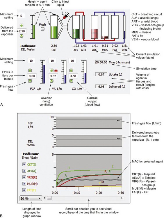
FIGURE 26-4 Annotated Gas Man picture and graph (Med Man Simulations, Chestnut Hill, MA). A, The picture shows the current state; compartments are filled to heights that represent their respective partial pressures. B, Annotated graph shows the 30-minute time course of anesthesia. MAC, minimum alveolar concentration.
In the graph of Figure 26-4 (bottom) it is apparent that tissues in the vessel-rich group rapidly equilibrate with and almost equal arterial anesthetic tension. Muscle and fat equilibrate more slowly. The anesthetic tension in mixed venous blood returning to the heart is dominated by blood coming from the vessel-rich group, which receives and returns 75% of the cardiac output. Muscle receives 20% and fat receives 5% of cardiac output, respectively. Anesthetic returning to the patient’s alveoli is then either exhaled to the breathing circuit or recirculated to arterial blood according to the relationship between alveolar ventilation and cardiac output. Although this simple description of the Gas Man oversimplifies the situation, it is sufficient to explain both qualitative and quantitative aspects of inhalation anesthesia.
In addition to displaying the flow between compartments, Figure 26-4, B, provides additional information about simulation time, patient uptake of anesthetic, and quantity of anesthetic delivered to the breathing circuit. At the end of 15 simulated minutes, anesthetic uptake is 0.9 L isoflurane vapor, and volume delivered to the breathing circuit is 6.0 L. The difference between these two values, 5.1 L, is the volume discarded from the breathing circuit through the exhaust valve during the 15 minutes of anesthetic administration plus that which remains in the circuit. Efficiency is defined as the ratio of uptake to delivered quantities, expressed as a percent. Here, efficiency equals 0.9 L uptake divided by 6.0 L delivered, which equals 0.15, or 15%. It should be noted that 5.1 L (85%) of the nitrous oxide–oxygen–isoflurane mixture is discarded. This gas is collected by the waste anesthetic gas system in the OR, conducted to the hospital chimney, and released to the atmosphere.
The above example shows how the Gas Man screens can be interpreted. Furthermore, it shows the breathing circuit response to a constant vaporizer setting and a high FGF. This administration technique mimics what is clinically achieved when an attempt is made to provide constant inspired tension using a semiclosed circle system at high FGFs. Anesthesia, however, is not normally administered with a constant vaporizer setting or constant inspired tension. Rather, the trained clinician attempts to maintain anesthesia depth appropriate for surgical conditions by adjusting the vaporizer settings. This is done by observing the response of the patient’s clinical signs and by interpreting whatever quantitative measurements are available. Although blood pressure and EEG measures and the like may be useful, there is at present no reliable quantified measure of anesthesia depth.
In an attempt to maintain constant anesthesia depth, constant anesthetic tension in the alveoli is a reasonable objective, and end-expired anesthetic tension or concentration is a good measure of alveolar tension.13,25 The specific measurable objective in administering anesthesia with constant depth then is to maintain a constant end-expired anesthetic tension; this is now a quantifiable and achievable objective, accomplished by adjusting the vaporizer in whatever manner is required while observing the anesthetic agent monitor that displays inspired and end-expired anesthetic tensions.
Continuum from High-Flow to Low-Flow Anesthesia
The continuum from high-flow to low-flow anesthesia can also be well explained by the Gas Man model and simulation. Figure 26-5 shows the picture and graph representing constant alveolar tension for halothane administered with an open (nonrebreathing) circuit for 15 minutes. The inspired (equal to delivered for the open circuit) halothane tension is initially set to 3.3% and then gradually reduced to produce a flat alveolar tension curve. When this is done carefully, the time course of vaporizer setting and expired anesthetic tension or concentration is indistinguishable from that seen in Eger’s example (Fig. 26-1).
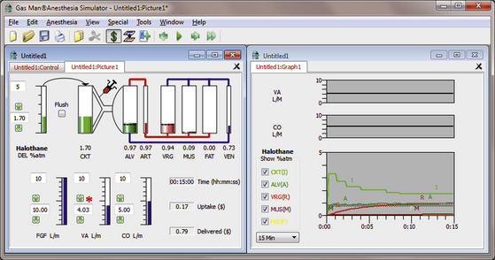
FIGURE 26-5 Open-circuit constant alveolar halothane anesthetic. The Gas Man picture and graph (Med Man Simulations, Chestnut Hill, MA) show constant alveolar tension achieved and maintained with an open (nonrebreathing) circuit and careful adjustment of the vaporizer setting.
Notice that in the Gas Man picture, after 15 minutes of anesthesia, the cumulative patient uptake of anesthetic is 0.6 L of halothane vapor. The volume of halothane delivered to the breathing circuit is 2.7 L, computed as if the FGF were 10 L/min. Also, the upper half of the Gas Man graph shows alveolar ventilation and cardiac output; delivered tension and FGF are not relevant to an open circuit. Delivered tension and FGF are displayed in this location when a semiclosed or closed system technique is simulated.
Figure 26-6 shows the picture and graph of isoflurane administered at constant alveolar isoflurane tension (1 MAC = 1.1%) achieved and maintained by appropriate vaporizer adjustment in a nonrebreathing (open) circuit. Initial inspired isoflurane tension is 2.9%, tapered to 1.5% after 15 minutes.
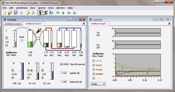
FIGURE 26-6 Isoflurane open-circuit constant alveolar anesthetic tension. The Gas Man picture and graph (Med Man Simulations, Chestnut Hill, MA) show constant alveolar isoflurane tension achieved and maintained with an open (nonrebreathing) circuit and careful vaporizer adjustment. Note the relative similarity to the halothane open-circuit curve in Figure 26-5.
It was noted earlier that alveolar overpressure—that is, alveolar tension transiently above 1.0 MAC—is sometimes used to produce a more rapid increase in anesthetic tension in the vessel-rich tissue group (VRG), which includes the brain, spinal cord, and other fast organs (kidneys, liver, spleen). The VRG includes the target organ, the patient’s brain and spinal cord; this anesthetic tension is termed VRG. Only a brief period of overpressure is required, because VRG rapidly equalizes with arterial tension, which should by this time have fallen to the desired level. A common target for anesthesia in the brain is 1 MAC; another is 1.3 MAC.
Figure 26-7 shows the picture and graph of isoflurane administered at constant VRG isoflurane tension (1 MAC = 1.1%) achieved and maintained by appropriate vaporizer adjustment in a nonrebreathing (open) circuit. Initial inspired isoflurane tension is 5.0%, tapered to 1.5% after 15 minutes. Alveolar tension rises to about 2 MAC for about 2 minutes.
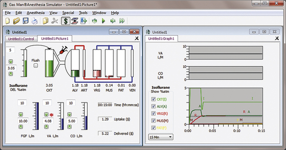
FIGURE 26-7 Constant brain anesthetic tension achieved with an open circuit administering isoflurane. The Gas Man picture and graph (Med Man Simulations, Chestnut Hill, MA) show constant brain tension achieved and maintained with an open (nonrebreathing) circuit and careful vaporizer adjustment.
Figure 26-8 shows the picture and graph depicting constant brain isoflurane tension (1 MAC = 1.1%) achieved in a semiclosed circuit with an FGF of 10 L/min. The anesthetic tension delivered to the breathing circuit (DEL) begins at 5% isoflurane and is reduced to achieve and maintain a constant VRG tension of 1.1%. Just as with the open circuit, it is observed that inspired tension (I) begins at 2.9% and is reduced to approximately 1.5% at the end of 15 minutes. Alveolar tension rises to about 1.6% for about 3 minutes. Constant VRG tension is achieved with 3.3 L of vapor delivered to the breathing circuit, and the patient’s tissue uptake is 0.4 L of vapor. The efficiency is thus about 12% (efficiency = 0.4 L uptake/3.3 L delivered, or 12.1%) Hence, in the common high-flow clinical situation, more than 80% of the anesthetic agent delivered to the breathing circuit is wasted.
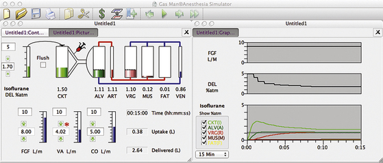
FIGURE 26-8 High-flow semiclosed circuit. Gas Man picture and graph (Med Man Simulations, Chestnut Hill, MA) of constant alveolar isoflurane tension achieved and maintained with a high-flow semiclosed circuit with a fresh gas flow of 8 L/min.
Figure 26-9 shows a trend graph of airway anesthetic tension obtained during a high-flow induction with isoflurane, measured with an infrared agent analyzer. Inspired and end-tidal isoflurane tensions are represented by the upper and lower edges of the graph. The isoflurane vaporizer is set to 3%, 2.5%, and 2.2% at 0, 1, and 2 minutes, respectively. Note that constant alveolar anesthetic tension is achieved and maintained after the 3-minute “wash-in” of the patient’s lungs.
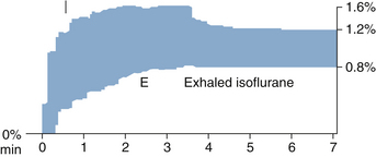
FIGURE 26-9 Constant expired anesthetic tension shown on trend from multigas monitor. The graph shows the time course of airway anesthetic tension with the upper and lower edges representing inspired (I) and end-expired (E) isoflurane tensions.
Low-Flow Anesthesia
Use of the breathing circuit can be carried one step further. Instead of decreasing the vaporizer setting, FGF can be reduced to achieve the same decreasing inspired tension; Figure 26-10 shows this. FGF begins at 8 L/min while the vaporizer is set to 5% isoflurane (DEL). At the end of 2 minutes, rather than decreasing the vaporizer setting, FGF is decreased to 2 L/min. Then, several minutes later, the vaporizer setting (DEL) is decreased as needed. All adjustments are made while the alveolar anesthetic tension (A, dark green) is observed, and the FGF vaporizer setting is adjusted to achieve 1.1% (1 MAC) expired isoflurane. At the end of 15 minutes with this low-flow anesthetic technique, 1.2 L has been delivered to the breathing circuit, and uptake by the patient’s tissues is 0.6 L. This anesthetic administration is then 33% efficient in terms of use of isoflurane vapor (i.e., 0.4/1.2 = 0.333). In other words, with the low-flow technique, the concentration inspired by the patient is identical to that inspired with the high-flow technique; patient response—end-expired anesthetic tension, alveolar tension, and anesthesia depth—are also unaffected. The only difference between the two techniques is the manner in which the appropriate gas mixture is created.
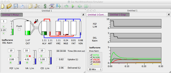
FIGURE 26-10 Low-flow semiclosed circuit. Constant (1 MAC) alveolar isoflurane tension is achieved and maintained with a semiclosed circuit. First, high fresh gas flow ([FGF] 8 L/min) is used for 2 minutes. FGF is then reduced to 2 L/min (moderately low flow), and the vaporizer setting is reduced as needed to maintain a constant end-expired tension.
Closed-Circuit Anesthesia
FGF can be reduced to its minimum, thus achieving a completely closed circuit. Figure 26-11 illustrates this in schematic form. In the closed-circuit anesthesia technique, FGF is set equal to the patient’s uptake of each and every gas used, including oxygen. When this is achieved, total volume is constant, and the concentration and tension of each substance is constant.
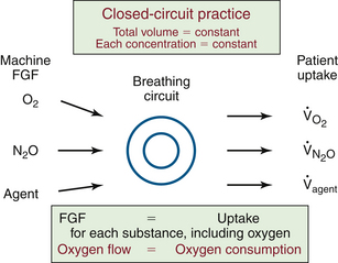
FIGURE 26-11 The fundamental principle of closed-circuit anesthesia. Fresh-gas flow (FGF) to the breathing circuit is equal to the patient’s uptake for each and every gas and vapor. As a result, the total volume is constant, and the concentration and tension (partial pressure) of each gas are constant. The patient’s oxygen consumption can be estimated from the oxygen flow to the closed circuit.
Oxygen uptake, usually referred to as oxygen consumption, is a particularly interesting result obtained using a closed circuit. The patient’s oxygen consumption is equal to the flow of oxygen to the closed circuit. This equality is maintained by careful adjustment of oxygen flow.
Liquid Injection
To achieve closed-circuit anesthesia beginning with induction, or to accomplish rapid deepening during anesthesia, a modern concentration-calibrated, direct-reading vaporizer will not suffice. This is because the volume of its output at low FGF is insufficient to produce large or rapid changes in inspired tension. For this reason, liquid anesthetic agent is injected directly into the breathing circuit by many practitioners of the closed-circuit technique. The Gas Man model allows liquid injection to be simulated, while the student observes the resulting anesthetic tensions in the circuit and in the patient. Other practitioners increase FGF whenever they desire to change depth.
Figure 26-12 shows a Gas Man representation of closed-circuit anesthesia administered with 0.5 mL liquid isoflurane injections timed to achieve and maintain 1.1% exhaled anesthetic partial pressure. Each 0.5 mL of liquid isoflurane generates approximately 100 mL of vapor at room temperature. Liquid isoflurane is injected at empiric times with the objective of maintaining 1.1% alveolar partial pressure. Note that although inspired tension changes dramatically, and expired tension varies somewhat, brain tension (VRG on the picture, brown [R] on the graph) is quite stable over time. Alveolar tension can be smoothed by decreasing the liquid bolus volume and increasing the frequency of injection by converting to a continuous infusion of liquid anesthetic into the breathing circuit.
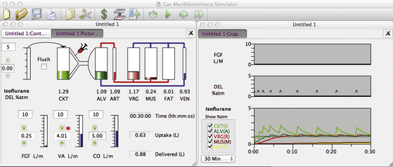
FIGURE 26-12 Closed circuit with 0.5 mL injections of liquid isoflurane timed empirically from Gas Man (Med Man Simulations, Boston, MA). Each time alveolar tension fell to 1.0 %, a 0.5 mL injection of isoflurane was made in the Gas Man model.
At the end of 30 minutes of empiric intermittent liquid injection, the graph in Figure 26-12 shows that patient uptake is again 0.6 L of isoflurane vapor. To achieve this, 0.9 L of vapor was delivered to the breathing circuit as nine individual 0.5 mL liquid injections. The discrepancy between the 0.9 L delivered and the 0.6 L uptake is anesthetic vapor that remains in the breathing circuit (CKT, 5 L) and the patient’s lungs (ALV, 2 L). This same 0.3 L volume of anesthetic vapor was neglected in the previous descriptions for the sake of clarity. Other than storage in the circuit and lungs (alveoli), the efficiency of agent use is 100% when a closed-circuit technique is used as described.
Figure 26-13 shows a Gas Man representation of closed-circuit anesthesia administered with injections of liquid isoflurane according to Lowe’s square-root-of-time model. Observe the 1.1% VRG (R) isoflurane tension that results. The first injection (0.5 mL) is made at time zero (first DEL spike). Subsequent (0.7 mL) injections are made at 1, 4, and 9 minutes. Note that bouncy but generally constant alveolar anesthetic tension (A, dark green) is achieved.
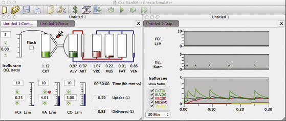
FIGURE 26-13 Gas Man (Med Man Simulations, Boston, MA) simulation of the classic square root of time closed-circuit liquid injection technique. Liquid boluses at a 0.5 mL loading dose at time (t) = 0 followed by 0.7 mL maintenance dose injected at 1, 4, and 9 minutes. Note that the alveolar isoflurane tension remains near 1 MAC (1.1%) with injections made “by the clock.”
At the end of 30 minutes of empiric intermittent liquid injection, patient uptake is again 0.6 L of isoflurane vapor (see Fig. 26-13). To achieve this, 0.8 L of vapor was delivered to the breathing circuit as five individual 0.7 mL liquid injections following a loading dose of 0.6 mL. The discrepancy between the 0.8 L delivered and the 0.4 L uptake is anesthetic vapor that remains in the breathing circuit (CKT, 6 L) and the patient’s lungs (ALV, 2 L). This same 0.1 L anesthetic volume was neglected in the previous descriptions for the sake of clarity. Other than this, the efficiency of agent use is 100%. The slight differences in uptake in Figures 26-11, 26-12, and 26-13 are due to the slight differences in anesthetic tension maintained in VRG.
The initial (average) inspired concentration necessary to achieve 1.1% alveolar tension was approximately 2.9%, as in the previous examples. Average inspired tension was allowed to fall to 1.3% at the end of 30 minutes, as before, this time by lengthening the time between liquid injections. Inspired tension varied considerably between injections, but on the average, inspired tension was similar to that for higher flow systems.
The same principles apply to desflurane closed-circuit anesthesia. Figure 26-14 shows a Gas Man simulation of closed-circuit desflurane anesthesia with a 2.0 mL initial injection followed by 1.5 mL liquid desflurane injections at 1, 4, and 9 minutes. Figure 26-15 shows a Gas Man simulation of closed-circuit desflurane anesthesia with a 2.0 mL initial injection followed by 1.5 mL liquid desflurane injections at 1, 4, and 9 minutes. At 12 minutes, 1.0 MAC levels are achieved in alveolar gas and in the vessel-rich tissue group; the vaporizer is set to 16% desflurane, and no further liquid injections are required. The vaporizer setting needs to be reduced beginning at 30 minutes.
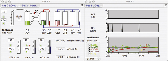
FIGURE 26-14 Gas Man simulation (Med Man Simulations, Boston, MA) of closed-circuit desflurane anesthesia with 2.0 mL initial injection followed by 1.5 mL liquid desflurane injections at 1, 4, and 9 minutes.
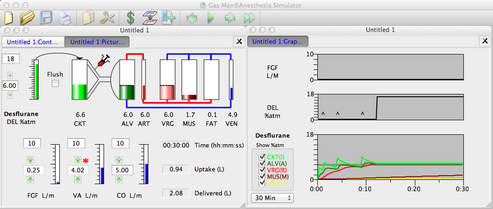
FIGURE 26-15 Gas Man (Med Man Simulations, Boston, MA) simulation of closed-circuit desflurane anesthesia with a 2.0 mL initial injection followed by 1.5 mL liquid desflurane injections at 1, 4, and 9 minutes. At 12 minutes, 1.0 MAC levels are achieved in the alveoli and vessel-rich group, the vaporizer is set to 16% desflurane, and no further liquid injections are required. The vaporizer setting needs to be reduced beginning at 30 minutes.
Choice of Anesthetic Agent
The choice of anesthetic agent should take into consideration the patient, surgery, and closed-circuit technique. Whenever a rebreathing circuit with carbon dioxide absorption is used, there is some expired admixture to FGF. As FGF is reduced toward that of a closed circuit, expired concentration plays a greater role and fresh-gas concentration plays a lesser role in determining inspired concentration. Inspired concentration is the flow-weighted average of fresh gas and expired gas concentrations. Low-solubility agents provide expired concentrations close to those of inspired concentrations. Thus they require relatively lower delivered (vaporizer) concentrations than agents of higher solubility. If the concentration required exceeds the maximum vaporizer setting, alternative administration techniques are required. Higher FGF can be used, and the closed-circuit technique abandoned, in favor of low, also called minimal, flow—at least until the vaporizer alone will suffice. Alternatively, a closed circuit can be achieved by injecting liquid anesthetic into the breathing circuit.
Only desflurane can consistently be used without the liquid injections required in a closed circuit. Desflurane’s low blood/gas solubility (0.42) and vanishingly low metabolism make it well suited for low-flow and closed-circuit anesthesia. When used this way, it becomes quite economical. The maximum vaporizer setting of 18% exceeds that necessary to maintain anesthesia depth.
Sevoflurane has relatively low blood/gas solubility (0.67) and is used for closed-circuit anesthesia in countries where there is no regulation barring it.26 In the United States, the Food and Drug Administration (FDA) package insert requires an FGF of 2 L/min for cases of a duration greater than 2 MAC × the number of hours (e.g., 1 MAC for 2 hours, 2 MAC for 1 hour). For less than this time × duration product, at least 1 L/min is required.
This FDA restriction is based on the increased heat produced by carbon dioxide absorption and the accompanying temperature rise in the carbon dioxide absorbent. Baralyme was removed from the U.S. market because of its substantial heat production.27 In many countries, a variety of “cool” CO2 absorbents are available that use lower or absent NaOH and KOH in combination with CaCO3 or other absorbents.27
The resulting increased temperature increases the degradation of sevoflurane to compound A, which is toxic in swine.27 Sevoflurane’s use in low-flow and closed-circuit situations has not shown any clinical problems.26 The maximum vaporizer setting of 8% is just sufficient to maintain anesthesia after adequate depth is attained.
Isoflurane’s higher blood/gas solubility (1.3) requires high vaporizer settings during maintenance. Indeed, the maximum isoflurane vaporizer setting of 5% is insufficient to maintain 1 MAC anesthesia in a closed circuit for the first hour.
Both isoflurane and desflurane are broken down into compounds, including carbon monoxide, when exposed to high temperatures.27 With the removal of Baralyme from the market, this is no longer a problem.28
Halothane’s high blood/gas solubility (2.4) requires particularly high vaporizer settings during maintenance. The maximum halothane vaporizer setting of 5% is insufficient to maintain 1 MAC anesthesia in closed circuit for the first hour.
The ratio of delivered to alveolar tension for several agents was first explored by Zuntz.9 Figure 26-16 shows the delivered/alveolar ratio over time simulated with Gas Man. Note that the higher the blood/gas solubility, the higher the delivered/alveolar tension ratio.
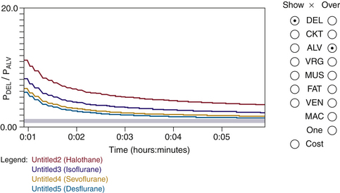
FIGURE 26-16 Delivered/alveolar tension ratio. The ratio for several agents with fresh gas flow of 6 L/min are simulated using the Gas Man (Med Man Simulations, Chestnut Hill, MA) overlay. The higher the blood/gas solubility, the higher the delivered/alveolar tension ratio. Time interval shown is 1 minute to 6 minutes.
Practical Aspects of Administration
The practical aspects of administration of closed-circuit anesthesia must be known and understood for this technique to be used effectively. Many contemporary anesthesia machines available in the United States are not designed to facilitate or allow closed-circuit techniques and thus need modification before or during use; all GE Healthcare anesthesia machines fall into this category. In the United States, the Dräger Apollo and Fabius can provide fully closed-circuit anesthesia because there is no lower limit to FGF, and return of sampled gas is facilitated by a built-in sampled gas-return port.
In some countries, GE Healthcare and Dräger both provide low-flow anesthesia machines with end-tidal control of agent and end-tidal (GE Aisys) or inspired (Dräger Zeus) control of oxygen. Neither of these provides fully closed-circuit anesthesia.
Likewise, the anesthetic record must be adapted for the closed-circuit technique. It is important for the anesthetic record to capture FGFs and vaporizer settings as well as measured inspired and end-expired concentrations. When low-flow or closed-circuit anesthesia is administered, certain additional variables need to be recorded on the anesthetic record. First, the flows of nitrous oxide, air, and oxygen must be recorded to explain what is really administered to the breathing circuit separate and distinct from the resulting inspired concentrations of oxygen, nitrous oxide, and balance gas, which is predominantly unmeasured nitrogen. Expired tidal volume should be carefully observed and recorded.
With older anesthesia delivery systems, patient ventilation was dependent on both ventilator volume settings and concurrent FGF. Newer anesthesia machines have eliminated this interaction. The vaporizer setting should be recorded, however, because the adjustment is made by the anesthesia care provider, and it influences inspired concentration. Because inspired anesthetic tension is quite different from that delivered from the vaporizer, inspired tension should be measured and recorded to demonstrate that it was known and well controlled. Finally, expired anesthetic tension should be controlled and recorded to assist in patient management. The need to monitor and record expired-agent tension applies irrespective of FGF; it is equally applicable to high-flow techniques. When all three of these variables—vaporizer setting, inspired tension, and expired tension—are recorded, the anesthetic record documents the patient’s receipt of a safe and effective anesthetic. All closed-circuit concentrations and flows should be recorded without reservation. Closed-circuit anesthesia has been shown to be as safe as a high-flow technique.29
Practical administration of closed-circuit anesthesia follows the basic principle of the technique: deliver gases and vapors at a rate equal to tissue uptake while maintaining alveolar tension at the desired level (Figure 26-11). For most adult patients, the following regimens work as a first approximation. As with any clinical technique, changes are made to adapt delivery to each patient, surgery, and anesthetic agent.
Isoflurane
Inhalation anesthesia with isoflurane is induced with high flows and is maintained for approximately 20 minutes. During this time, alveolar anesthetic tension is established at the desired level; mechanical ventilation is usually used. Before flows are reduced, exhaled tidal volume, inspired and expired agent tensions, and inspired oxygen concentration are carefully measured and recorded on the anesthetic record. Breathing circuit gas is then transferred from the ventilator to the reservoir bag by switching between the two reservoirs during mechanical or manual ventilation. This is described below. In this way, if a switch between these two is necessary later in the anesthetic, the same concentrations are breathed from either ventilation source. Flows are then reduced as described below.
Inhalation anesthesia with isoflurane can be induced with a closed-circuit technique from the outset, but a liquid circuit injection is required. I prefer avoiding nitrous oxide and making sequential 0.5 mL isoflurane injections into the inspired limb of the breathing circuit while observing inspired and expired tension on a breath-by-breath basis. Liquid anesthetic is injected whenever inspired or expired tension falls below the desired level. The location of the liquid injection is described below.
Desflurane
Desflurane can be conveniently used with closed-circuit anesthesia. Inhalation induction is avoided for clinical reasons, and desflurane is introduced after the airway is secured with a tracheal tube or supraglottic airway.
Desflurane anesthesia is easily begun with an FGF of about 1 L/min. I prefer oxygen-enriched air and the avoidance of nitrous oxide. When air is predominantly used, an FGF of 1 L/min air is supplemented to oxygen flow slightly in excess of estimated oxygen consumption. This oxygen flow is 200 mL/min in adults. Thus FGF is 1.25 L/min. With this flow rate, a vaporizer setting of 18% desflurane causes inspired and expired desflurane concentrations to rise slowly and smoothly. After about 8 minutes, the inspired concentration reaches 8%, and the expired concentration reaches 6%. At this time the vaporizer setting or FGF can be reduced. At 1.2 L/min FGF, the vaporizer setting can be reduced to 9% to 10%.
With oxygen administration during initiation of desflurane anesthesia, it is convenient to reduce the vaporizer setting to maintain inspired and expired concentrations as desired. With this technique, oxygen concentration falls to about 85% with inspired gas containing residual nitrogen, which emerges from tissues during anesthesia.
With oxygen-enriched air administration during initiation of desflurane anesthesia, inspired and expired desflurane concentrations are established before inspired oxygen is controlled to fall to the desired level, typically below 30%. I prefer to reduce inspired oxygen to the FiO2, where arterial oxygen saturation falls to 98%, rather than 100%, to be sensitive to lung shunt and be ready to reduce it. To make this safe, the pulse oximeter oxygen saturation (SpO2) audible alarm is set to 95%. SpO2 becomes a sensitive indicator of lung shunt of any source. This transforms SpO2 from a statistical safety monitor into a clinical monitor that is useful to detect many problems at an early stage. Inspired oxygen concentration is typically between 21% and 35%, depending on lung shunt and other physiology. Past authors have suggested higher inspired oxygen concentrations. The danger of administering 1 L/min air without supplemental oxygen is described under “Avoiding Hypoxia” below.
Flow Control
When a high-flow technique is used first, FGF is reduced to provide a completely closed circuit. The adjustable pressure-limiting (APL), or pop-off, valve is closed to keep gas from leaving the circuit, should the reservoir bag be used later. On older anesthesia machines, in which tidal volume and FGF were related, set tidal volume was increased to provide an undiminished exhaled tidal volume. With newer anesthesia machines that directly control inspired tidal volume, this adjustment is no longer necessary.
With agent plus nitrous oxide plus oxygen anesthesia in adults, oxygen flow is reduced to 200 mL/min, and nitrous oxide is reduced to 100 mL/min. This approximates patient uptake for these gases. With isoflurane, the vaporizer is set to 3% to provide the approximately 9 mL/min isoflurane vapor required for 0.5 MAC contribution of isoflurane. With desflurane, the vaporizer setting is 5% to provide the approximately 16 mL/min desflurane vapor required for the 0.5 MAC contribution of desflurane.
With agent plus air plus oxygen anesthesia, oxygen flow is reduced to 200 mL/min to approximate oxygen uptake, and air is turned off because there is no nitrogen uptake or elimination when circuit gas concentrations are near that of air. With isoflurane, the vaporizer is set to 5%, which does not quite supply the 18 mL/min required to maintain 1 MAC anesthesia. Either FGF must be increased periodically or liquid isoflurane must be injected occasionally. With desflurane, the vaporizer is set to approximately 14% to supply the 32 mL/min desflurane vapor required to maintain 1 MAC anesthesia.
The ventilator is adjusted so that no gas leaves the breathing circuit at the end of exhalation; the exact technique depends on the ventilator used and is described below. Typically, the ascending (standing) bellows is adjusted to prevent it from rising to the mechanical stop that initiates discharge of excess gas. A mark can be placed on the bellows housing to signify the correct end-expired bellows position. This represents a volume mark. Deviation of the bellows from this volume mark signifies inequality between total volume delivered to the circuit and volume taken up by the patient. This deviation suggests that total FGF should be modified in some way.
Changes in concentrations of gases and vapors disclose what should be changed, the direction of change, and the magnitude of change. A change in measured FIO2 suggests that a change should be made in the flow ratio of oxygen to the other gas (nitrous oxide or air). A change in inspired agent tension suggests that a change should be made in the administration of anesthetic agent. This agent administration may have been in the form or vapor or liquid. If administration is in the form of vapor from a vaporizer, the vaporizer setting should be changed. If administration is in the form of periodic liquid injection, this suggests a change in interval of the same unit dose, adjustment of the unit dose using the same interval, or some combination of change of dose and interval. If administration is in the form of a continuous liquid injection into the breathing circuit, the rate of injection is altered.
The quantification of these adjustments is not immediately obvious. When the volume of the ventilator bellows changes, flows of nitrous oxide and oxygen are adjusted in proportion to their concentrations in the breathing circuit, not according to their proportion in fresh gas. For example, if the respiratory gas monitor indicates an inspired concentration of 66% nitrous oxide and 33% oxygen, it is in this ratio that additional gas must be added to maintain the same inspired oxygen concentration. Therefore the adjustments in oxygen flow are accompanied by adjustments in nitrous oxide that in this case happen to be twice as large. That is, when oxygen flow is increased by 100 mL/min, nitrous oxide flow is increased by 200 mL/min.
When a decrease in FiO2 is noted in the absence of a change in circuit volume, oxygen flow is increased, and nitrous oxide flow is decreased, this time by equal amounts to keep circuit volume constant. Simultaneous changes in FiO2 and circuit volume require mixed compensation, which is a combination of the two techniques described.
Finally, when inspired or expired agent tension requires an increase, the vaporizer setting is increased, or additional liquid is injected into the breathing circuit. To lighten anesthesia, the vaporizer is turned off, or a liquid injection dose is withheld or delayed. An activated charcoal filter may be used to adsorb volatile agent.30-35 Charcoal functions best when a pair of filters are placed in the inspiratory and expiratory limbs of the circuit.35 Anesthesia may also be lightened by flushing the breathing circuit briefly with oxygen. When a nitrous oxide plus oxygen plus agent anesthetic is used, the agent dilution should be done with a mixture of oxygen and nitrous oxide, with flows proportional to their circuit concentrations. When an agent plus air plus oxygen anesthetic is administered, air plus oxygen is the appropriate gas for agent dilution; the latter two cannot be done simply with today’s anesthesia delivery systems. In each case the resulting change in inhaled tensions of all gases and vapors should be observed and controlled. Because lightening anesthesia happens most often near the end of anesthesia, increasing inspired oxygen concentration may be desired, and oxygen flush or increased flow can be used. This is especially true for agent plus air plus oxygen anesthesia; however, this might not be appropriate for agent plus nitrous oxide plus oxygen anesthesia.
During the administration of any anesthetic, switching between mechanical and manual ventilation (i.e., controlled and spontaneous, respectively) is often desired. This change influences closed-circuit anesthesia in several ways. First, if the content of the reservoir bag and bellows is different, switching modes will produce a change in gas composition. This usually is not desired. Such a change is averted by emptying whichever gas reservoir is not in use, bellows or reservoir bag, and transferring circuit gases back into the empty reservoir (bellows or bag) when convenient. This is done in a manner that will be described below.
When a change in the volume in the ventilator bellows or reservoir bag is desired, this can be accomplished by switching between bag and ventilator. To do this, the clinician maintains a partially filled reservoir bag throughout the case. Meanwhile, the patient is ventilated mechanically. Whenever it becomes necessary to compensate for accumulated circuit volume change, gas is transferred between bellows and bag. This is done by transferring gas via the patient’s lungs during exhalation. Deft adjustment of the bag/bellows selector lever is required. The same technique is used to fill the out-of-use reservoir bag or ventilator bellows, as introduced above.
With the earlier Ohmeda (GE Healthcare) breathing circuit assembly (Modulus 2 Plus), when the selector valve was moved 5% of the way from “Vent” to “Bag,” the ventilator and bag were connected to each other, and gas could be easily transferred without using the patient’s lungs as a temporary reservoir. With newer anesthesia delivery systems, this is no longer possible. With the GE Aestiva, using the patient’s lungs can successfully act as a transfer volume. This is because the switch to ventilator mode interposes a momentary expiratory pause, during which the patient’s lungs can empty into the ventilator bellows. When transferring gas from the bellows to the reservoir bag, switching the mode from “Vent” to “Bag” at the beginning of exhalation fills the reservoir bag and leaves the ventilator bellows partly empty.
With the GE Advanced Breathing System (ABS) Aespire, Avance, and Aisys workstations, switching to mechanical ventilation mode begins instantly with the inspiratory phase of ventilation. Thus the patient’s first tidal volume may be increased above the set tidal volume under some conditions.
With the Dräger FGF decoupling machines (e.g., Fabius, Apollo, and in some countries, Julian), the reservoir bag is in the expiratory limb of the breathing circuit during mechanical and manual/spontaneous ventilation. Therefore the bag contains gases and vapors of the correct concentration and sufficient volume to switch ventilation modes at any time. In these Dräger anesthesia delivery systems, the clinician must be aware that switching from vent to bag creates a moment in which the reservoir bag positive-pressure relief valve is open. Squeezing the reservoir bag during this period results in lost volume from the circuit to the scavenger interface. With high-flow anesthesia, this is not a problem; but with low-flow or closed-circuit anesthesia, this will leave the reservoir bag empty, and it will not refill. Thus the user must delay squeezing the reservoir bag until the valve closes (about 1 second).
Respiratory Gas Sampling
Respiratory gas sampling for analysis complicates low-flow and closed-circuit administration unless pure sampled gas is returned to the breathing circuit. This can be done simply and conveniently by connecting the sampled gas return tube to the expiratory limb or to the carbon dioxide absorber itself using a reusable or disposable adapter. This connection exists as an FDA-approved feature in newer Dräger anesthesia delivery systems (e.g., Tiro, Fabius GS, and Apollo). This connection does not exist in GE anesthesia delivery systems. This connection is already made in the Dräger Apollo.
Although a truly closed circuit cannot be achieved without gas return, circuit loss to sampling can be compensated by the addition of fresh gas to offset the loss. An excessive gas sampling rate can produce negative pressure in the breathing circuit and can deplete the volume necessary for patient ventilation.36,37 To compensate for gas sampling without sample gas return, the anesthesiologist increases nitrous oxide, oxygen, and agent flows by an amount equal to the respective rate of removal by the gas sampling system. This total sampling flow varies slightly among manufacturers and models, but it is usually between 200 and 300 mL/min total flow.
Correcting for sample gas loss requires certain considerations. Sample gas composition equals circuit composition, which is a mixture of inspired and expired gas, weighted according to the inspiratory and expiratory times. Throughout most of the duration of the anesthesia, inspired and expired values do not differ by an amount that affects this minor correction. Because all of the exhaled gas is rebreathed (with carbon dioxide removed), circuit composition is dominated by the composition of exhaled gas with slight alteration by fresh gas.
When breathing circuit composition is 66% nitrous oxide, 33% oxygen, and 0.5% isoflurane, gas sampled from the breathing circuit will approximate this composition. Thus if the sampling rate is 250 mL/min, an additional 165 mL/min (250 × 0.66) nitrous oxide, 82 mL/min oxygen, and 2 mL/min isoflurane must be added to compensate for the loss of sampled gas. The total resulting flows and concentrations are 265 mL/min nitrous oxide, 282 mL/min oxygen, and 18 mL/min isoflurane, or 3% of FGF. Rounding off for convenience, with nonreturn airway gas sampling, FGF is adjusted to 300 mL/min oxygen and 300 mL/min nitrous oxide, and the vaporizer is set to 3% (halothane or isoflurane) as a reasonable starting point.
When the breathing circuit composition is desflurane 6% in oxygen, oxygen flow is increased by 300 mL/min to a total of 500 mL/min. When the breathing circuit composition is desflurane 6% in 25% oxygen, to a first approximation, the sample gas is compensated with pure air. This is then corrected with a decrease of 50 mL/min air and an increase of 50 mL/min oxygen. Most anesthesia machines do not have the precision to do this well.
Whenever nitrous oxide is administered to a closed circuit, concentration or tension of oxygen in the breathing circuit must be monitored even more carefully than usual. This is because in a closed circuit, inspired oxygen concentration depends on both gas delivered from the anesthesia machine (FGF) and that exhaled by the patient. Inspired oxygen tension or concentration must be monitored to ensure the safety of gases inspired by the patient. When low flows are used, oxygen concentration alarms should be set tightly above and below the desired FiO2. Expired as well as inspired oxygen concentration monitoring is advisable when possible, and arterial oxygen saturation should always be monitored, as for any other anesthetic; this is discussed further in the section “Avoiding Hypoxia.” When air is added to a closed circuit, usually because of sample gas discard, FiO2 must be monitored and alarmed very carefully.
In contrast to high-flow systems, in which FGF to the circuit replaces carbon dioxide–laden exhaled gas, closed-circuit anesthesia requires effective carbon dioxide absorption. Thus, carbon dioxide monitoring (capnography) is even more important with low flows than with high flows. A functioning carbon dioxide absorber must always be ensured, which is accomplished by monitoring inspired partial pressure of carbon dioxide (PiCO2). A carbon dioxide level of more than 5 mm Hg is cause for concern. When this is seen, I advise an increase in FGF to twice the minute ventilation, ensuring that PiCO2 falls to approximately zero. If it does, the carbon dioxide absorbent should be presumed to be used up and no longer effective. Carbon dioxide absorbent should be replaced at this time; if this is accomplished by an exchange of carbon dioxide absorber assembly, the original absorbent should be retained briefly. If the new carbon dioxide absorbent exhibits the same PiCO2 greater than 5 mm Hg, the carbon dioxide absorbent is not the problem. Rather, the problem is usually an inappropriate estimation of inspired concentration by the gas monitor; in rare cases, it might represent a breathing circuit valve malfunction. If the carbon dioxide absorbent is changed, recognize that the volatile agent absorbed in the absorbent granules and stored in the absorbent empty spaces must be replaced by additional anesthetic agent. Careful addition of vapor or liquid should be performed while observing inspired agent tension and bringing it to what it was before the absorbent change. Do not rely on expired agent tension, because its change will be slow and will lead to not fully replacing the lost agent.
Liquid Agent Injection
Where to inject liquid agent is an interesting question. Early writings advocated injecting into the expiratory limb of the circuit to avoid unmonitored and unknown changes in inspired tension. Careful monitoring of airway anesthetic tension allows liquid injection closed-circuit anesthesia to be performed simply and safely. Figure 26-17 shows the time course of airway anesthetic tension in response to a 1.0 mL injection of liquid isoflurane into the expiratory limb of the breathing circuit connected to a 70-kg patient undergoing surgery. With this agent monitor, concentration rises with each inspiration and falls with each expiration. Thus the peaks and troughs represent inspired and end-tidal anesthetic tensions, respectively. Separate curves connecting all the peaks and all the troughs would follow the “I” and “E” curves of the isoflurane simulations in Figs. 26-12 and 26-13. Note that inspired tension does not rise for 1 minute, and an additional 1.5 minutes elapses before peak inspired tension is reached. At the peak, inspired tension rises by 1.5% from its baseline of 0.5%. Meanwhile, expired tension rises by 0.7% from 0.5% to 1.2%.
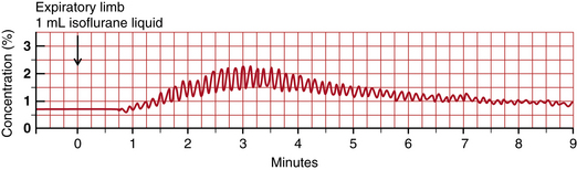
FIGURE 26-17 Expiratory limb injection. Time course of airway anesthetic tension after injection of 1.0 mL liquid isoflurane into the expiratory limb of the breathing circuit. Peaks are inspired tension and troughs are expired tension. Inspired tension begins to rise 1 minute after injection. Inspired and expired tensions begin to rise 2.5 minutes after injection and reach peak values 3 minutes after injection.
With the advent of breath-by-breath monitors of anesthetic agents, it became obvious that injection in the inspiratory limb is possible and advantageous. Figure 26-18 shows the result of a 1.0 mL liquid isoflurane injection into the inspiratory limb of the circuit in the same patient. Inspired tension peaks at 4.4% above baseline after two breaths (15 seconds). Expired tension rises by 1.2% within two breaths and remains constant for about 2 minutes, and 3 minutes after injection, the two tracings that depict injection in the two circuit locations become quite similar. A note of caution is in order here: when injected into either the inspired or the expired limb, liquid anesthetic must never be allowed to reach the patient. Conventional breathing circuits with a dependent section between the carbon dioxide absorber and the patient easily achieve this. Continuous, breath-by-breath gas monitoring helps the clinician ensure that inspired and expired tensions are as desired and expected. Figure 26-19 shows alternate injections of 0.5 mL of liquid isoflurane into the inspiratory and expiratory limbs of the circuit. In each case, injection into the inspiratory limb resulted in an inspired peak within two breaths, whereas injection into the expiratory limb resulted in an inspired peak approximately 90 seconds after injection. Injection into the inspiratory limb provides superior control of inspired and expired anesthetic tension. An exhaled limb injection may be acceptable when constant depth is the goal. Figure 26-20 shows a 6 minute trend graph of inspired and expired desflurane concentration after 1 mL desflurane liquid injections were made into the inspired circuit limb adjacent to the carbon dioxide absorber. Note that inspired tension rises to 3% quickly. This small rise in inspired tension does not generally elicit a sympathetic response.
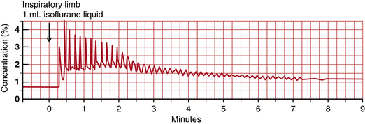
FIGURE 26-18 Inspiratory limb injection. Time course of airway anesthetic tension after injection of 1.0 mL liquid isoflurane into the inspiratory limb of the breathing circuit. Peaks are inspired tension and troughs are expired tension. Inspired tension rises to 4.5% two breaths after injection. Expired tension peaks after two breaths at 1.7% after two breaths (1.2% above its value two breaths earlier) and remains at this level for several minutes.
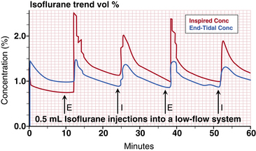
FIGURE 26-19 Alternate injections into the inspiratory (I) and expiratory (E) circuit limbs. In each case, inspiratory limb injection resulted in an inspired peak within two breaths, and expiratory limb injection resulted in end-tidal peak approximately 90 seconds after injection. The red tracing represents inspiratory isoflurane tension, and the blue tracing represents tidal expiratory isoflurane tension.
FIGURE 26-20 Solar 8000i physiologic monitor (GE Healthcare, Waukesha, WI). Display of a 6-minute graph of inspired and expired desflurane (top left), oxygen (middle left), and carbon dioxide (bottom left). Injections of 1 mL desflurane are made in the inspired limb of the breathing circuit.
Many anesthesiologists use a concentration-calibrated vaporizer for closed-circuit anesthesia. Some adjust the vaporizer by intermittently selecting between full on and full off. With low flow through a concentration-calibrated vaporizer, the time constant (τ) for circuit tension change is long, because τ is equal to circuit volume divided by circuit flow in a fully mixed circuit. With a volume of 8 L (6 L circuit + 2 L lung volume or functional residual capacity [FRC]) and a flow of 0.25 to 0.5 L/min, τ is between 32 and 16 minutes. Because of this, even a drastic change in vaporizer setting produces a very slow change in the composition of inspired gas. If faster control is desired, either FGF must be increased or liquid must be injected.
Closed-circuit anesthesia can also be administered via measured-flow vaporizers (e.g., Copper Kettle and Vernitrol). However, because of the potential for error in the calculations required,38 and the fact that these vaporizers are considered obsolete, their use is discouraged (see also Chapter 3).38
The initial administration of inhaled agents can be performed by liquid injection. With desflurane, a convenient liquid volume for adults is 1.0 mL. Figure 26-20 is a screen shot of the 6-minute graph of inspired and expired desflurane concentration. When the same administration sequence is viewed over a 15-minute window, the bumps in inspired and expired concentration are smoothed, and the inspired and expired curves appear just as they would with careful vaporizer use with high or low FGF.
lack of Buildup of Toxic Substances
When high flows are used during anesthesia, gases in the breathing circuit are replaced frequently. Thus any gases that might accumulate in the breathing circuit are removed and replaced with fresh gas. In a closed circuit, all substances entering the breathing circuit remain there unless taken up by the patient, carbon dioxide absorbent, or circuit materials.
Circuit contaminants can arise from several sources.39 Anesthetics by themselves or in reaction with soda lime can produce unintended substances. Specifically, halothane produces two metabolites, 2-chloro-1,1,1-trifluoroethane (CF3CH2Cl) and 2-chloro-1,1-difluoroethylene (CF2CHCl), and they produce a metabolite decomposition product, 2-bromo-2-chloro-1,1-difluoroethylene (CF2CBrCl). Concentrations in a closed circuit are no higher than in a semiclosed circuit, and the decomposition product is not present in an absorbent-free Bain circuit, although these substances are not believed to be a hazard.40,41
Enflurane,42 isoflurane,43 and desflurane44 are stable enough to warrant no special concern during closed-circuit anesthesia. Sevoflurane45 has been shown to produce three breakdown products in soda lime. The first is compound A, or fluoromethyl 2,2-difluoro-1-(trifluoromethyl)-vinyl ether, alternatively called 1,1,1,3,3-pentafluoroisopropenyl fluoromethyl ether, or PIFE (F2C=C[CF3]OCH2F). The second is compound B, or fluoromethyl 2-methoxy-2,2 difluoro-1-(trifluoromethyl)-ethyl ether, alternatively called 1,1, 1,3,3-pentafluoro-3-methoxy-isopropyl fluoromethyl ether, or PMFE (H3COCF2CH[CF3]OCH2F). The third is hexafluoroisopropanol, or HFIP. In a closed circuit, PIFE and HFIP concentrations remain low; the safety of PMFE in a closed-circuit system is still under investigation.
Patients can produce substances that would be better removed from the breathing circuit than rebreathed. One such product is carbon monoxide.46 In addition, tissue nitrogen continues to be released into the breathing circuit47 at a rate of approximately 10 mL/min and accounts for a slow asymptotic rise in circuit nitrogen toward 10% without exceeding this value.48 Acetone, methane, and other inert gases also build up.49 However, values attained are less than those allowed for chronic occupational exposure.50 It is possible that the breathing circuit should be flushed periodically with a high FGF, although the need for this has not been established.
During laparoscopy or other surgeries in which carbon dioxide is used to distend a body space (insufflation), carbon dioxide is absorbed. This absorption is not accompanied by increased oxygen consumption; therefore FGF does not need to be increased. When oxygen consumption changes for any reason, this will be detectable by changes in circuit volume and gas composition. Thus in situations such as shock or decreased oxygen consumption in shock, changes in oxygen consumption may be observed. The information obtained from closed-circuit anesthesia provides insight into changing physiology.
Substances can also enter the breathing circuit from other sources. For example, acrylic monomer is exhaled when joint prostheses are surgically cemented. During this period, the closed circuit should be interrupted, and high FGF should be used to prevent rebreathing of this chemical.
Some gas monitors sample room air or calibration gases intermittently. The Ohmeda Rascal and Rascal II (GE Healthcare) self-zero with argon and room air periodically. Argon buildup is insignificant, as is nitrogen accumulation.48 The electronic paramagnetic oxygen monitors used in some multigas monitors entrain room air for continuous calibration. If the instrument combines calibration gas with sampled patient gas, gas returned from the instrument contains room air, and nitrogen accumulation in the closed circuit is noticeable and significant. This problem makes the GE Healthcare gas monitors problematic for closed-circuit anesthesia administration.51
Avoiding Hypoxia
During anesthesia, hypoxia must be avoided, so its likelihood must be reduced to as close to zero as possible. It is crucial to understand how inspired hypoxia can develop during closed-circuit and even low-flow anesthesia.
In a closed circuit, as long as oxygen administration exceeds oxygen uptake, inspired oxygen concentration rises. In steady state, oxygen administration exactly equals oxygen uptake, and FiO2 remains constant. This is a fundamental principle of closed-circuit anesthesia.
In low-flow non–closed-circuit situations, oxygen delivery in excess of uptake is not sufficient to avoid falling FiO2 and inspired hypoxia. This is because in all non–closed-circuit situations, gas leaves the breathing circuit, and this gas includes oxygen. Thus a 1 L/min FGF of air inevitably leads to inspired hypoxia in a 70-kg patient. This is because a 70-kg awake patient consumes about 250 mL/min oxygen, and this value falls to about 210 mL/min under anesthesia. With an FGF of 1 L/min of air, 790 mL/min nitrogen and 210 mL/min oxygen are delivered to the breathing circuit. Thus oxygen delivery exactly equals oxygen uptake. But each minute, uptake of oxygen is 210 mL, and uptake of nitrogen is zero. Thus the net flow to the breathing circuit is 790 mL/min nitrogen and 0 mL/min oxygen. Breathing circuit oxygen concentration therefore falls, and it falls linearly, because oxygen is taken up at a constant rate until life ceases or is diminished. Thus in a breathing circuit and patient lungs with a combined volume of 8 L, FiO2 will fall 2.6%/min ([0.21 L/min]/8 L = 0.026/min). Figure 26-21 shows the graph of FiO2 and SpO2 over time in an 84 kg subject breathing FGF at 1 L/min air plus 0.050 L/min oxygen from a semiclosed breathing circuit (Ohmeda Modulus 2+ CD anesthesia machine with a GMS absorber assembly). After 12 minutes, FiO2 fell to 8% and SpO2 fell to 82% when the demonstration was terminated.
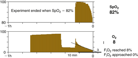
FIGURE 26-21 Graph of the fraction of inspired oxygen (FiO2) and pulse oximeter value (SpO2) over time. An 84-kg patient breathing fresh gas flow at 1 L/min air plus 0.050 L/min oxygen from a semiclosed breathing circuit (Ohmeda Modulus 2 Plus or Modulus CD anesthesia machine with GMS absorber assembly; GE Healthcare, Waukesha, WI). After 12 minutes, FiO2 fell to 8%, SpO2 fell to 82%, and the demonstration was terminated. The patient had no ill effects. The early exponential fall describes a first order, proportional uptake, process. The later linear fall implies zero order, constant uptake, process.
Machine Requirements
For an anesthesia machine to facilitate administration of closed-circuit anesthesia, several specifications should be met (Box 26-1).
Using Today’s Technology: Practicalities
As of 2012, anesthesia machines generally did not meet all the requirements for closed-circuit anesthesia; some needs were met, but some were not. The two largest manufacturers that supply the U.S. market and the rest of the world have introduced anesthesia machines that provide control of end-tidal anesthetic agent concentration and control of inspired (Dräger) or end-expired (GE Healthcare) oxygen concentration. To maintain constant levels of these variables, such machines use low to very low FGFs but not a closed circuit. To change these variables, they use an FGF higher than what most anesthesiologists practicing closed-circuit anesthesia with an older machine would use.
GE Healthcare anesthesia delivery systems have a particular limitation. Their gas monitoring module draws a reference flow of room air to the oxygen sensor at a rate of 27 to 45 mL/min. This additional air exits with the sampled gas. In the United States, where end-tidal control is not available, sample gas return is not FDA approved; however, in others countries, it is. Clinicians performing manual closed-circuit anesthesia have always returned sampled gas to the breathing circuit to quantify the true closed-circuit flows. With GE Healthcare gas monitors, when sampled gas is returned to the circuit, its room-air content lowers circuit concentration of oxygen, agent, and nitrous oxide while increasing circuit volume and making the bellows rise. This breaks the simplicity and accuracy of closed-circuit anesthesia whenever monitors such as this are used, no matter what anesthesia delivery system is used.
An additional limitation of the Aisys machine is that it does not allow FGF less than 200 mL/min and only allows FGF to be changed 50 mL/min at a time. When one of the goals of closed circuit-anesthesia is to quantify oxygen and agent delivery, this precision is not sufficient. The letter “X” in the module number designates that the gas monitoring module computes oxygen uptake and carbon dioxide exhalation. This is computed using the on-airway gas monitoring connection.
With Aisys it is difficult to provide manual breaths intermixed with ventilator breaths in that the reservoir bag contains an older concentration than does the ventilator bellows. Mechanical techniques of transferring gas between bag and bellows by giving a breath to the patient from one source and causing the patient to breathe to the other is difficult because of the immediate inspiratory ventilator phase when the “Bag/Mechanical” switch is set to mechanical ventilation.
Dräger Apollo, the highest technology Dräger machine available in the United States, allows closed-circuit anesthesia to be performed. That is, flows can be reduced to near zero, there is no electronic limitation of resolution; the vaporizer functions properly over the whole range of flows; and there is no room air contamination of the sampled gas, which is returned to the circuit whether low FGF is used or not. Also, the reservoir bag is in the circuit during both mechanical and manual ventilation; thus ventilation can be switched from bag to ventilator at any time and not change breathing circuit concentration of any gas. A fresh gas wizard encourages FGF as low as 0.5 L/min but gives a warning with lower FGF, even when it is within reasonable closed-circuit ranges, well above the patient’s metabolic and distributive needs.
Dräger Fabius and Tiro series machines have all the Apollo features except the low-flow wizard. They do not come with an integral gas monitor, so the closed-circuit practitioner should choose one that does not entrain room air into the sample gas return. Dräger Zeus is approved and available in many countries, including Canada. It uses very different technology than other anesthesia machines and uses low but not closed-circuit flows.
Most other anesthesia machines on the world market will allow conventional closed-circuit anesthesia. With some, the user must implement sample gas return with an appropriate connector. New standards for small connectors are in the process of change.
To provide liquid injection, adapters are typically purchased specially or are fabricated by the user. Many configurations are used,52 but none is ideal. Figure 26-22 shows an example of a system I use for inspiratory liquid injection and expiratory sample gas return. Here it is implemented on a Dräger Fabius GS anesthesia machine. The plastics shown are all compatible with both sevoflurane and desflurane. The Cardinal Health (Miamisburg, OH) bronchodilator inhaler product has a Silastic cover over a tiny hole, which allows liquid anesthetic injection through the silastic cover via a needle. In addition to plastic/anesthetic compatibility concerns, components for liquid injection must be selected to reduce the likelihood of unintentional overdose from unintended excess liquid agent being injected into the circuit. The plastic syringe shown provides the static friction that glass lacks. The 23-gauge standard needle (shown) or a 22-gauge spinal needle provides resistance to liquid flow, and the bend in the needle inverts the syringe to offset the effect of gravity on the plunger.
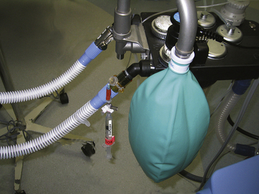
FIGURE 26-22 Liquid anesthetic agent injection system that can be used in a closed-circuit system. Note that the syringe barrel is up. This averts the possibility that vaporized anesthetic forces liquid anesthetic into the breathing circuit, which presents a hazard with desflurane.
Whenever desflurane liquid is placed in a syringe, the syringe should never be directed downward. When the syringe is directed downward, any liquid formed from vaporization will push liquid desflurane out of the bottom of the syringe and into the breathing circuit. Desflurane has a vapor/liquid volume ratio of 209. Therefore, if 1 mL of vapor is formed at the top of the syringe, it will force 1 mL of liquid desflurane out of the bottom of the syringe; this liquid volume will form 209 mL of desflurane vapor. When the desflurane syringe is directed upward, when 1 mL of vapor is formed, only that 1 mL of vapor leaves the syringe and enters the breathing circuit. To attach the syringe to the breathing circuit, it is useful to bend the needle that links the syringe to the breathing circuit adapter. This holds it in place while pointing the syringe upward. The presence of a bent needle, a clear caution label, and the statement of the drug name combine to increase the safety of this technique. If a syringe pump is to be used for liquid infusion into the breathing circuit, a bent 22-gauge spinal needle allows reasonable freedom of motion for the pump. Some syringe pump infusion tubing sets are not compatible with any inhaled anesthetic liquid, so special caution must be exercised when using them. One example is the tubing for the Infuse-OR syringe pump (Baxter, Deerfield, IL), which is well suited for agent injection by bolus plus infusion.
Idiosyncrasies of Contemporary Anesthesia Machines
Some contemporary anesthesia machines make the administration of closed-circuit anesthesia difficult. The aging Dräger Narkomed series presents several unique impediments. FGF below 300 mL/min is difficult to produce, and nitrous oxide cannot be administered without sounding an alarm when oxygen flow is below 1 L/min. The bag/ventilator selector valve has a water-venting hole that must be occluded to prevent a slow loss of reservoir-bag gas to the room during mechanical ventilation. On this machine, end-expiratory bellows height determines delivered tidal volume. Specifically, inspiration is accomplished by bellows descent from its starting volume downward to zero volume. Thus as circuit volume changes, end-expiratory bellows height changes, and tidal volume changes follow.
The aging Ohmeda Modulus II (GE Healthcare) machine facilitates closed-circuit administration in several ways. An optional factory or field modification provides calibrated oxygen flow as low as 50 mL/min. Calibration resolution is no better than 50 mL/min, however. Up to 75% nitrous oxide can be delivered at any oxygen flow, and concentrations above this are prevented by a chain linking the oxygen and nitrous oxide flow-control needle valves (see Chapter 2). The 75% limitation still precludes closed-circuit nitrous oxide induction, which requires 2 L/min nitrous oxide for a brief period, while oxygen consumption is only 250 mL/min.
The Modulus II system has no intentional circuit leaks, and incorrect bellows position (within limits) does not affect tidal volume during mechanical ventilation. This is accomplished by a fixed volume of driving gas compressing the bellows, which delivers the actual inspired tidal volume. Inspired tidal volume diminishes only when volume in the bellows is insufficient. This causes an alarm to sound.
The separate control for ventilator setting and ventilator-in-circuit provides a unique but subtle advantage. In low-flow or closed-circuit circumstances, when the ventilation source is switched from bag to ventilator, it is important that there be sufficient gas in the ventilator bellows to provide the set tidal volume; insufficient bellows volume at the transition time is a significant problem in many anesthesia delivery systems. This transition is accomplished with the Modulus II by squeezing the reservoir bag to give a tidal volume to the patient and sliding the “Bag/Vent” lever to “Vent.” The patient’s exhaled tidal volume then fills the bellows. As soon as the bellows is sufficiently filled (~1 second) and the ventilator is turned on by the clinician, a proper tidal volume is delivered. The danger of independent controls for mechanical connection and ventilator operation made this independence dangerous, and it is not present on later machines. However, bellows filling from the patient’s exhaled gas could be accomplished if there were a 1- to 2-second delay before inspiration began when the combined switch was set to “Vent.”
Anesthesia Machines in the United States
Dräger Apollo, Fabius, and Tiro are all capable of FGF down to 100 mL/min. Apollo has sample gas returned to the breathing circuit via internal connections, so the user need not make any changes. Apollo guides the user to use flows less than 500 mL in excess of patient uptake. The Datex-Ohmeda (GE Healthcare) Aestiva allows FGF down to zero, but there is no connection for sample gas return. The Datex-Ohmeda Aespire and Avance allow FGF as low as 50 mL/min, but there is no connection for sample gas return. The Aisys has 200 mL/min minimum oxygen flow with 50 mL/min increments. Aisys air flow is zero, 100 mL/min, and higher with 50 mL/min increments. There is no connection for sample gas return, and if sample gas is returned from a GE monitor, room airflow of 10 to 40 mL/min accompanies it. This makes Aisys difficult to use for closed-circuit anesthesia. Box 26-1 shows closed-circuit attributes of anesthesia delivery systems available in the United States as of the time of this writing.
The Future
The future of closed-circuit anesthesia is uncertain. Although it has been practiced and advocated for many years, closed-circuit anesthesia is currently used only in a few centers and only by a small number of individuals in the United States. Obstacles to its practice fall into two categories: technological and philosophical.
The technological encumbrances to closed-circuit anesthesia were described earlier in this chapter. They make closed-circuit administration inconvenient. Philosophical encumbrances usually center on issues of safety. Even though this issue has been adequately addressed,29,53,54 lack of an obvious relationship between control settings and inspired gas is disconcerting to many practitioners. Monitoring of inspired and expired gas tensions and exhaled volume becomes more critical. Finally, a greater understanding of drug kinetics is required for a full understanding of the technique.
In Europe, closed-circuit anesthesia has had equipment to support it.55 The PhysioFlex56,57 anesthesia machine (Dräger Medical) was introduced in the late 1980s. It provided automated closed-circuit anesthesia. The Dräger Zeus was introduced in 2003 in Europe, and it provides near–closed-circuit anesthesia when possible while controlling end-expired anesthetic concentration and inspired oxygen concentration. The Zeus was introduced in Canada in 2011.
summary
Closed-circuit anesthesia is a technique that maintains a constant anesthetic state by adding gases and vapors to the breathing circuit at the same rate that the patient’s body redistributes (stores) or eliminates them. Some practitioners use liquid anesthetic injection at prescribed time intervals using the empiric square-root-of-time model; others monitor and maintain inspired or expired anesthetic tensions using a gas monitor that returns analyzed gas to the breathing circuit. A commercial almost–closed-circuit anesthesia machine is available in Europe.
References
1. Bengston J.P., Bengston A., Stenqvist O. The circle system as a humidifier. Br J Anaesth. 1989;63:453–457.
2. Lowe H.J. Dose regulated Penthrane (methoxyflurane) anesthesia. Chicago: Abbott Laboratories; 1972.
3. Lowe H.J., Mackrell T.N., Mostert J.W., et al. Quantitative closed circuit anesthesia. Anesthesiol Rev. 1974;12:16–19.
4. Aldrete J.A., Lowe H.J., Virtue R.W., eds. Low flow and closed system anesthesia. New York: Grune and Stratton, 1979.
5. Lowe H.J., Ernst E.A. The quantitative practice of anesthesia: use of closed circuit. Baltimore: Williams & Wilkins; 1981.
6. Severinghaus J.W. The rate of uptake of nitrous oxide in man. J Clin Invest. 1954;33:1183–1189.
7. Connor C.W., Philip J.H. The Severinghaus square root of time relationship for anesthetic uptake and its implications for the stability of compartmental pharmacokinetics, Physiol Meas. 2008;29:685–701. http://iopscience.iop.org/0967-3334/29 Available online at
8. Connor C.W., Philip J.H. Closed-form solutions for the optimum equivalence of first-order compartmental models and their implications for classical models of closed-circuit anesthesia. Physiol Meas. 2009;30:N11–N21.
9. Zuntz N. Zu Pathogenese und Therapie der durch rasche luft druck anderungen erzeliegten krankheiten. Fortschr Med. 1897;15:632.
10. Kleiber M. Body size and metabolism. Hilgardia. 1932;6:315–353.
11. Brody S. Bioenergetics and growth. New York: Reinhold; 1945.
12. Lowe H.J., Hagler K. Clinical and laboratory evaluation of an expired anesthetic gas monitor (Narko-test). Anesthesiology. 1971;34:378–382.
13. Eger E.I., II., Guadagni N.P. Halothane uptake in man at constant alveolar concentration. Anesthesiology. 1963;24:299–304.
14. Kety S.S. The physiological and physical factors governing the uptake of anesthetic gases by the body. Anesthesiology. 1950;11:517–526.
15. Kety S.S. The theory and application of the exchange of inert gas at the lungs and tissues. Pharmacol Rev. 1951;3:1–41.
16. Philip J.H. Gas Man: an example of goal-oriented computer-assisted teaching which results in learning. Int J Clin Mon. 1986;3:165–173.
17. Garfield J.M., Paskin S., Philip J.H. An evaluation of the effectiveness of a computer simulation of anesthetic uptake and distribution as a teaching tool. Med Educ. 1989;23:457–462.
18. Eger E.I., Shafer S.L. Context-sensitive decrement times for inhaled anesthetics. Anesth Analg. 2005;101:688–696.
19. Bouillon T., Shafer S. (Editorial) Hot air or full steam ahead? An empirical pharmacokinetic model of potent inhaled agents. Br J Anaesth. 2000;84:429–431.
20. Eger E.I., II. Anesthetic uptake and action. Baltimore: Williams & Wilkins; 1974.
21. Mapleson W.W. An electrical analogue for the uptake and exchange of inert gases and other agents. J Appl Physiol. 1963;18:197–204.
22. MacKrell T.N. An electrical teaching model. In: Papper E.M., Kitz R.J., eds. Uptake and distribution of anesthetic agents. New York: McGraw-Hill; 1963:215–223.
23. Leroux J.G., Booij L.H. Model-based administration of inhalation anaesthesia 1. Developing a system model. Br J Anaesth. 2001;86:12–28.
24. Gravenstein J.S. Training devices and simulators. Anesthesiology. 1988;69:295–297.
25. Eger E.I., Bahlman S.H. Is the end-tidal anesthetic partial pressure an accurate measure of the arterial anesthetic partial pressure? Anesthesiology. 1971;35:301–303.
26. Bito H., Ikeda K. Closed-circuit anesthesia with sevoflurane in humans: effects on renal and hepatic function and concentrations of breakdown products with soda lime in the circuit. Anesthesiology. 1994;80:71–76.
27. Kharasch E.D., Powers K.M., Artru A.A. Comparison of Amsorb, sodalime, and Baralyme degradation of volatile anesthetics and formation of carbon monoxide and compound A in swine in vivo. Anesthesiology. 2002;96:173–182.
28. ECRI Health Devices Alerts, October 8, 2004, Vol 28, No. 41.
29. Ernst E.A., MacKrell T.N., Pearson J.D., et al. Patient safety: a comparison of open and closed anesthesia circuits [abstract]. Anesthesiology. 1987;67(3A):A474.
30. Epstein H.G. Removal of ether vapour during anaesthesia. Lancet. 1944:114–116.
31. Hawes D.W., Ross J.A.S., White W.C., et al. Servo-control of closed circuit anaesthesia. Br J Anaesth. 1982;54:229–230.
32. Ernst E.A. Use of charcoal to rapidly decrease depth of anesthesia while maintaining a closed circuit. Anesthesiology. 1982;57:343.
33. Baumgarten R.K. Simple charcoal filter for closed circuit anesthesia. Anesthesiology. 1985;63:125. (letter)
34. Jantzen J.P. More on black and white granules in the closed circuit. Anesthesiology. 1988;69:437–438. (letter)
35. Birgenheier N., Stoker R., Westenskow D., Orr J. Activated charcoal effectively removes inhaled anesthetics from modern anesthesia machines. Anesth Analg. 2011;112:1363–1370.
36. Huffman L.M., Riddle R.T. Mass spectrometer and/or capnograph use during low-flow, closed circuit anesthesia administration [letter]. Anesthesiology. 1987;66:439–440.
37. Mushlin P.S., Mark J.B., Elliott W.R., et al. Inadvertent development of subatmospheric airway pressure during cardiopulmonary bypass. Anesthesiology. 1989;71:459–462.
38. Keenan R.L., Boynan C.P. Cardiac arrest due to anesthesia: a study of arrest incidents and causes. JAMA. 1985;253:2373.
39. Morita S. Inspired gas contamination by non-anesthetic gases during closed-circuit anesthesia. Journal of the Society for Closed Circuit Anesthesia. 1985;2:24–25.
40. Sharp J.H., Trudell J.R., Cohen E.N. Volatile metabolites and decomposition products in man. Anesthesiology. 1979;50:2.
41. Eger E.I., II. Dragons and other scientific hazards. Anesthesiology. 1979;50:1. (editorial)
42. Eger E.I., II. Enflurane: a compendium and reference, ed 3. Madison, WI: Anaquest; 1985.
43. Eger E.I., II. Isoflurane: a compendium and reference, ed 2. Madison, WI: Anaquest; 1985.
44. Eger E.I., II. Stability of I-653 in soda lime. Anesth Analg. 1987;66:983–985.
45. Hanaki C., Fujii K., Morio M., et al. Decomposition of sevoflurane by soda lime. Hiroshima J Med Sci. 1987;36:61–67.
46. Speiss W. To what degree should we be concerned about carbon monoxide accumulation in closed circuit anesthesia? Journal of the Society for Closed Circuit Anesthesia. 1984;1:8.
47. Barton F.L., Nunn J.F. Use of refractometry to determine nitrogen accumulation in closed circuits. Br J Anaesth. 1975;47:346–349.
48. Philip J.H. Nitrogen buildup in a closed circuit [abstract]. Anesthesiology. 1990;73:A465.
49. Bengston J.P., Sonander H., Stenqvist O. Denitrogenation and low flow anesthesia. Journal of the Society for Closed Circuit Anesthesia. 1988;5:8–9.
50. Morita S., Latta W., Hambro K., et al. Accumulation of methane, acetone and nitrogen in the inspired gas during closed-circuit anesthesia. Anesth Analg. 1985;64:343–347.
51. Hendrickx J.F., van Zundert A.A., de Wolf A.M. Influence of the reference gas of paramagnetic oxygen analyzers on nitrogen concentrations during closed-circuit anesthesia. J Clin Monit Comput. 1998;14(6):381–384.
52. Aldrete J.A. Vaporizing adaptors as injection ports for closed anesthesia system. Journal of the Society for Closed Circuit Anesthesia. 1985;2:26–28.
53. Petrella W.K. Enhanced discovery of anesthesia related events: an analysis of 400 consecutive low-flow and closed-circuit cases. Journal of the Society for Closed Circuit Anesthesia. 1989;6:14–15.
54. Hylani M.A. Closed circuit anesthesia. Middle East J Anesthesiol. 1986;8:505–510.
55. Droh R., Spintge R. Closed-circuit system and other innovations in anaesthesia. Berlin: Springer-Verlag; 1986.
56. Rolly G., Versichelen L., Verkaaik, et al. Mass spectrometry analysis of a new closed circuit anesthesia apparatus (PhysioFlex). Journal of the Society for Closed Circuit Anesthesia. 1989;6:5–6.
57. Verkaail A.P., Erdmann W. Respiratory diagnostic possibilities during closed circuit anaesthesia. Acta Anaesthesiol Belg. 1990;41:177–188.