The Anesthesia Machine and Workstation
ANESTHESIA GAS DELIVERY SYSTEM
OXYGEN SUPPLY TO THE INTERMEDIATE-PRESSURE SYSTEM
FLOW PATHWAYS FOR OXYGEN IN THE INTERMEDIATE-PRESSURE SYSTEM
Auxiliary Diameter Index Safety System Oxygen Connector
Oxygen Supply Failure Alarm System
Pneumatically Powered Anesthesia Ventilator
ANESTHESIA MACHINE GAS PIPING SYSTEM
OXYGEN RATIO MONITORING AND PROPORTIONING SYSTEMS
ANESTHESIA MACHINE LOW-PRESSURE SYSTEM CHECKOUTS
Anesthesia Gas Delivery System
The modern anesthesia gas delivery system is composed of the anesthesia machine, anesthesia vaporizer(s), ventilator, breathing circuit, and waste gas scavenging system. The basic arrangement of these elements is the same in all contemporary anesthesia gas delivery systems (Fig. 2-1). The anesthesia machine receives gases under pressure from their sources of storage (see Chapter 1), creates a gas mixture of known composition and flow rate, and delivers it to a concentration-calibrated vaporizer, which adds a controlled concentration of potent, inhaled, volatile anesthetic agent. The resulting mixture of oxygen—with or without a second gas such as nitrous oxide, air, or helium (heliox)—is delivered to the machine’s common gas outlet (CGO). This gas mixture flows continuously from the CGO into the patient breathing circuit. The breathing circuit represents a microenvironment in which the patient’s lungs effect gas exchange, so that by controlling the fresh gas mixure’s composition, flow rate, and ventilatory parameters, the patient’s arterial partial pressures of oxygen, nitrous oxide, anesthetic agent, and carbon dioxide can be controlled. Fresh gas flows continuously into the breathing system, most commonly a circle breathing system. Gas must therefore be able to leave the circuit, otherwise the pressure would increase and possibly lead to barotrauma—unless a completely closed system is used. If ventilation is spontaneous or assisted, excess gas leaves the circuit via the adjustable pressure-limiting (APL) valve. If the lungs are mechanically ventilated, the ventilator bellows or piston acts as a counterlung, exchanging its volume with the patient’s lungs via the breathing circuit. In this case, excess gas exits the breathing circuit at end expiration via the ventilator pressure relief valve. The gas that exits the circuit is waste gas that enters the waste gas scavenging system to be discharged outside the facility. An understanding of the structure and function of the gas delivery system is essential to the safe practice of anesthesia.
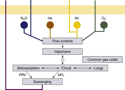
FIGURE 2-1 Organization of the anesthesia delivery system. APL, adjustable pressure-limiting; PRV, pressure relief valve.
Anesthesia Machine and Workstation
Gas delivery systems continue to evolve as advances in technology and safety are incorporated into current designs. The recent evolution can be traced through the voluntary consensus standards that have been developed with input from manufacturers, users, and other interested agencies. The current voluntary consensus standard that describes the features of a contemporary system is published by the American Society for Testing and Materials (ASTM).1 This document, standard F1850-00, published in March 2000 and reapproved in 2005, is entitled Standard Specification for Particular Requirements for Anesthesia Workstations and Their Components. It introduces the term “workstation” in distinction to “anesthesia (or gas) machine.” The anesthesia workstation is defined as a system for the administration of anesthesia to patients consistsing of the anesthesia gas supply device (i.e., the machine), ventilator, and monitoring and protection devices. This standard supersedes anesthesia machine standard F1161-88, published in 1989 by the ASTM.2 Standard F1161-88 had superseded the original anesthesia machine standard (Z79.8-1979) published in 1979 by the American National Standards Institute (ANSI).3 Like its predecessors, ASTM standard F1850-00 has been voluntarily adopted by anesthesia machine manufacturers. The standard is not mandated, but it is highly unlikely that a new manufacturer would build, or would a purchaser be likely to purchase, a workstation that did not comply with the current standards.
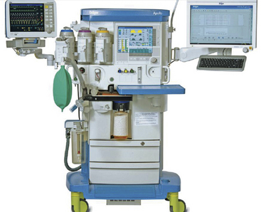
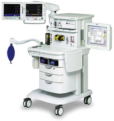
The evolution of the anesthesia workstation and advances in technology have led to many changes in design. Although basic operations remain the same, the components are more technologically advanced. For example, in many new models—such as the Dräger Apollo (Fig. 2-2) and the GE Aisys (Fig. 2-3)—the familiar rotameter tubes are replaced by virtual flowmeters displayed on a computer screen. The gas flow-control needle valves may be replaced by electronically controlled gas-mixing devices. This chapter describes the basic components and functions of a traditional anesthesia machine (i.e., the gas delivery device described in standard F1850-00) to enable the reader to appreciate some of the changes that have been made in the most recent models.
In the United States, the two largest manufacturers of gas delivery systems—machines, ventilators, vaporizers, and scavenging systems—are Draeger Medical Inc. (Telford, PA) and GE Healthcare (Waukesha, WI). This chapter reviews the features of a basic anesthesia delivery system, making reference to Dräger and GE (Datex-Ohmeda brand) products when appropriate. The flow of compressed gases from the point of entry into the machine, through the various components, and to the exit at the CGO is described. The function of each component is discussed so that the effects of failure of that component, as well as the rationale for the various machine checkout procedures, can be appreciated. This approach provides a framework from which to diagnose problems that arise with the machine. Of note, the individual machine or workstation manufacturer’s operator and service manuals represent the most comprehensive reference for any specific model of machine, and the reader is strongly encouraged to review the relevant manuals. The manufacturers also produce excellent educational materials,4-6 and a number of simulations are also available on the Internet.7-9
Basic Anesthesia Machine
Although older anesthesia machines were completely pneumatic and required only a supply of gas under pressure, contemporary machines are electronic and pneumatic and therefore must be connected to an electrical outlet for normal, uninterrupted operation. When the main ON/OFF switch is turned on, both the pneumatic and the electronic functions are enabled.
In the OFF position, most of the electronic functions of the workstation are disabled, with the exception of the battery charger that charges the backup battery and the convenience electrical outlets on the back of the workstation, which are used to supply power to additional monitors (e.g., bispectral index) or a heated, pressurized desflurane vaporizer. The pneumatic functions maintained are the oxygen supply to the oxygen flush system and, in most machines, the auxiliary oxygen flowmeter.
When the ON/OFF switch is turned to ON, the workstation electronics go through a powering-up protocol that may include an automated checkout procedure that lasts several minutes. In case of an emergency, the automated checkout can be bypassed, but a record of this is maintained in the workstation’s computer. In the ON position, the pneumatic functions permit delivery of an anesthetic gas mixture from the flowmeters and the concentration-calibrated vaporizer.
Pneumatic Systems
The gas flow arrangements of a basic two-gas anesthesia machine are shown in Figure 2-4. The machine receives each of the two basic gases, oxygen (O2) and nitrous oxide (N2O), from two supply sources: a tank or cylinder source and a pipeline source. The storage and supply of these gases to the operating room (OR) is described in Chapter 1.
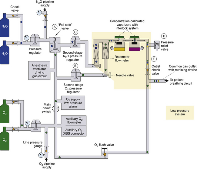
FIGURE 2-4 Schematic of flow arrangements of a generic contemporary anesthesia machine. A, The fail-safe valve in older GE Healthcare Datex-Ohmeda machines is termed a pressure-sensor shut-off valve; in more recent models, this valve has been replaced by a balance regulator. In Draeger Medical Inc., machines, the fail-safe valve is the oxygen failure protection device (OFPD). B, A second-stage oxygen pressure regulator is used in Datex-Ohmeda machines but not in Draeger Narkomed models. C, A second-stage nitrous oxide pressure regulator is used in Datex-Ohmeda Modulus machines that have the Link-25 Proportion Limiting System but not in Draeger machines. D, A pressure relief valve used in certain Datex-Ohmeda machines but not in Draeger machines. E, The outlet check valve used in Datex-Ohmeda machines, except Modulus II Plus and Modulus CD models, is not used in Draeger machines. The oxygen connection for the anesthesia ventilator driving gas circuit is downstream of the main ON/OFF switch in Draeger machines, as shown here. In Datex-Ohmeda machines, the takeoff is upstream of the main ON/OFF switch. DISS, diameter index safety system. (Modified from Checkout: a guide for preoperative inspection of an anesthesia machine. Park Ridge, IL, 1987, American Society of Anesthesiologists. Reproduced by permission of the American Society of Anesthesiologists, 520 N. Northwest Highway, Park Ridge, IL.)
The basic functions of any anesthesia machine are to receive compressed gases from their supplies and to create a gas mixture of known composition and flow rate at the CGO. The relation between pressure and flow is stated in Ohm’s law:
Controlling the flow of gases from high-pressure sources through the machine to exit the CGO at pressures approximating atmospheric pressure requires changes in pressure and/or resistance. Modern anesthesia machines also incorporate certain safety features designed to prevent the delivery of a hypoxic mixture to the patient circuit. These features include the oxygen supply pressure failure alarm, pressure sensor shut-off (“fail-safe”) system, and gas flow proportioning systems.
The anesthesia machine gas pathways have been conveniently divided by some authors into three systems10:
1. A high-pressure system that includes parts upstream of the first-stage regulator, where oxygen pressures are between 45 and 2200 psig
2. An intermediate pressure system that includes parts between the pipeline gas inlet/downstream outlet of the first-stage pressure regulator and the gas flow control valves, where oxygen pressures are between 55 and 16 psig
3. A low-pressure system that includes all parts downstream of the gas flow control valves, where pressures are normally slightly greater than atmospheric pressure
Other authors consider the high-pressure system to be simply all parts upstream of the gas flow control valves and the low-pressure system to be all parts downstream of the gas flow control valves. Indeed, this is in agreement with the system descriptions in the U.S. Food and Drug Administration 1993 preuse checkout recommendations.11 Either way, the most important definition is that of the low-pressure system, the one to which most preuse checkouts refer.
Oxygen Supply Sources: Pipelines and Cylinders
Pipeline oxygen is supplied to the wall outlets in the OR at a pressure of 50 to 55 psig. Gauge pressure is pressure above ambient atmospheric pressure. Ambient atmospheric pressure at sea level is usually considered to be equivalent to 760 mm Hg, or 14.7 psia. The wall outlet connectors are gas specific, but only within each manufacturer’s connector system. Thus an Ohmeda oxygen hose connector will not fit into an Ohmeda nitrous oxide wall outlet, but neither will it fit into an oxygen wall outlet in a Chemtron system. Thus the medical gas wall outlets and connectors are not interchangeable among the various gases or with the vacuum (Fig. 2-5). A color-coded hose conducts the pipeline oxygen from the wall outlet to the anesthesia machine’s oxygen inlet. At the machine end of the hose, the connectors are gas specific by a national standard (Fig. 2-6) known as the diameter index safety system (DISS) that ensures that the correct gas enters the correct part of the anesthesia machine.12 To standardize connections, many institutions are replacing the manufacturer’s gas-specific wall outlets with DISS connectors (Fig. 2-7).
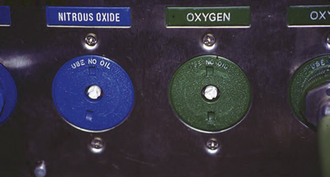
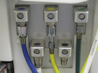
FIGURE 2-6 Diameter index safety system hose connections to workstation pipeline supply connections.
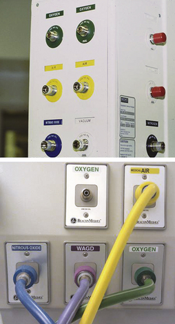
FIGURE 2-7 Diameter index safety system wall connectors. Blue is nitrous oxide, green is oxygen, yellow is room air, white is the hospital vacuum, and purple is the waste gas scavenging vacuum.
The machine’s oxygen pipeline inlet incorporates a check valve that prevents leakage of oxygen from the machine if the pipeline is not connected and oxygen tanks are in use (Fig. 2-8). Failure of this valve would cause oxygen to leak from the machine. Upstream of the pipeline inlet in the machine is a pressure gauge that displays the pipeline gas supply pressure (see Fig. 2-4).
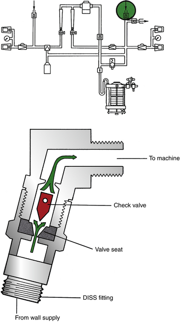
FIGURE 2-8 Machine pipeline inlet check valve. The flow of oxygen from the wall supply opens the pipeline inlet valve. If the wall supply hose were disconnected with the tank oxygen in use, the pressure of oxygen in the machine would force the check valve to its seated position, preventing loss of oxygen via this connector. DISS, diameter index safety system. (From Bowie E, Huffman LM: The anesthesia machine: essentials for understanding. Madison, WI, 1985, GE Datex-Ohmeda.)
Tank oxygen is supplied to the machine from the back-up E-cylinders attached via the oxygen hanger yokes (Fig. 2-9). The medical gas pin index safety system ensures that only an oxygen tank fits correctly into an oxygen hanger yoke (see Chapter 1).13 Although manipulation is possible, a medical gas cylinder should never be forced to fit into a hanger yoke.
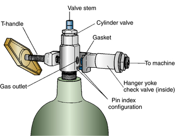
FIGURE 2-9 Hanger yoke for an oxygen tank showing the pin-indexed safety system. (From Bowie E, Huffman LM: The anesthesia machine: essentials for understanding. Madison, WI, 1985, GE Datex-Ohmeda.)
The pressure in a full oxygen tank is normally between 1900 and 2200 psig. Oxygen enters the hanger yoke at this pressure and then passes through a strainer nipple (Fig. 2-10) designed to prevent dirt or other particles from entering the machine. The oxygen then flows past a hanger yoke (“floating”) check valve to enter the anesthesia machine at high pressure.
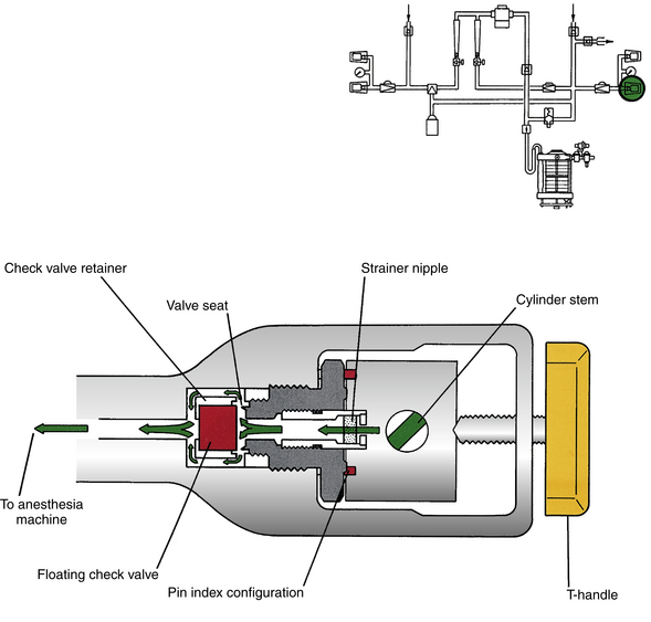
FIGURE 2-10 Cross-section of hanger yoke showing flow of oxygen from the tank through the strainer nipple into the machine. (From Bowie E, Huffman LM: The anesthesia machine: essentials for understanding. Madison, WI, 1985, GE Datex-Ohmeda.)
Several considerations apply before a tank is hung in a yoke. First, the plastic wrapper that surrounds the tank valve must be removed. Then the valve is opened slowly, or “cracked,” to allow gas to exit the tank and blow out any particles of dirt that may be lodged in the outlet. The tank is then hung in the yoke. The gas outlet hole is aligned with the strainer nipple, and the two yoke pins are aligned with the corresponding holes in the tank. The tank should never be turned through 180 degrees and then hung in the yoke because a tightened T-handle screw might damage the tank valve-stem pressure relief mechanism (see Chapter 1). Although changing the oxygen tank on an anesthesia machine may seem straightforward, one study showed that a significant number of senior residents in a simulator could not perform this task satisfactorily, possibly because it is generally performed by technical staff.14 Checking to see that a backup tank contains sufficient oxygen is an important part of the preuse checkout and also ensures that a tank wrench is available for opening and closing the tank valve.15
Oxygen is also available in freestanding E-size tanks pressurized to 3000 psig (1000 L gaseous oxygen) that incorporate a regulator that delivers oxygen at 50 psig to a DISS connector. Thus, if the pipeline fails, the machine’s oxygen hose could be connected to this tank outlet if the wall end of the hose has a DISS fitting (Figs. 2-11 and 2-12).
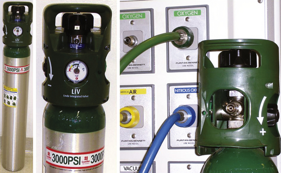
FIGURE 2-11 Left, Oxygen tank pressurized to 3000 psig when filled. Right, The tank valve incorporates a regulator with a diameter index safety system (DISS) oxygen connector that supplies oxygen at 50 psig. The anesthesia machine oxygen hose is shown connected to a DISS wall outlet for oxygen.
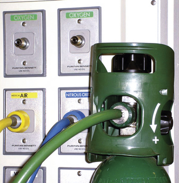
FIGURE 2-12 If the wall oxygen supply fails, the machine’s oxygen hose can be disconnected from the wall and reconnected to the 50 psig diameter index safety system connector on the oxygen tank shown in Figure 2-11.
Some anesthesia machines have two hanger yokes for oxygen. Once oxygen has passed through the check valve, the two hanger yokes are connected by high-pressure tubing, to which an oxygen pressure gauge is also connected (see Fig. 2-16). This gauge measures the pressure of the oxygen cylinder supply connected via hanger yokes. On many machines, both yokes may share one pressure gauge. In this case, to measure the tank pressure, the pipeline supply is first disconnected from the machine and both tanks are turned off. Next, the oxygen flush button is depressed to drain all oxygen from the machine, and the tank and pipeline gauge readings should both fall to zero. One tank is then turned on, and its pressure is noted on the gauge. The tank is then turned off, the oxygen flush button is again depressed, and the tank gauge pressure falls to zero. The second tank is then opened and its pressure noted. The second tank is then closed, and the oxygen flush button is depressed. The pipeline connector is then reattached to the wall oxygen outlet.
As previously noted, a check valve in each oxygen hanger yoke is designed to prevent oxygen from flowing out of the machine through the strainer nipple. This valve prevents loss of gas via the hanger yoke when no oxygen tank is hanging in one yoke, but an oxygen tank in the other yoke is being used to supply the machine (see Fig. 2-16). These valves also prevent transfilling of one oxygen tank to the other, if two tanks are hanging on the machine and both are on. In other words, without a check valve, oxygen would tend to flow from the full tank to the empty one if both were open. If the check valve were not present, the transfilling and sudden compression of oxygen into the empty cylinder could cause a rapid temperature rise in the pipes, gauge, and tank with an associated risk of fire. This is known as an adiabatic change, in which the state of a gas is altered without the gas being permitted to exchange heat energy with its surroundings.5
If there are two hanger yokes for oxygen but only one tank is hanging, a yoke plug should be inserted and tightened in the empty yoke. Thus, if an oxygen check valve leaks, loss of oxygen from the empty hanger yoke is prevented by the yoke plug (Fig. 2-13).
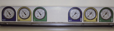
The pressure gauges used in the traditional machine to measure pipeline supply pressure or tank supply pressure (Fig. 2-14) are of the Bourdon tube design. In principle, the Bourdon tube is a coiled metal tube sealed at its inner end and open to the gas pressure at its outer end (see Chapter 9). As gas pressure rises, the coiled tube tends to straighten. A pointer attached to the inner-sealed end thereby moves across a scale calibrated in units of pressure. If the Bourdon tube were to burst, the inside of the gauge could be exposed to high pressure. The gauge is therefore constructed with a special heavy glass window and a mechanism designed to act as a pressure fuse so that gas is released from the back of the casing if the pressure suddenly rises. The cylinder and pipeline pressure gauges for the gases supplied to the machine are generally situated in a panel on the front of the anesthesia machine (see Fig. 2-14). In some workstations, pressure is sensed by a pressure transducer and is displayed on a screen (Fig. 2-15).
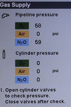
FIGURE 2-14 Gas supply pressure gauges on the front panel of an anesthesia workstation. The three on the left display pipeline supply pressures; those on the right display cylinder supply pressures (note cylinder symbols).
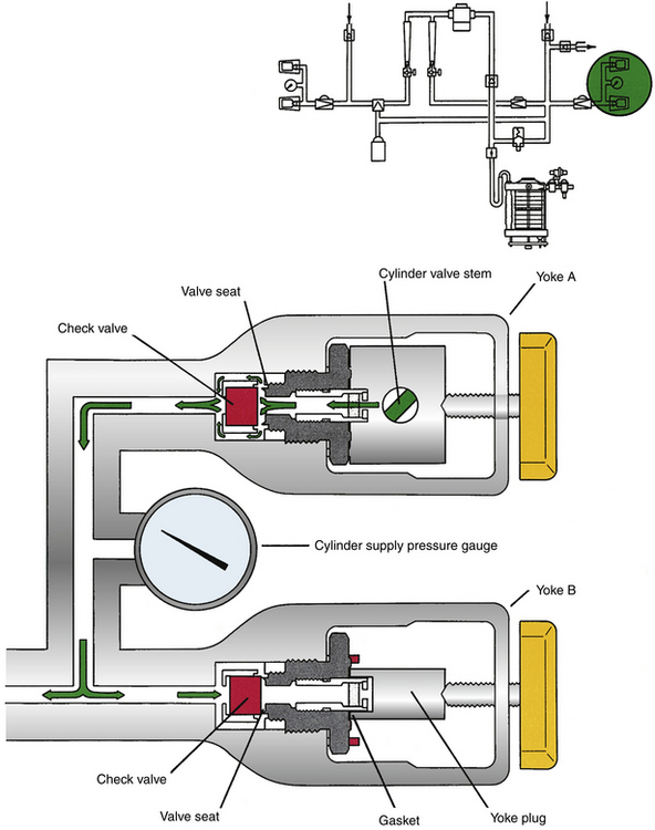
FIGURE 2-15 Pipeline and cylinder gas supply pressures in this workstation are measured by pressure transducers and are displayed digitally on the workstation screen during checkout.
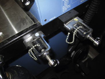
FIGURE 2-16 Double-hanger yoke assembly with oxygen tank hanging in yoke A. Gas flows into the machine via the floating check valve. Gas cannot escape via yoke B because the oxygen pressure closes the check valve. If gas should leak past the check valve, its flow is prevented by the yoke plug, which has been tightened into yoke B, occluding the yoke nipple. (From Bowie E, Huffman LM: The anesthesia machine: essentials for understanding. Madison, WI, 1985, GE Datex-Ohmeda.)
Cylinder Pressure Regulator
A pressure regulator is a device that converts a variable, high-input gas pressure to a constant, lower output pressure. As previously mentioned, tank oxygen enters the machine at pressures of up to 2200 psig depending on how full the tank is. These variable, high-input pressures are reduced to a constant, lower output pressure of 45 psig by the oxygen cylinder pressure regulator, sometimes termed the first-stage regulator (see Fig. 2-4). As noted in Figure 2-16, the tank oxygen from both yokes flows to a common pathway leading to the inlet of the regulator. One regulator serves the two oxygen hanger yokes and is located under the machine’s work surface.
The principles of action of the regulator are shown in Figure 2-17.16,17 This is described as a direct-acting regulator because the high-pressure gas tends to open the valve. In an indirect-acting regulator, the high-pressure gas tends to close the valve. In essence, the regulator works by balancing the force of a spring against the forces that result from gas pressures acting on a diaphragm. Oxygen at tank pressure enters the high-pressure inlet and is applied over a small area to the valve seat (see Fig. 2-17), and the valve opening is opposed by a return spring. The valve seat is connected by a thrust pin to a diaphragm in the low-pressure chamber of the regulator. Upward movement of the diaphragm is opposed by a spring that exerts a pressure of 45 psig on the diaphragm. The adjustment of this spring is such that oxygen may flow from the high-pressure inlet across the valve seat and into the low-pressure chamber. If pressure in the low-pressure chamber exceeds 45 psig, the diaphragm moves upward and closes the valve opening, halting the flow of oxygen from high- to low-pressure chambers, until the gas pressure exerted on the diaphragm falls below 45 psig. The pressure in the low-pressure chamber and the low-pressure piping of the machine when supplied by the tanks is thereby kept at a constant 45 psig. A cessation of flow from the low-pressure chamber, such as would occur if the oxygen flow control valve meter were closed, causes pressure to build up here, closing the regulator valve and halting the flow of gas from the cylinder into the regulator.
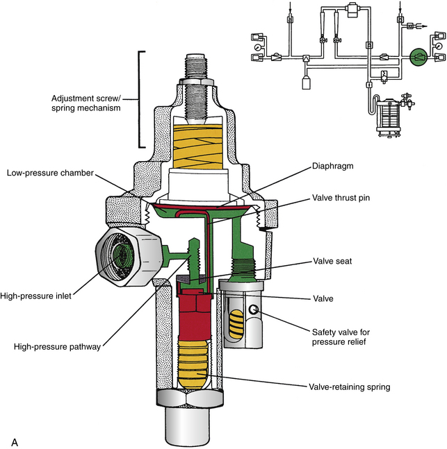
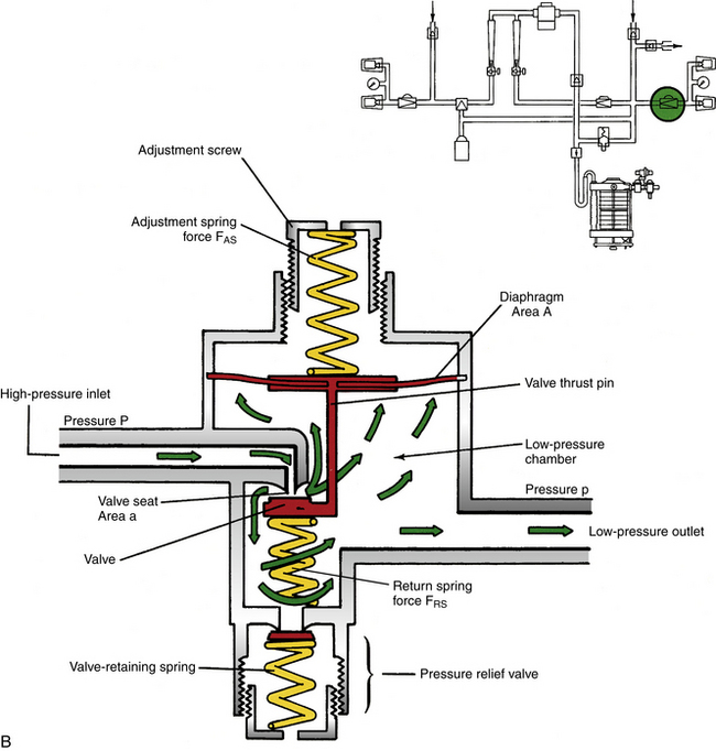
FIGURE 2-17 A, Schematic of a direct-acting oxygen pressure regulator.B, An inside look at the regulator as oxygen pressure is reduced. In principle, the regulator functions by balancing forces acting on the diaphragm. Gas under high pressure (P) enters the regulator and is applied to the valve over the area of the seat (a). Because Force = Pressure × Area, the force resulting from high-pressure gas is P × a. Valve opening is initially opposed by the force of the return spring, FRS. Because of the small area of the valve orifice, gas flowing through it enters the next chamber at a lower pressure (p). This lower pressure is applied over the large area of the diaphragm (A) at a force of p × A. Upward movement of the diaphragm is opposed by the force of the adjustment spring, FAS. The valve and diaphragm are connected by a thrust pin and move as one unit according to the forces applied in either direction. In equilibrium, the forces acting on the diaphragm are equal: (P × a) + FAS = (p × A) + FRS. The reduced pressure p = [(FAS − FRS) + (P × a)]/A. The regulator is designed such that p is fairly constant despite changes in P. (From Bowie E, Huffman LM: The anesthesia machine: essentials for understanding. Madison, WI, 1985, GE Datex-Ohmeda.)
Failure of the pressure reduction function of a regulator can transmit excessively high pressure (up to 2200 psig) to the machine’s low-pressure system (see Fig. 2-17). To protect against such occurrences, the regulator incorporates a pressure relief valve in the low-pressure chamber in which excess pressures are vented to the atmosphere. If the diaphragm were to rupture or develop a hole, the regulator would fail and gas would escape around the adjustment screw and spring. The high flow of escaping oxygen makes a loud sound, alerting the anesthesiologist to the possibility of a regulator failure. Such a hole represents a significant leak in the high-pressure system or intermediate-pressure system through which oxygen would be lost. Figure 2-4 shows that even if the tanks were turned off and the pipeline supply were in use, a ruptured diaphragm in the regulator would cause loss of oxygen from the machine’s high-pressure system or intermediate-pressure system and a possible failure of oxygen supply to the flowmeters. Such a machine should be withdrawn from service until the problem has been corrected by an authorized service technician. Meanwhile, oxygen may be supplied to the patient by a self-inflating (Ambu) bag connected to a portable supply of oxygen, such as a transport oxygen cylinder with its own pressure-reducing valve and flowmeter.
Oxygen Supply to the Intermediate-Pressure System
Oxygen is typically supplied to the machine’s pipeline connector inlet at pressures of 50 to 55 psig, whereas the tank oxygen supply is regulated to enter at 40 to 45 psig. This difference in supply pressures is deliberate; if the pipeline is connected and the oxygen tanks are open, oxygen is preferentially drawn from the pipeline supply. This is because the higher pressure (50 to 55 psig) from the pipeline supply closes the valve in the first-stage oxygen regulator, thereby preventing the flow of oxygen from the tank. However, at times, such as during heavy oxygen use, the pipeline pressure may fall below 45 psig. In this case, oxygen would be drawn from the tanks if they were open. Thus, once the tank supply has been checked, it should be turned off to prevent loss of the backup oxygen supply. Also, if the tank is left open, oxygen might leak around the plastic washer between the tank and the yoke.
An awareness of the differential in supply pressures of oxygen to the machine is essential.14 If a pipeline crossover is suspected, such as when a hypoxic gas is flowing through the oxygen pipeline to the piping in the machine, the machine must be disconnected from the pipeline supply if the backup oxygen supply is to be used. For example, if a hypoxic gas (e.g., nitrous oxide) is accidentally used to supply the oxygen pipeline at a supply pressure of greater than 45 psig, the anesthesiologist cannot deliver the true oxygen from the backup tanks because the pressure from the wall supply is greater than that from the first-stage oxygen regulator.
Flow Pathways For Oxygen in the Intermediate-Pressure System
Having entered the machine intermediate-pressure system at 50 to 55 psig (pipeline) or 40 to 45 psig (tank first-stage regulator), oxygen can flow or pressurize in several directions.
Oxygen Flush
As soon as any oxygen supply is connected to the machine, pressing the oxygen flush button results in a flow of oxygen to the machine CGO at 35 to 75 L/min.1 Figure 2-18 shows that this pathway bypasses the main pneumatic and electronic ON/OFF switches and that the pressure at the CGO could increase the supply pressure to the machine unless some pressure relief mechanism is present. To avoid barotrauma in a patient, extreme caution is therefore necessary when oxygen flush is used. Contemporary machines incorporate a pressure-limiting device to prevent such potentially harmful pressures, particularly if the flush is activated during the inspiratory phase of positive-pressure ventilation (see Chapter 6).
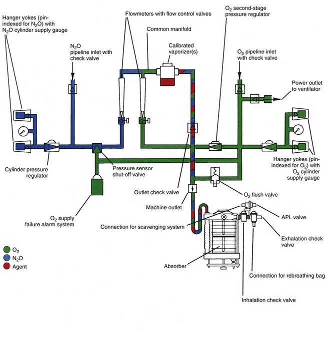
FIGURE 2-18 Schematic showing principal pathways for oxygen flow or pressurization in a basic GE Healthcare Datex-Ohmeda machine. APL, adjustable pressure-limiting valve. (From Bowie E, Huffman LM: The anesthesia machine: essentials for understanding. Madison, WI, 1985, GE Datex-Ohmeda.)
The workstation standard requires that the oxygen flush valve be self-closing and designed to minimize unintended operation by equipment or personnel.1 A modern design for an oxygen flush button is shown in Figure 2-19; note that the button is recessed in a housing to prevent accidental depression and that the valve is self-closing.
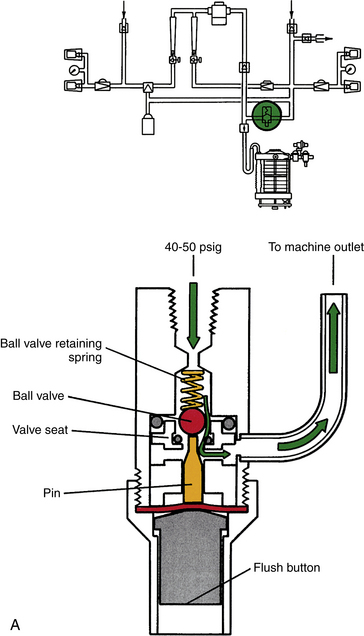
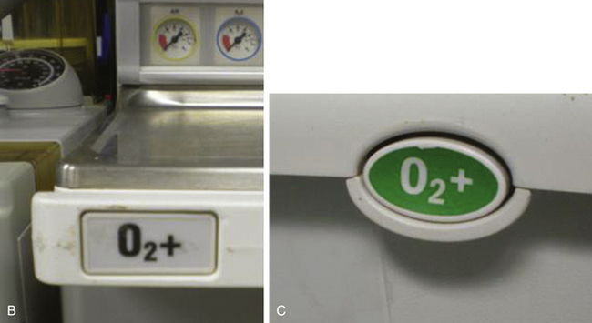
FIGURE 2-19 A, Schematic of oxygen flush valve in closed position. Note that it is recessed to prevent accidental activation. When depressed, oxygen flows from the common gas outlet at a rate of 35 to 75 L/min. Depending on the pressure relief arrangements, the oxygen may be delivered at pipeline supply pressure. (From Bowie E, Huffman LM: The anesthesia machine: essentials for understanding. Madison, WI, 1985, GE Datex-Ohmeda.) B and C, Examples of oxygen flush valve buttons. Note that they are flush with the front of the workstation to avoid accidental activation.
Auxiliary Oxygen Flowmeter
Most contemporary machines incorporate an auxiliary oxygen flowmeter that delivers oxygen, usually via a pressure-reducing regulator, to an accessible nipple at flows typically up to 10 L/min (Fig. 2-20). This is the source used to connect devices that deliver supplemental oxygen to a nasal cannula, face mask, or self-inflating reservoir bag, such as an Ambu bag. Similar to the oxygen flush, this flowmeter is active when the machine’s main ON/OFF switch is off.
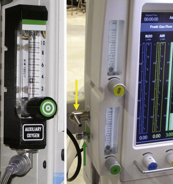
FIGURE 2-20 Left, Auxiliary oxygen flowmeter and delivery nipple. Flow can be adjusted up to 10 L/min. Pressure available varies according to the setting of the pressure regulator. Note that if a hypoxic gas enters the oxygen inlet of the machine, the same gas will be delivered to the auxiliary oxygen flowmeter. There is no oxygen analyzer to confirm that the gas flowing from this outlet is, in fact, oxygen. Right, A machine with both auxiliary oxygen and auxiliary air flowmeters supplies gas at flows of up to 15 L/min to the auxiliary nipple (yellow arrow). The auxiliary air-oxygen mixture is used when a lower fraction of inspired oxygen is needed for delivery by nasal cannula, such as when a fire hazard is present. The green arrow indicates a diameter index safety system 55-psig oxygen connector.
Auxiliary Diameter Index Safety System Oxygen Source
Many workstations provide an auxiliary source of oxygen at pipeline pressure (50 to 55 psig) via a DISS connector while the machine is connected to a pipeline supply. An available DISS connector can be beneficial if the machine’s oxygen hose and the wall oxygen outlets have quick-connect fittings (Figs. 2-20 and 2-21). The outlet can be used to drive a Sanders-type jet ventilator,18 a Venturi-based suctioning device, or other device that requires pipeline oxygen pressure.
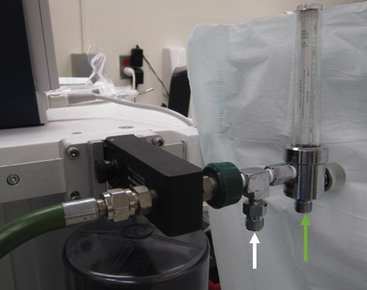
FIGURE 2-21 An auxiliary diameter index safety system 55-psig oxygen outlet (white arrow) supplied from the machine’s intermediate-pressure system for oxygen can be used to drive a Sanders-type jet ventilating system via an inline pressure-reducing valve and toggle switch. The auxiliary oxygen flowmeter is combined in this assembly. An integral pressure regulator reduces pressure to the auxiliary oxygen flowmeter so that oxygen is delivered at much lower pressures at the outlet of the flowmeter (green arrow).
Unless otherwise stated, oxygen flows to, or pressurizes, the components that follow it only when the main ON/OFF switch is in the ON position (see Fig. 2-4).
Oxygen Supply Failure Alarm System
Oxygen pressurizes an oxygen supply failure alarm system such that if the supply pressure falls, usually below 30 psig, an alarm is triggered (see Figs. 2-4 and 2-18). Some older machine models use a canister pressurized with oxygen that emits an audible alarm for at least 7 seconds when the pressure falls below the threshold. Contemporary machines use a pressure-operated electrical switch that ensures a continuous audible alarm when the oxygen supply pressure falls below the threshold setting.
The workstation standard requires that whenever oxygen supply pressure falls below the manufacturer-specified threshold, a medium-priority alarm is activated within 5 seconds. After the alarm has been activated, it may be released by the user for a period of up to 120 seconds but is automatically reset after restoration of oxygen supply pressure to a level above the alarm threshold.1
Pneumatically Powered Anesthesia Ventilator
Oxygen at a pressure of 50 to 55 psig (pipeline) or 45 psig (tanks) is used as the power source for pneumatically driven anesthesia ventilators, such as the GE Datex-Ohmeda 7000, 7800, and 7900 series and the Dräger AV-E. In Datex-Ohmeda machines, when the ventilator connection is made, the valve opens to permit compressed oxygen to flow to the ventilator (Fig. 2-22). In Dräger Narkomed 2, 3, and 4 machines, the oxygen takeoff to drive the ventilator is downstream of the machine main ON/OFF switch, so the ventilator cannot be operated if the machine is turned off (see Fig. 2-4). In older model Ohmeda machines, the oxygen takeoff to the ventilator circuit is upstream of the main ON/OFF switch.
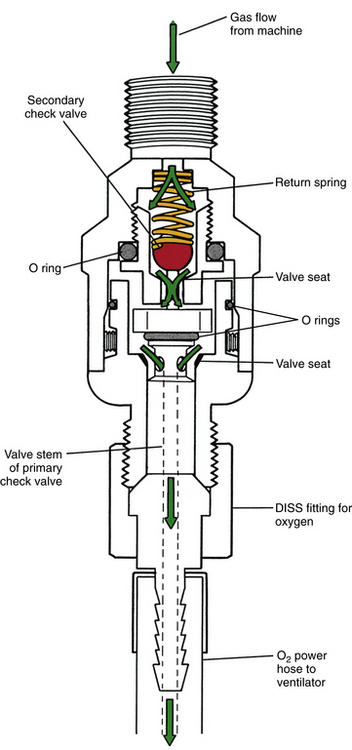
FIGURE 2-22 Oxygen power outlet to a ventilator. While the diameter-indexed safety system (DISS) fitting on the ventilator’s oxygen supply hose is screwed on to the connector, the valve is lifted from its seat, permitting oxygen to flow to the ventilator’s power hose. (From Bowie E, Huffman LM: The anesthesia machine: essentials for understanding. Madison, WI, 1985, GE Datex-Ohmeda.)
During operation, pneumatically powered ventilators consume large quantities of oxygen. If the machine is being supplied by a backup E-cylinder, that cylinder’s contents are rapidly exhausted because it is also supplying oxygen to the patient circuit.19-21 In ventilators that use 100% oxygen as the driving gas—such as the Datex-Ohmeda 7000, 7800, and 7900 series—the ventilator oxygen consumption is in excess of the minute ventilation set on the ventilator (i.e., Rate × Bellows tidal volume). The Dräger AV-E is more economical in terms of oxygen because it uses oxygen to drive a Venturi that entrains air. The air-oxygen mixture is then used as the final driving gas mixture that enters the ventilator bellows housing (see Chapter 6).
In some workstations, if the pressurized supply of oxygen is lost but air is not, the ventilator may switch to being powered by compressed air (Fig. 2-23). Of course, this is not an issue in workstations that use a piston ventilator powered by an electric motor.
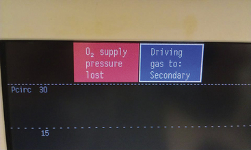
FIGURE 2-23 If the oxygen supply to the workstation fails but the air supply is maintained, the workstation can switch to the secondary gas (air) to drive the bellows ventilator. An alert is displayed on the workstation screen. Air can be delivered at the common gas outlet as set on the air flowmeter.
Pressure Sensor Shut-off (Fail-Safe) Valves
When the main ON/OFF switch is in the ON position, oxygen pressurizes and holds open a pressure-sensor shut-off valve. These valves reduce or interrupt the supply of nitrous oxide and other hypoxic gases (e.g., carbon dioxide and helium), but not air, to their flowmeters if the oxygen supply pressure falls below the threshold setting. This valve, in relation to control of the nitrous oxide supply, is the fail-safe system designed to prevent the unintentional delivery of a hypoxic mixture from the flowmeters.
The action of turning the machine’s main ON/OFF switch to the OFF position allows the oxygen pressure in parts of the machine downstream of the switch (normally 45 to 55 psig) to be vented to the atmosphere. The resulting decrease in oxygen pressure causes the fail-safe valves to interrupt the supply of all other gases, usually with the exception of air, to their flow-control valves. The design of the fail-safe system differs between the Dräger and Datex-Ohmeda machines.
In older model Datex-Ohmeda machines, when the oxygen supply pressure in the intermediate-pressure system falls below 20 to 25 psig, the flow of nitrous oxide to its flowmeters is completely interrupted. The pressure sensor shut-off valve used by the older model Datex-Ohmeda machines is an all-or-nothing threshold arrangement—open at oxygen pressures greater than 20 to 25 psig and closed at pressures below 20 psig (Fig. 2-24).22,23
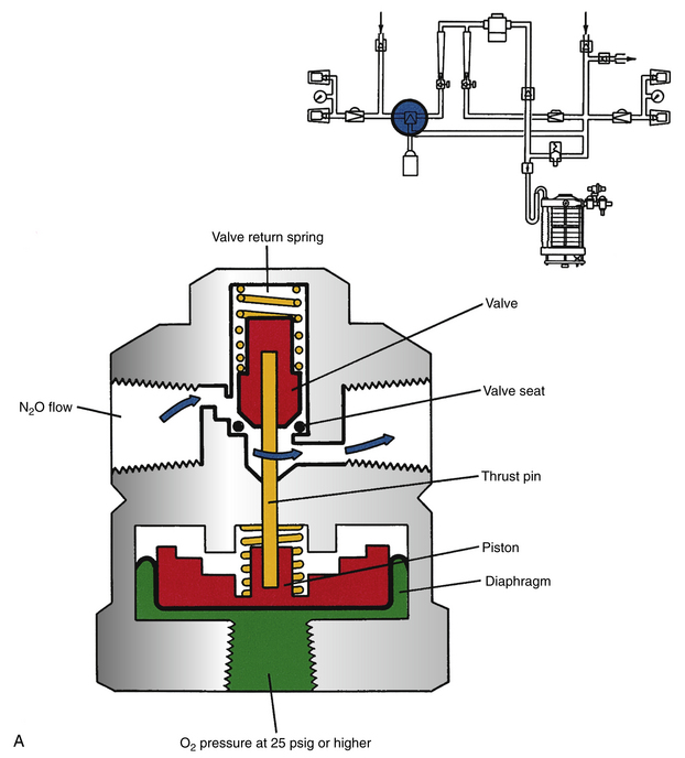
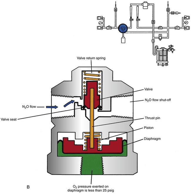
FIGURE 2-24 A, GE Healthcare Datex-Ohmeda pressure sensor shut-off (“fail-safe”) valve in a traditional machine. If oxygen supply pressure on the diaphragm exceeds the threshold, in this case 25 psig, the valve is lifted from its seat and nitrous oxide can flow to its flowmeter. B, If the oxygen supply pressure falls below the threshold setting for the valve return spring pressure, the valve is no longer held off its seat and interrupts the flow of nitrous oxide to its flowmeter. A pressure sensor shut-off valve is present for each gas (but not oxygen) supplied to the machine. In the GE Healthcare Aestiva/5 machine, a balancing valve replaces the pressure sensor shut-off valve. This is a variable valve, rather than an open or shut valve. (From Bowie E, Huffman LM: The anesthesia machine: essentials for understanding. Madison, WI, 1985, GE-Datex-Ohmeda.)
In the Datex-Ohmeda Aestiva/5 workstation, a more recent model, the fail-safe valve is not an all-or-nothing design; it is a variable valve in a balance regulator, in which the secondary regulator for oxygen reduces the pressure to approximately 30 psig in the intermediate-pressure system (see Fig. 2-4). The oxygen pressure is then piloted to the balance regulator, where it is applied to the oxygen side of the regulated diaphragm. If the pressure of oxygen is sufficient, the diaphragm pushes against a mechanism that opens the flow pathway for nitrous oxide. If the oxygen piloting pressure decreases, the mechanism begins to close off the pathway for nitrous oxide in proportion to the decrease in piloted oxygen pressure. The balance regulator for nitrous oxide completely closes when the pressure of oxygen falls to 0.5 psig. Balance regulators for heliox and carbon dioxide interrupt the flow of these gases when the piloted oxygen pressure falls below 10 psig.4
The fail-safe valve in Narkomed 2, 3, and 4 machines is called an oxygen failure protection device (OFPD) and, as in the Datex-Ohmeda systems, there is one for each of the gases supplied to the machine (Fig. 2-25). As the oxygen supply pressure falls and the flow of oxygen from the machine’s flowmeter decreases, the OFPDs proportionately reduce the supply pressure of other gases to their flowmeters. The supply of nitrous oxide and other gases is thereby completely interrupted when the oxygen supply pressure falls to below 12 ± 4 psig.24 Therefore, the OFPD functions similarly to the balance regulator in the Datex-Ohmeda Aestiva/5.
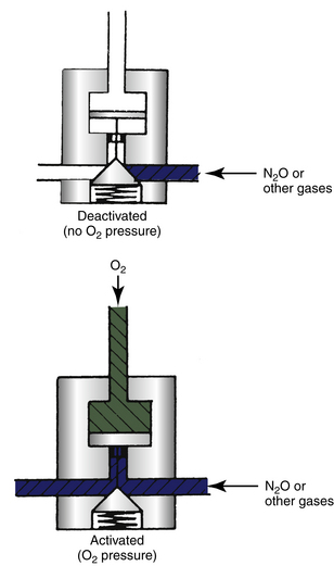
FIGURE 2-25 Draeger Medical Inc. oxygen failure protection device (OFPD). As the supply pressure of oxygen decreases from the normal value of 55 psig, the OFPD proportionately decreases the nitrous oxide supply pressure to the nitrous oxide flowmeter; the flow is interrupted completely when oxygen supply pressure is 12 ± 4 psig. There is an OFPD for each gas (but not oxygen) supplied to the machine; thus a four-gas machine would have three OFPDs. This is a variable fail-safe valve. (Courtesy Dräger Medical, Telford, PA.)
Both fail-safe valve designs ensure that at low- or zero-oxygen supply pressures, only oxygen may be delivered to the machine’s CGO. However, as long as the oxygen supply pressure is adequate, other gases may flow to their flowmeters. The fail-safe system does not ensure oxygen flow at its flowmeter, only a supply pressure to the oxygen flowmeter. Thus a normally functioning fail-safe system would permit flow of 100% nitrous oxide, provided the machine has an adequate oxygen supply pressure. The term “fail-safe” therefore represents something of a misnomer because it does not ensure oxygen flow (Fig. 2-26).
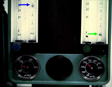
FIGURE 2-26 Limitation of the fail-safe system. In this machine, because the supply pressure of oxygen is adequate (2000 psig from the tank and therefore 45 psig in the machine), nitrous oxide may flow to its flowmeter and beyond (4 L/min; blue arrow) even though the oxygen flow control valve is turned off and no oxygen is flowing (green arrow). The term fail-safe is therefore somewhat of a misnomer; the system cannot prevent delivery of a hypoxic gas mixture because the valve is pressure sensitive rather than flow sensitive.
Flowmeters
Oxygen flows to the oxygen flow control valve and flowmeter(s), traditionally rotameters. Supply pressure to the oxygen flowmeters differs in Datex-Ohmeda and Dräger machines. In contemporary Datex-Ohmeda machines, the oxygen supply pressure to the flowmeters is regulated to a constant, lower pressure—14 to 30 psig, depending upon the model—by a second-stage regulator. This regulator (see Figs. 2-4 and 2-18) ensures a constant supply pressure to the Datex-Ohmeda oxygen flowmeter. Thus, even if the oxygen supply pressure to the machine decreases below 45 to 50 psig, as long as it exceeds the set second-stage regulated downstream pressure, the flow setting on the oxygen flowmeter is maintained. Without this second-stage regulator, if the oxygen supply pressure were to fall, the oxygen flow at the flowmeter would decrease. If another gas (e.g., nitrous oxide) was also being used, a hypoxic gas mixture could result at the flowmeter manifold.
The second-stage oxygen regulator used in Datex-Ohmeda machines is similar in terms of principle of operation to that of the first-stage regulator (see Fig. 2-17). However, because it normally handles lower pressures than the first-stage regulator, it neither requires nor incorporates a pressure relief valve.
Narkomed anesthesia machines do not use a second-stage oxygen pressure-regulator valve (see Fig. 2-4). These machines have OFPDs that interface the supply pressure of oxygen with that of nitrous oxide and the other gases supplied to the machine.6 The OFPD consists of a seat-nozzle assembly connected to a spring-loaded piston (see Fig. 2-25). When deactivated, the spring is expanded, forcing the nozzle against the seat so that no gas can flow through the device to the flowmeter. As oxygen pressure increases, it is applied to the piston, which in turn forces the nozzle away from its seat so that gas can flow through the OFPD. The OFPD responds to oxygen pressure changes such that as pressure falls, the other gas flows will fall in proportion. When the oxygen supply pressure is less than 12 ± 4 psig, the OFPD is completely closed.24 A decrease in oxygen supply pressure causes a proportionate decrease in the supply pressures of each of the other gases to their flowmeters. As the oxygen supply pressure and flow decrease, all other gas flows are decreased in proportion to prevent the creation of a hypoxic gas mixture at the flowmeter level (see the preceding section). The operation of the OFPD can be demonstrated. With the Narkomed machine supplied from pipeline oxygen (55 psig), set 6 L/min flows of both nitrous oxide and oxygen; if the pipeline oxygen is disconnected and the tank oxygen supply is opened (45 psig), flow of both oxygen and nitrous oxide will be observed to have decreased at the rotameters.
The use (GE Datex-Ohmeda) or nonuse (Dräger) of a second-stage oxygen regulator affects the total gas flow emerging from the CGO of the machine if the oxygen supply pressure falls. In an older model Datex-Ohmeda machine, as long as the oxygen supply pressure exceeds the set threshold of the second-stage regulator, all gas flows are maintained at the original flowmeter settings. In a Narkomed machine, if the oxygen supply pressure falls from normal (45 to 55 psig), all gas flows decrease in proportion via the OFPDs. A decrease in total gas flow from the machine’s CGO might result in rebreathing, depending on the breathing circuit in use.
Nitrous Oxide
Like oxygen, N2O may be supplied to the machine either from the pipeline system at 50 to 55 psig or from the backup E-cylinder supply on the machine itself. Nitrous oxide from the tank supply enters the nitrous oxide–specific yokes at pressures of up to 745 psig (at 20° C); it then passes through a first-stage regulator similar to that for oxygen, which reduces this pressure to 40 to 45 psig (see Fig. 2-4). The pin index safety system is designed to ensure that only a nitrous oxide tank can hang in a nitrous oxide hanger yoke. As with oxygen, a check valve in each yoke prevents the backflow of nitrous oxide if no tank is hung in the yoke (see Fig. 2-8).
The nitrous oxide pipeline is supplied from liquid nitrous oxide or from banks of large tanks of nitrous oxide, usually H-cylinders (see Chapter 1). The pressure in the pipeline is regulated to 50 to 55 psig to supply the outlets in the OR. Once it enters the anesthesia machine, nitrous oxide must flow past the pressure-sensor shut-off (fail-safe) valve to reach its flow control valve and flowmeter.
In Datex-Ohmeda anesthesia machines that have the Link-25 proportion limiting system, a second-stage nitrous oxide regulator further reduces gas pressure so that nitrous oxide is supplied to its flowmeter at a nominal 26 psig (Fig. 2-4).22 The actual downstream pressure of this second-stage nitrous oxide regulator is adjusted at the factory or by an authorized field service representative to ensure correct functioning of the proportioning system.
Other Medical Gases
Some anesthesia machines are designed to deliver other gases such as air, helium, heliox, and even carbon dioxide (Figs. 2-27 and 2-28). If another medical gas is supplied to the machine, the arrangements are similar to those for the nitrous oxide supply. Thus, there is a DISS gas-specific connector for a pipeline supply and a pin-indexed gas-specific hanger yoke for the tank supply. Supply pressure gauges are provided for the supply source (pipeline or tank), and a fail-safe valve controls the flow of each gas to its flowmeter, with the possible exception of air, according to the oxygen supply pressure in the machine.
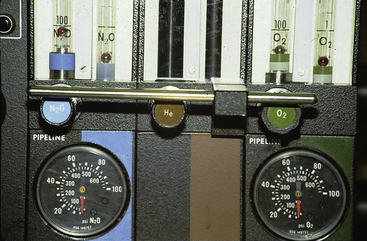
FIGURE 2-27 Potential for a hyperoxic mixture. This machine is designed to deliver oxygen, nitrous oxide, and helium. If it were set to deliver a mixture of oxygen at 1 L/min and helium at 3 L/min (i.e., 25% O2/75% He) for laser surgery of the airway and the helium tank became empty, the machine would deliver 100% oxygen and create a potential fire hazard. In this case, an oxygen analyzer with a high-concentration alarm is essential. Newer machines are designed to deliver a mixture of helium and oxygen (heliox).
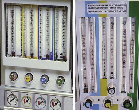
FIGURE 2-28 Flowmeter banks on a four-gas Datex-Ohmeda (GE Healthcare, Waukesha, WI) anesthesia machine (left) and a four-gas Dräger Medical (Telford, PA) machine (right). Flowmeters for each gas are arranged in series. The oxygen flows first through a rotameter, where low flows (<1 L/min) are measured, and then through a rotameter, where high flows (<10 L/min) are measured. In the United States, the oxygen flowmeters are on the right side of the flowmeter bank when viewed from the front. One gas flow control knob is present for each gas, even if there are two (low and high) flowmeter tubes for that gas.
Anesthesia Machine Gas Piping System
Within the anesthesia machine, piping conducts compressed gases from point of entry, through the various components, and to the CGO. The workstation standard requires that this piping be capable of withstanding four times the intended service pressure without rupturing.1 It further specifies that between the cylinders or the pipeline inlet and the flow control valves, the maximum leakage of each gas cannot exceed 10 mL/min at normal working pressure (30 mL/min at a pressure of 30 cm H2O with the vaporizers in both the ON and OFF positions).1 The standard requires that gas piping connectors be noninterchangeable or that the content of each pipe be identifiable by a marking at each junction.1 Such a system is designed to prevent crossover of gases within the machine.
Control of Gas Flows
Two separate components deliver the intended gas flow: a variable resistor device controls the flow, and another device measures the flow.
Mechanical Rotameter Flowmeters
In a basic anesthesia machine, the proportions of oxygen and nitrous oxide and other medical gases controlled by the machine, as well as total gas flows delivered to the CGO, are adjusted by flow control needle valves and vertical glass tube rotameter flowmeters. There may be one rotameter or two rotameters in series (see Figs. 2-27 and 2-28) for each gas.1 If two are present for any gas, the first permits accurate measurement of low flows (usually up to 1 L/min), and the second permits measurement of higher flows (of up to 10 or 12 L/min). Each flowmeter is calibrated for discharge through the CGO into a standard atmosphere (760 mm Hg) at 20° C.1 In North America, the oxygen flowmeter is normally positioned on the right side of a rotameter bank downstream of the other flowmeters and closest to the CGO (see Figs. 2-4 and 2-28). If a leak occurs in one of the other flowmeter tubes, this position is the least likely to result in a hypoxic mixture.25 Where oxygen and other gases are delivered by their flowmeters into a common manifold, the oxygen is delivered downstream of all other gases.1
The vertical rotameter is an example of a constant-pressure, variable-orifice flowmeter. Its operation is based on the principle of the Thorpe tube (see Figs. 2-27 and 2-29).17 Each rotameter consists of a tapered glass tube that has a smaller diameter at the bottom, increasing to a larger diameter at the top and contains a ball or bobbin. The area between the outside of the bobbin and the inside of the glass tube represents the variable orifice, and a certain pressure difference across the bobbin is required to float the bobbin. As the orifice widens, greater and greater flows are required to create the same pressure difference across the bobbin, which floats higher in the tapered glass tube.
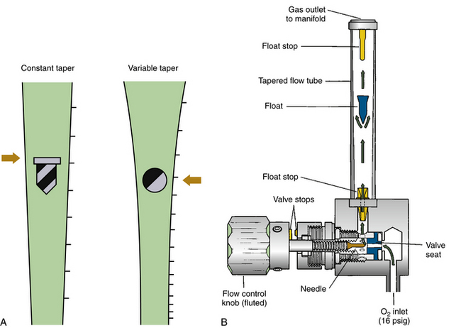
FIGURE 2-29 A, Constant- and variable-taper design tube flowmeters. B, Schematic section of an oxygen flowmeter and flow control valve. Designs may use a ball or an elongated float, as shown. Note that the flow control knob for oxygen is fluted (touch coded) to distinguish it from the other knobs, which are knurled. Minimum oxygen flow is achieved by valve stops in this GE Healthcare Datex-Ohmeda flow control system. (B, From Bowie E, Huffman LM: The anesthesia machine: essentials for understanding. Madison, WI, 1985, GE Datex-Ohmeda.)
At low flow rates, gas flow is essentially laminar, and Poiseuille’s law applies.17 Thus,

where π is the constant 3.142, P is the pressure difference across the bobbin, r is the radius of the tube, η is the viscosity of the gas, and L is the length of the bobbin or float. When flows are greater and the orifice is larger, turbulent flow occurs, in which case:

Flowmeters use a physical property of the gas to measure flow. In the case of low flows, when flow is laminar, the property used is the viscosity of the gas. At high flows, when flow is turbulent or orificial, gas density is used to measure flow.
Rotameters are precision instruments. Flow tubes are manufactured for specific gases, calibrated with a unique float, and are meant to be used within a certain range of temperatures and pressures. Whether the flow indicator float is a ball or a bobbin, flow on the calibrated scale should be read at the highest and widest portion of the float. Flowmeters are not interchangeable among gases. If a gas is passed through a rotameter for which it has not been calibrated, the flows shown are likely inaccurate. Theoretical exceptions to this are as follows. At low flows, flow rates of gases with similar viscosities, such as oxygen and helium, are read identically at 202 and 194 micropoise (μP), respectively; at high flows, gases of similar density—such as nitrous oxide and carbon dioxide, both of which have an atomic mass of 44—are read identically. Again, flowmeters are not interchangeable among medical gases, and modern machines are manufactured so that they cannot be interchanged.
The gas flow to the rotameter tube is controlled by a touch- and color-coded knob, which is linked to a needle valve (see Fig. 2-29). In the United States, the oxygen control knob is green, as is everything related to oxygen; it is also fluted and larger in diameter than the other gas flow control knobs.1 The nitrous oxide control knob is smaller, blue, and ridged or knurled, but not fluted like the oxygen knob (Fig. 2-30).
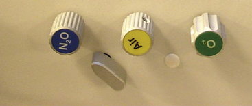
FIGURE 2-30 Gas flow control knobs. Oxygen is on the right and is fluted (touch coded). The second gas in this machine, air or nitrous oxide, must be selected by the switch. Note the absence of any guard device to prevent unintended changes in knob position. The flow control knobs for nitrous oxide and air are smaller than those for oxygen and are knurled.
Anesthesia machine manufacturers offer the option of oxygen flow that cannot be completely discontinued when the machine’s main ON/OFF switch is turned on—that is, when the machine is capable of delivering an anesthetic. This is because either a mechanical valve stop ensures a minimum oxygen flow of 200 to 300 mL/min past the partially open needle valve (see Fig. 2-29, right), or a gas flow resistor permits a similar flow of 200 to 300 mL/min to bypass a completely closed oxygen flow control needle valve.
The workstation standard requires that each flowmeter assembly be clearly and permanently marked with the appropriate color, unit of measure, and the name or chemical symbol of the gas it measures. The manufacturer should ensure that the flowmeters and tubes are not interchangeable among the different gases or between the low-flow (0 to 1 L/min) and high-flow (1 to 10 L/min) rotameter tubes for each gas. Flowmeters may also be pin indexed to eliminate the possibility of installing a flowmeter intended for a different gas.
Flowmeter tubes are fragile and are therefore protected on the machine by a plastic window. Individual flow control knobs may also be surrounded by a shield to prevent accidental alterations of the settings (Fig. 2-31). To obtain a true reading of flow, the rotameter tubes must be kept vertical to prevent the ball or bobbin from touching the sides of the glass tube. The flow should be read at the middle of the ball or at the top of the bobbin (see Fig. 2-29). The ball or bobbin is more likely to stick at low flows and where the tube is narrowest. Electrostatic charges and dirt may also interfere with the bobbin’s free movement; in this respect, a ball is superior to a bobbin because a ball is less likely to stick.
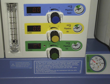
FIGURE 2-31 Front view of a Dräger Fabius GS workstation (Dräger Medical, Telford, PA) showing a vertical arrangement of the flow control knobs. The knobs are less susceptible to accidental changes in flow by the protective half-sleeves on either side of each knob (compare with Fig. 2-30).
Flowmeters are individually calibrated by the manufacturer against a master flowmeter for each gas. In clinical practice, flowmeter calibration is most easily checked by setting gas flows to produce desired nitrous oxide–oxygen concentrations and using a gas analyzer to check the composition of the gas mixture emerging from the machine’s CGO.
The positioning of the oxygen flowmeter in the bank of several gas flowmeters is important. The anesthesia workstation standard requires that the oxygen flowmeter be placed on the right side of the flowmeter group when the workstation is viewed from the front. It is also the most downstream flowmeter, closest to the CGO, to make hypoxia less likely in the event of a leak in one of the other flowmeters. Thus, if the oxygen flowmeter is placed upstream of a leaking nitrous oxide flow tube, oxygen would be lost through the leak and an excess of nitrous oxide would flow to the CGO.25 Although these considerations were important in the past,26 they may be less so now because the use of an oxygen analyzer in the inspiratory limb of the breathing system has become the standard of care.
Oxygen Ratio Monitoring and Proportioning Systems
A major consideration in the design of contemporary anesthesia machines is the prevention of delivery of a hypoxic gas mixture to the patient. The fail-safe system described above only interrupts, or proportionately reduces and ultimately interrupts, the supply of nitrous oxide and other gases to their flowmeters if the oxygen supply pressure to the machine decreases. It does not prevent delivery of a hypoxic mixture to the CGO.
In contemporary anesthesia machines, oxygen and nitrous oxide flow controls are physically interlinked either mechanically (Datex-Ohmeda machines) or mechanically and pneumatically (Dräger machines) so that a fresh gas mixture containing at least 25% oxygen is created at the level of the rotameters when nitrous oxide and oxygen are being delivered.4,6 In other contemporary workstations, proportioning is achieved by electronically controlled valves.
Datex-Ohmeda anesthesia machines use the Link-25 proportion-limiting control system to ensure an adequate percentage of oxygen in the gas mixture. In this system, the sizes of the openings of the oxygen and nitrous oxide flow control needle valves are proportioned and the supply pressures of these gases to their flow control valves are precisely regulated by second-stage (low-pressure) regulators. In addition, a gear (sprocket) with 14 teeth is integral with the nitrous oxide flow control spindle, and a sprocket with 29 teeth can rotate on a threaded oxygen flow control valve spindle, like a nut on a bolt (Fig. 2-32). The two sprockets are connected by a precision stainless-steel linked chain. Because of the 14:29 ratio of gear teeth, for every 2.07 revolutions of the nitrous oxide flow control spindle, an oxygen flow control, set to the lowest oxygen flow, rotates once. Because the sprocket on the oxygen flow control spindle is thread mounted so that it can rotate on the oxygen control valve spindle, oxygen flow can be increased independently of the flow of nitrous oxide. However, regardless of the oxygen flow set, if the flow of nitrous oxide is sufficiently increased, the chain will cause the oxygen sprocket to rotate and move outward toward the oxygen flow control knob. Eventually, a tab on the oxygen sprocket engages with a tab on the oxygen flow control knob, causing it to rotate in a counterclockwise manner, opening the oxygen needle valve and thereby causing the oxygen flow to increase. If nitrous oxide flow is decreased, the oxygen flow remains at the increased setting unless it is manually decreased. The proportioning of nitrous oxide to oxygen (75% to 25%) is completed because the nitrous oxide flow control valve is supplied from a second-stage gas regulator that reduces nitrous oxide pressure to a nominal 26 psig, adjusted as previously described, before it reaches the flow control valve. The oxygen flow control valve is supplied at a pressure of 14 psig from a second-stage oxygen regulator (Figs. 2-4 and 2-33). The Link-25 system permits the nitrous oxide and oxygen flow control valves to be set independently of one another, but when a setting of nitrous oxide concentration more than 75% is attempted, the oxygen flow is automatically increased to maintain at least 25% oxygen in the resulting mixture. This system thus increases the minimum flow of oxygen according to the nitrous oxide flow setting by further opening the oxygen needle control valve.4
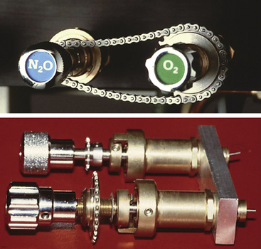
FIGURE 2-32 Datex-Ohmeda Link-25 Proportion Limiting System (GE Healthcare, Waukesha, WI). Top: Front view of flow control knobs, sprockets (N2O, 14 teeth; O2, 29 teeth), and stainless-steel link chain. Bottom: Side view shows N2O sprocket fixed on the spindle, whereas the O2 sprocket can move on the threaded O2 spindle, like a nut turning on a bolt.
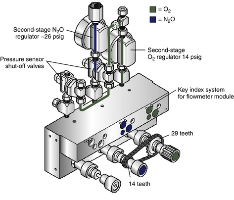
FIGURE 2-33 Schematic of Datex-Ohmeda Link-25 Proportion Limiting System (GE Healthcare, Waukesha, WI). A second-stage regulator for both O2 and N2O ensures that their flow control needle valves have a constant input pressure. Because Flow = Pressure/Resistance, in this system pressure is constant and resistance is adjusted via the needle valve orifices to maintain flow proportionality.
The Link-25 system interconnects only the nitrous oxide and oxygen flow control valves. If the anesthesia machine has flow controls for other gases, such as pure helium or air (see Figs. 2-27 and 2-28), a gas mixture containing less than 25% oxygen could be set at the level of the flowmeters. This potential hazard is addressed on more modern machines by supplying helium in tanks that contain a mixture of helium and oxygen (heliox) in a 75:25 ratio.
Older models of Narkomed machines use the oxygen ratio monitor controller (ORMC; Fig. 2-34) to limit the flow of nitrous oxide according to the oxygen flow, which creates a mixture of at least 25% oxygen at the flowmeter level when these two gases are being used.6,27 Newer models use the sensitive oxygen ratio controller (S-ORC) proportioning system. In principle, both ORMC and S-ORC work similarly. At oxygen flow rates of less than 1 L/min, concentrations of oxygen greater than 25% are delivered.
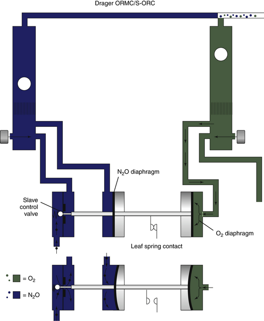
FIGURE 2-34 Dräger Medical oxygen ratio monitor controller (ORMC) and sensitive oxygen ratio controller (S-ORC) principles. In this system, resistance is kept constant by fixed resistors just downstream of each needle valve, and flow of N2O is kept proportioned by controlling pressure upstream of the N2O needle valve. (From Schreiber PJ: Anesthesia systems. Telford, PA, 1985, North American Dräger.)
The ORMC and S-ORC function much the same: as oxygen flows past the flow control needle valve and up the rotameter tube, it encounters a resistor that creates a backpressure, which is applied to the oxygen diaphragm (see Fig. 2-34); as nitrous oxide flows past its flow control valve and up into the rotameter tube, it also encounters a resistor that causes a backpressure on the nitrous oxide diaphragm. The two diaphragms are linked by a connecting shaft, whose ultimate position depends on the relative backpressures, and therefore flows, of nitrous oxide and oxygen. One end of the connecting shaft controls the orifice of a slave valve, which in turn controls the supply pressure of nitrous oxide to its flow control valve. When the oxygen flow is high, the shaft moves to the left and opens the slave control valve. Conversely, if the flow of nitrous oxide is increased excessively, the shaft moves to the right, closing the slave valve orifice and limiting the supply pressure, and thereby the flow, of nitrous oxide to its flow control valve.6
The Dräger ORMC and S-ORC differ from the Datex-Ohmeda Link-25 Proportioning Limiting System in a number of ways. First, the ORMC and S-ORC do not use second-stage oxygen and nitrous oxide regulators. Second, the ORMC and S-ORC limit the flow of nitrous oxide according to the flow of oxygen, whereas the Link-25 system increases the flow of oxygen as the nitrous oxide flow is increased. In the Link-25 system, once the oxygen flow has been increased via the link chain and gears, the oxygen flow remains at the increased setting even if the nitrous oxide flow is deliberately decreased. With the ORMC and S-ORC systems, if the system is acting to decrease the flow of nitrous oxide because the user has decreased the oxygen flow, when the flow of oxygen is increased again, the nitrous oxide flow will increase to its original setting. Third, like the Link-25 system, the ORMC and S-ORC function only between nitrous oxide and oxygen and there is no interlinking of oxygen with other gases, such as air or helium, that might be delivered by the machine. Thus, when a third or fourth gas is in use, the proportioning systems afford no protection against a hypoxic mixture at the CGO. Although of elegant design, the ORMC, S-ORC, and Link-25 systems are subject to mechanical and/or pneumatic failure (see Chapter 30) and should be tested according to the manufacturer’s instructions during the preuse machine checkout.28 Fourth, even if the systems are functioning correctly, they ensure delivery of no less than 25% oxygen at the flowmeter level. An oxygen leak downstream of the flowmeters, or the addition of high concentrations of a potent volatile inhaled anesthetic (e.g., 18% desflurane) also downstream of the proportioning systems, could result in a hypoxic mixture (i.e., <21% oxygen) being delivered from the machine CGO. An oxygen analyzer in the patient circuit is therefore essential if a potentially hypoxic mixture is to be detected and thereby prevented.
Vaporizer Manifolds
After individual gas flows have been measured by their respective rotameters, a mixture of the gases is created in a manifold downstream of the flowmeters. From here the gas mixture flows to the vaporizer manifold, where concentration-calibrated vaporizers are mounted on the machine. In older model Narkomed machines, the Dräger Vapor 19.1 vaporizers are permanently mounted and are not intended to be removed by the user. These vaporizers are mounted in series; that is, fresh gas flows through each vaporizer, albeit via a bypass channel, on its way to the CGO. An interlock device ensures that only one vaporizer can be turned on at any one time.
Contemporary anesthesia machines are designed so that the vaporizers are easily removable by the user. These vaporizer manifolds are designed such that no gas from the flowmeters enters any part of a vaporizer that is turned off, not even the vaporizer’s bypass channel. When a vaporizer is turned on, fresh gas enters only that vaporizer. This is important to understand when it comes to checking the machine’s low-pressure system. To check a vaporizer for leaks, it must be turned on to become connected to the low-pressure system of the machine. (Vaporizer manifolds are discussed in more detail in Chapter 3.)
Some departments maintain an anesthesia machine on which no vaporizers have been mounted; this makes an available “clean machine” for use with patients susceptible to malignant hyperthermia. In this case the gas mixture created at the flowmeter manifold is conducted directly to the CGO.
Common Gas Outlets and Outlet Check Valves
The fresh gas mixture produced by the settings of the flowmeters for oxygen, nitrous oxide, and/or other gases and vapor from one concentration-calibrated vaporizer exit the machine via the CGO. Some Datex-Ohmeda machines—such as the Modulus I, Modulus II, and Excel models—have an outlet check valve situated between the vaporizers and the CGO (Fig. 2-35) and a pressure relief valve (see Fig. 2-4). The pressure relief valve, as its name suggests, prevents the buildup of excessive pressures upstream of the outlet check valve. In some Datex-Ohmeda machines (Excel, Modulus I with Selectatec switch), the pressure relief valve is located downstream of the outlet check valve. In all machines, these components are located upstream from where the oxygen flush flow would join to pass to the CGO.
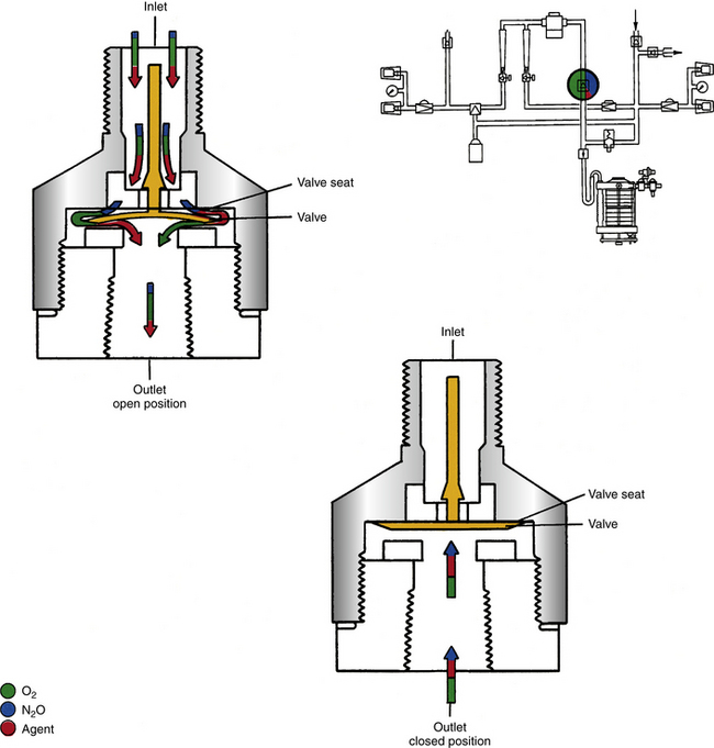
FIGURE 2-35 Machine outlet check valve located between the vaporizer and the common gas outlet. This valve is present on Datex-Ohmeda Modulus I, Modulus II, and Excel machines but not on Modulus II Plus or Modulus CD or on Dräger Medical Narkomed (Telford, PA) machines. The valve is designed to permit gas flow from the vaporizers to the common gas outlet and to prevent reverse gas flow, which might cause a pumping effect on the vaporizer. Increased pressure at the common gas outlet causes the valve to close. (From Bowie E, Huffman LM: The anesthesia machine: essentials for understanding. Madison, WI, 1985, GE Datex-Ohmeda.)
The use or nonuse of an outlet check valve varies among the various models of anesthesia machine. The pressure relief mechanism and its location with respect to an outlet check valve, if present, also vary. The reader is encouraged to review the schematic of machines in use to understand the configuration of its system.
The purpose of the outlet check valve is to prevent reverse gas flow, a situation that could permit fresh gas to reenter the vaporizer (“pumping effect”) if the vaporizer did not have its own outlet check valve or specialized design. This effect, if not prevented, can cause increased concentrations of anesthetic agent output (see Chapter 3).
Narkomed 2A, 2B, 2C, 3, and 4 machines are designed so that an outlet check valve is not required. The pumping effect is eliminated by the special design of the vaporizers. The Modulus II Plus and Modulus CD machines are equipped with Datex-Ohmeda TEC 4 or TEC 5 vaporizers, which incorporate a baffle system and a specially designed manifold to prevent the pumping effect; this makes an outlet check valve unnecessary. Nevertheless, the Modulus II Plus and Modulus CD machines do have a pressure relief valve upstream of the CGO.29
Narkomed machines do not have a separate pressure relief valve. If required, pressure relief occurs when the pressure exceeds 18 psig through the specially designed vaporizers. The presence or absence of an outlet check valve and pressure-relief valve is of some significance when it comes to leak testing the low-pressure system of the anesthesia machine; it also affects the performance of a transtracheal jet ventilating system connected to the CGO.
Transtracheal jet ventilation systems are sometimes needed by anesthesiologists for use in an emergency. Ideally, a purpose-designed Sanders-type transtracheal jet ventilation system is available in every anesthetizing location and certainly in the difficult airway cart. This system is connected via a pressure-reducing valve and toggle switch to a separate 50-psig oxygen source.18 However, some anesthesia care providers have described “homemade” systems designed to be connected to the machine CGO via a 15-mm connector, and ventilation is achieved by intermittent depression of the oxygen flush button.30-32 The driving pressure of such systems is limited by the threshold-opening pressure of the pressure-relief mechanism, if present (see Fig. 2-4). In the case of Modulus II Plus or Modulus CD machines, the pressure relief valve opens at 2.2 to 2.9 psig. In the case of Narkomed machines equipped with vaporizers, it opens at 18 psig. In the case of Modulus I and Modulus II machines (outlet check valve present) and Narkomed machines without vaporizers (no pressure relief system), the driving pressure available at the CGO is 45 to 55 psig, depending on whether the tank or pipeline oxygen supply to the machine is in use (see Fig. 2-4). The “cracking” pressure of the relief mechanisms—that is, the pressure at which the relief valve first begins to open—provides some guide to the potential driving pressure available for the transtracheal ventilating system. In practice, pressures a little higher than the cracking pressure are generated because of both the flow restriction offered by the relief valve and that offered by the ventilating system. It should be noted, however, that anesthesia machine oxygen flush systems were not designed or intended by the manufacturers to be used for transtracheal jet ventilation. For these reasons anesthesia machine oxygen flush systems should not be used for this purpose.
The anesthesia workstation standard requires anesthesia machines to have only one CGO. When that CGO is connected to the breathing system by a fresh gas supply hose, the usual arrangement in most ORs, the CGO must be provided with a manufacturer-specific retaining device.1 The purpose of the retaining device is to help prevent disconnection or misconnections between the machine’s CGO and the patient circuit. Thus a disconnection here would result in failure to deliver the intended gas mixture, with possible entrainment of room air if a hanging bellows design of ventilator or a piston ventilator were used; this could result in a hypoxic mixture in the circuit in addition to patient awareness as a result of failure of delivery of inhaled anesthetic. The machine manufacturers use their own proprietary retaining devices (Fig. 2-36). The workstation standard requires that the CGO have a 15-mm female fitting or a coaxial fitting with a 15-mm internal diameter and 22-mm external diameter. It must not incorporate a 19-, 23-, or 30-mm conical fitting because these are specific for other parts of the delivery system, specifically the patient circuit and the waste gas scavenging system (see Chapter 16).
FIGURE 2-36 Left, Spring-loaded bayonet fitting retaining device at the common gas outlet (CGO) of a Datex-Ohmeda (GE Healthcare, Waukesha, WI) anesthesia machine. Right, CGO (top) and retaining device (bottom) on a GE ADU workstation. These devices are designed to prevent accidental disconnection of the hose that connects the CGO to the patient breathing circuit.
Concerns about disconnections at the CGO have led to some machine and workstation designs in which the outlet is not accessible to the user. Examples include the Datex-Ohmeda Aestiva/5; the Datex-Ohmeda Aespire, Avance, and Aisys Carestations that use the Advanced Breathing System; and the Dräger Apollo workstation.
The Aestiva/5 machine has an auxiliary CGO that, when selected, diverts the fresh gas flow to this outlet, switching out the circle system (Fig. 2-37). This allows use of a rebreathing system. The auxiliary CGO must be selected to perform the machine’s low-pressure system leak check. Once the leak check is complete, the user must remember to switch out the auxiliary CGO to use the circle system.
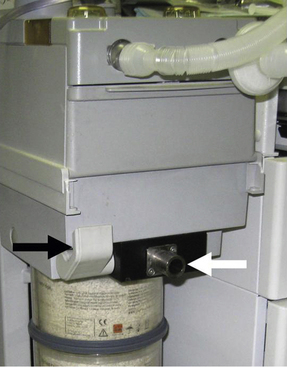
FIGURE 2-37 Auxiliary common gas outlet (white arrow) on a Datex-Ohmeda Aestiva/5 machine (GE Healthcare, Waukesha, WI). This outlet is enabled and the connection to the circle system is disabled by pressing down the lever (black arrow) to the left of the outlet. This outlet is used to perform the low-pressure system leak check or to connect a noncircle system.
An auxiliary CGO similar to that of the Aestiva/5 is an option on GE machines that use the Advanced Breathing System. In one case report, a massive leak developed in an Aisys Carestation during a neurosurgical procedure. Being unable to correct the situation, the authors reported completing the anesthetic by switching to a Bain circuit connected to the alternate CGO.33
The Datex-Ohmeda ADU and the Dräger Fabius GS have accessible CGOs, whereas the Dräger Apollo workstation does not and therefore can be used only with a circle breathing system.
Anesthesia Machine Low-Pressure System Checkouts
The anesthesia delivery system should be checked each day before the first procedure and when any change has been made to the system. Such changes include replacement of the ventilator bellows or anesthesia circuit and movement of the anesthesia machine in the operating room; moving the machine may cause kinking or compression of the tubing, which in turn may produce interference with gas delivery, ventilator function, or waste gas scavenging. Thus, in addition to a complete check at the start of each day, a shortened check of the delivery system should precede each procedure.
In August 1986, the U.S. Food and Drug Administration (FDA) published its Anesthesia Apparatus Checkout Recommendations, which included 24 steps.34 A study subsequently reported that anesthesia practitioners did not appropriately apply this checkout protocol.34 In 1993, the FDA published a revised checkout that had only 14 steps (see Table 32-1 in Chapter 32).11 One of the most important steps in these checks is that of checking the machine’s low-pressure system for leaks.
Testing for Leaks in the Anesthesia Machine and Breathing System
Many traditional anesthesia machines, for which the FDA 1986 and 1993 checks were designed, remain in service around the world. The following discussion of checking the low-pressure system for leaks is therefore still relevant. In particular, an appreciation of the principles of the low-pressure system check and its relation to the presence or absence of an outlet check valve is essential. Application of the incorrect check could result in a large leak being missed.
Item 16 in the FDA 1986 checklist described what should be done before each patient procedure. This check evaluates the components of the delivery system downstream of the flowmeters (i.e., the low-pressure system) and should detect gross leaks that may be due to cracked rotameter tubes, leaking gaskets and vaporizers, and leaks in the anesthesia circuit. In this generic test, the APL valve, or “pop-off valve,” is closed, and the patient circuit is occluded at the patient end. The system is then filled via the oxygen flush until the reservoir bag is just full but with negligible pressure in the system. Oxygen flow is set to 5 L/min and then slowly decreased until pressure no longer rises above approximately 20 cm H2O (Fig. 2-38). This set flow is said to approximate the total rate of gas leak, which should be no greater than a few hundred milliliters per minute. The reservoir bag should then be squeezed to a pressure of about 50 cm H2O to verify that the system is gas tight. If the leak is large enough, the circuit pressure may fall to zero (Fig. 2-39).
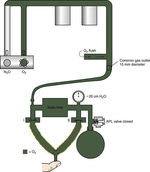
FIGURE 2-38 The U.S. Food and Drug Administration 1986 generic leak check procedure of low-pressure system in a machine with no outlet check valve. In the absence of a leak, pressure is maintained at 20 cm H2O. APL, adjustable pressure limiting. (From Eisenkraft JB: The anesthesia delivery system, part II. In Eisenkraft JB, editor: Progress in anesthesiology, vol 3. San Antonio, TX, 1989, Dannemiller Memorial Educational Foundation. Reproduced by permission.)
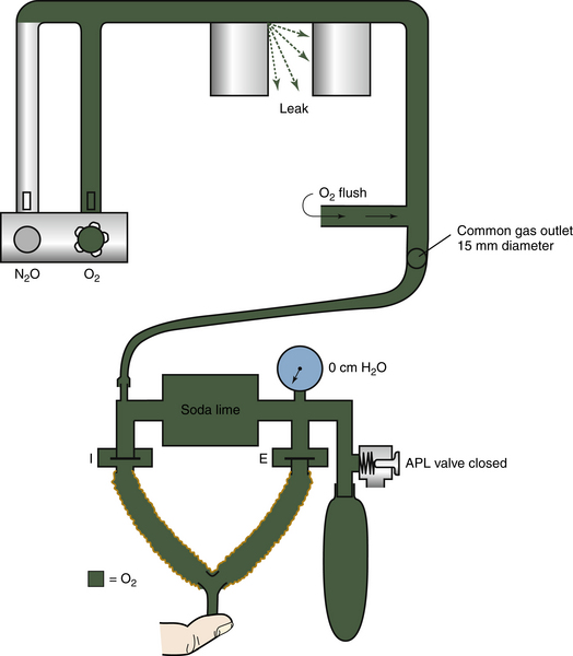
FIGURE 2-39 The U.S. Food and Drug Administration 1986 generic leak check procedure in a machine with no outlet check valve. A leak at the vaporizer mount results in failure of the system to hold pressure, which in this case has fallen to zero. Such a leak would not be detectable if an outlet check valve were present because pressure applied at the common gas outlet would not be transmitted into the vaporizer manifold. APL, adjustable pressure limiting. (From Eisenkraft JB: The anesthesia delivery system, part II. In Eisenkraft JB, editor:Progress in anesthesiology, vol 3. San Antonio, TX, 1989, Dannemiller Memorial Educational Foundation. Reproduced by permission.)
The advantages of this test routine are that it can be performed quickly and that it checks the patient circuit as well as the low-pressure components of the machine in models that do not have an outlet check valve. Disadvantages of this process are that it is relatively insensitive to small leaks, and in machines that have an outlet check valve—such as the Modulus I, Modulus II, and Excel models—only the patient circuit downstream of the outlet check valve is tested for leaks.
The generic check is insensitive because it depends on volume. Thus, in this test, a large volume of gas—in effect, that contained in the circuit tubing, absorber, and reservoir bag—is compressed. The circuit pressure gauge is then observed for any changes. The term compliance expresses the relationship between volume and pressure and is defined as change in volume per unit change in pressure. Because of the large volume of gas compressed and the high compliance of the distensible reservoir bag, relatively large changes in volume (i.e., leaks) may exist with minimal changes in pressure. The anesthesiologist performing the check is looking for a pressure decrease as an indicator of gas leakage; however, relatively large leaks may go undetected by this test.
The second limitation of the FDA 1986 generic check is related to the presence or absence of an outlet check valve. Application of the generic leak check in this situation tests only for leaks in components downstream of the outlet check valve (Fig. 2-40).
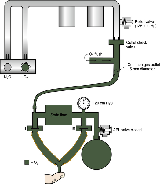
FIGURE 2-40 Application of the U.S. Food and Drug Administration 1986 generic leak check procedure to a system with an outlet check valve. In this case, application of a positive backpressure of 20 cm of water causes the check valve to close so that only those components downstream of the outlet check valve are leak tested. APL, adjustable pressure limiting. (From Eisenkraft JB: The anesthesia delivery system, part II. In Eisenkraft JB, editor: Progress in anesthesiology, vol 3. San Antonio, TX, 1989, Dannemiller Memorial Educational Foundation. Reproduced by permission.)
The limitations of the FDA 1986 generic leak checkout make it obvious that specialized leak checks of the low-pressure system must be used, and the operator’s manual for each machine should be consulted for details. Tests described for the Narkomed and Datex-Ohmeda machines are briefly reviewed in the following sections to illustrate the differences in system design, function, and check.
Narkomed Machines: No Outlet Check Valve
Dräger Medical recommends the following test procedure for checking the anesthesia breathing system and fresh gas delivery system.35 In this test, all gas flow control (flowmeter) valves are closed, and the machine system main power switch is turned to STANDBY or OFF. In this position, no gas should flow to the flowmeters or from the CGO, and all vaporizer concentration dials are set to ZERO concentration. The inspiratory and expiratory valves are short circuited with 22-mm diameter circuit hose (Fig. 2-41). The shortest possible length of hose should be used to minimize contained gas volume. The MANUAL/AUTOMATIC selector valve is set to the MANUAL (bag) position. The APL (pop-off) valve is closed by turning it fully clockwise. The reservoir bag is removed, and the test terminal is attached to the bag mount (see Fig. 2-41). A sphygmomanometer squeeze bulb is connected to the hose barb on the test terminal. It should now be apparent that the total volume of the circuit components has been drastically reduced by the removal of the circle system tubing: a circle with each limb 152 cm (5 feet) in length has a volume of about 1200 mL, and the reservoir bag has a volume of 3 L. The sphygmomanometer bulb is squeezed by hand until the pressure shown at the breathing system pressure gauge indicates a pressure higher than 50 cm H2O. The gauge is then observed for a decrease in pressure. Per manufacturer specifications, the pressure should not decrease to less than 30 cm H2O over a 30-second observation period.14 Because the volume of gas being compressed in this test is minimal (i.e., circuit compliance has been significantly decreased), small gas leaks will result in a decrease in pressure that is observable on the circuit pressure gauge.
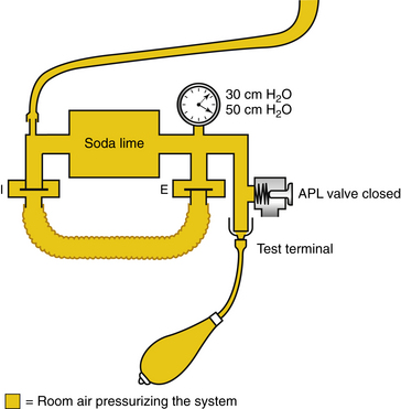
FIGURE 2-41 Narkomed positive-pressure leak check (Dräger Medical, Telford, PA). The system is pressurized to 50 cm H2O and the pressure gauge observed for 30 seconds. To pass this leak check, the pressure must not fall below 30 cm H2O within 30 seconds. APL, adjustable pressure limiting. (From Eisenkraft JB: The anesthesia delivery system, part II. In Progress in anesthesiology, vol 3. San Antonio, TX, 1989, Dannemiller Memorial Educational Foundation. Reproduced by permission.)
The positive-pressure leak check should be repeated sequentially with each vaporizer turned on and set at any concentration greater than 0.4%. This checks for leaks in individual vaporizers (e.g., filler caps, selector switches, and vaporizer mounts).
The test specifications given in this section apply to an anesthesia breathing system without accessories, such as the volumeter, sidestream gas analyzer, and other adapters. Test limits will be exceeded if accessory items are included in the test. The specific suppliers of the accessory items should be contacted for leak specifications of their devices.
Leaks in the patient circuit components can be distinguished from leaks in the low-pressure part of the Narkomed machine. If a leak has been identified with the combined circuit machine positive-pressure leak check, as described above, the sphygmomanometer bulb can be connected to the machine’s CGO with a 15-mm (tracheal tube) connector and to a pressure gauge with a three-way stopcock. With this arrangement, only the anesthesia machine, as opposed to machine and circuit in the previous test, is pressurized to 50 cm H2O. A decrease in pressure indicates a leak within the machine upstream of the CGO.
Datex-Ohmeda Machines with an Outlet Check Valve
In some Datex-Ohmeda machines, the presence of an outlet check valve complicates positive-pressure testing of the machine’s low-pressure system (see Fig. 2-40). Application of positive pressure downstream of the valve causes it to close, so only components downstream of the CGO are checked for leaks. Positive-pressure ventilation and opening of the oxygen flush valve cause the check valve to close (see Figs. 2-4 and 2-41). For this reason, GE Healthcare developed a negative pressure leak test to be performed with a special suction bulb device that is supplied with machines having this valve (Fig. 2-42).
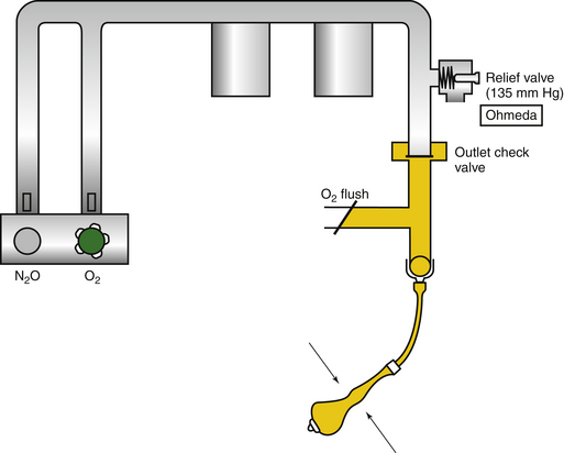
FIGURE 2-42 Datex-Ohmeda (GE Healthcare, Waukesha, WI) negative-pressure leak check procedure in a machine with an outlet check valve. (From Eisenkraft JB: The anesthesia delivery system, part II. In Progress in anesthesiology, vol 3. San Antonio, TX, 1989, Dannemiller Memorial Educational Foundation. Reproduced by permission.)
First, the adequacy of the leak testing device should be checked by sealing the inlet connector of the bulb and squeezing the bulb until it is collapsed. The bulb is then released, and the time taken to reinflate it is observed. If reinflation occurs in less than 60 seconds, the device should be replaced.29 The device is checked periodically, at times of machine servicing, to ensure that the vacuum produced by the evacuated bulb is at least −65 mm Hg.
The device is then used to check the machine.23 First, the anesthesia machine’s system master switch and all vaporizers are turned off so that no gases are flowing in the low-pressure parts of the machine. Each gas supply is then opened by turning on the backup cylinder valves or by connecting the pipeline supply. The flow control valves (rotameters) are turned fully to the OPEN position. Thus with the master switch turned off and the flowmeters open, no gas is flowing, but the entire system is accessible for testing. The testing bulb is attached to the machine’s CGO via a 15-mm connector and is repeatedly squeezed and released until it remains collapsed. If the bulb reinflates within 30 seconds (Fig. 2-43), a leak of as little as 30 mL/min is present. The test procedure is repeated with each vaporizer turned to the ON position to look for leaks in the individual vaporizers. If the source is not easily correctable, the machine should be withdrawn from service. When the leak tests are complete, the negative-pressure bulb is removed from the CGO. Because the leak check described is conducted with all the flow-control valves open, components up to and including the machine’s main ON/OFF control switch are also tested for leaks.
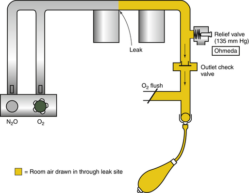
FIGURE 2-43 Datex-Ohmeda (GE Healthcare, Waukesha, WI) negative-pressure leak check procedure. When there is a leak in the machine, the evacuated bulb reinflates. (From Eisenkraft JB: The anesthesia delivery system, part II. In Progress in anesthesiology, vol 3. San Antonio, TX, 1989, Dannemiller Memorial Educational Foundation. Reproduced by permission.)
The negative pressure leak check described for Datex-Ohmeda machines results in the outlet check valve being held open by the −65 mm Hg vacuum (see Figs. 2-42 and 2-43) and air or gas being sucked into the system through any leaks. If such leaks were present while the machine was in service, anesthesia gases would escape from the system. If the anesthesia machine is found to have a leak, it should be withdrawn from use until an authorized agent has repaired the leak, rechecked the system, and certified that the machine is fit to be put back into clinical service.
Datex-Ohmeda Machines Without an Outlet Check Valve
GE Healthcare recommends the negative leak test procedure described above to check for leaks in Modulus II Plus and Modulus CD machines, which have no outlet check valves.36 Although the bulb could, in principle, be used to check for leaks in a Narkomed machine, Draeger Medical does not provide specifications for the application of such a leak check device on their products. Item 5 of the FDA’s 1993 Anesthesia Apparatus Checkout Recommendations describes the use of a negative-pressure suction bulb to check a machine’s low-pressure system for leaks. They require that the bulb stay fully collapsed for at least 10 seconds. A study comparing tests for leak testing the low-pressure system reported that only the negative-pressure leak test detected all leaks and concluded that “adoption of the negative-pressure test as a universal [low-pressure system] leak test may prevent the risks associated with using the wrong test for the particular anesthesia machine.”37
These descriptions of the pneumatic system apply in principle to all anesthesia machines and workstations, but, as previously stated, many of the traditional mechanical components are being replaced by more modern devices, such as those described in the following paragraphs.
Datex-Ohmeda Aestiva/5
The Aestiva/5 is an example of a modern basic anesthesia machine (Fig. 2-44). Gauges on the front panel display the gas supply pressures, and a main ON/OFF switch enables electronic and pneumatic functions. Gas flows are controlled with the traditional needle valves and glass rotameter tubes. The majority of the vaporizers are mechanical Tec-type vaporizers. The CGO is not accessible to the user because the fresh gas flow is conducted directly into the absorber–ventilator–circle system unit. An auxiliary CGO can be selected to divert all fresh gas flow to this outlet. This allows use of noncircle breathing systems (e.g., Bain) and provides access to the machine’s low-pressure system for application of the negative-pressure leak check. With the exception of the ventilator controls, the system is essentially mechanical and pneumatic so that an anesthetic can be delivered in the absence of electrical power, although the unit does have a backup battery.
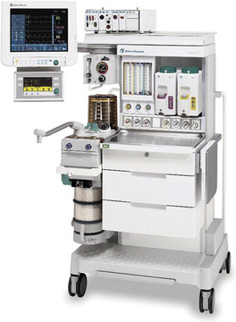
Datex-Ohmeda S5/ADU Workstation
The S5/ADU workstation represents the next step toward an all-electronic workstation (Fig. 2-45). Gas pressures are measured by conventional gauges, and gas flow is controlled by knobs and traditional needle valves. Gas flows, however, are measured electronically and are displayed on a color screen as virtual rotameters and as digital values. The workstation has an electronically controlled anesthetic vaporizer that uses agent-specific cartridges (see Chapter 3). Electronic measurement has several benefits:
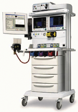
FIGURE 2-45 GE Healthcare (Waukesha, WI) ADU workstation. The next step in evolution: electronic flow sensing, virtual flowmeters, and an electronically controlled vaporizing system.
1. Accuracy is enhanced because there is no confusion over where to read the flow on a traditional rotameter float and the system is sensitive to very low flows.
2. Proportioning of N2O and O2 is performed by computer-controlled solenoid valves that ensure a minimum of 25% oxygen when nitrous oxide is used. Because the vaporizing system is also electronic (see below), it can decrease the flow of nitrous oxide to maintain 25% oxygen when high concentrations of desflurane are used (Fig. 2-46).
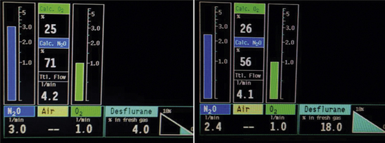
FIGURE 2-46 Electronic proportioning system in the GE Healthcare (Waukesha, WI) ADU. Left, Minimum 25% O2 with N2O and low concentration of desflurane. Right, When desflurane is increased to 18%, the proportioning system automatically decreases N2O flow to maintain minimum O2 concentration.
3. During volume ventilation, the flow measurements are used to ensure that changes in fresh gas flow, respiratory rate, and the inspiration/expiration ratio do not change the tidal volume from that set to be delivered. Thus, if fresh gas flow is increased, the computer immediately decreases the volume delivered from the ventilator bellows.
4. The electronic flow data and anesthesia vaporizer concentration data permit continuous monitoring of volatile anesthetic agent use. The data can also be downloaded to an anesthesia information management system.
5. The electronic display can be easily modified by software changes. This eliminates the need to manufacture different machines for different countries, such as to follow local convention for gas colors.
6. Troubleshooting a computerized system may be easier for service personnel. Repairs may require simple replacement of a module.
7. A partially automated and manually menu-driven check procedure is standard. During checkout the compliance of the breathing system is measured, and this information is used by the ventilator software so that the tidal volume set is delivered to the patient.
Disadvantages: Gas flow cannot be measured when electrical power is lost, but flows can still be controlled by flow control knobs and needle valve assemblies. For this reason, a rotameter flowmeter is available for installation at the CGO to measure the total fresh gas flow, albeit without the normal accuracy. To deliver 40% oxygen with nitrous oxide using the common gas flowmeter in the event of power loss, starting with all gas flows off, it is possible to dial up 2 L/min of oxygen and then nitrous oxide until the total flow is 5 L/min (Fig. 2-47). Loss of electrical power to the ADU workstation would result in failure of the gas analyzer, and therefore in oxygen monitoring, as well as an inability to deliver a potent inhaled anesthetic agent because of the electronic vaporizer. Therefore, if all electrical power were to be lost, the ADU workstation could still deliver N2O and O2 to the breathing circuit; ventilation would have to be spontaneous or manual, and intravenous agents would be required to replace the potent inhaled anesthetic.
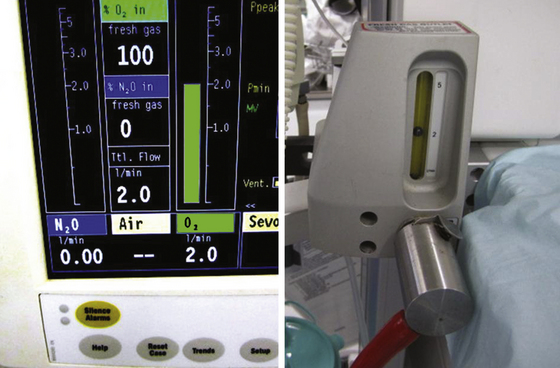
Other Features: The potent agent vaporizer concentration control dial is electronic, but contrary to electronic convention, an increase in concentration requires counterclockwise rotation of the dial; the dialed-in concentration is displayed on the screen. The CGO is accessible, and the workstation has a backup battery that will energize the anesthesia machine parts of the workstation, but not the physiologic monitors, for 45 to 90 minutes. An indicator on the screen shows the state of the battery charge when it is in use.
Contemporary Anesthesia Workstations
Aisys Carestation
The Aisys Carestation is an example of a fully computerized electronic workstation. When turned on, the workstation goes through an automated check that requires some menu-driven actions by the user. Gas supply pressures are measured electronically by pressure transducers and are displayed digitally on a screen. The supplied gases—O2, N2O, and air—pass to an electronically controlled gas mixer, where the desired flows and concentrations are created. The flow of each gas is determined by pressing a key to select the gas flow and then confirming by pressing the ComWheel. Alternatively, the concentration of oxygen in N2O or air and the total gas flow can be set (Fig. 2-48). The concentrations and individual gas flows are displayed as virtual flowmeters on a computer screen. The gas mixture then passes to an electronic vaporizer, where the electronically set agent concentration is added. Because no CGO is accessible on the basic model, the resulting fresh gas mixture is conducted to the circle breathing system.
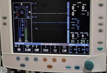
FIGURE 2-48 GE Healthcare (Waukesha, WI) Aisys Carestation showing virtual flowmeter display of N2O at 2.5 L/min and O2 at 2.5 L/min. This was achieved by setting a total flow of 5 L/min followed by the desired O2 concentration of 50%. Gas flows can also be controlled individually by selecting a different screen setup option.
The Aisys offers two types of CGO, the auxiliary common gas outlet (ACGO) or a switched common gas outlet (SCGO). The ACGO is a port on the front of the machine through which fresh gas exits when the ACGO is selected by an adjacent switch. This is similar to the ACGO on the Aestiva/5 described above (see Figs. 2-37 and 2-44). The ACGO allows use of a noncircle system and also provides a place for attaching a negative-pressure bulb for leak testing the low-pressure system, as described above. When selected from the Aisys start-up menu screen, the SCGO mode functionally converts the inspiratory port for the circle into a CGO. It does this by diverting fresh gas so that it bypasses the inspiratory unidirectional valve and emerges through the inspiratory flow sensor.
There are obvious major differences between the Aisys Carestation and the ADU. For example, gas flows are under full electronic control. Having pressed the key for the gas to be controlled, flow is adjusted by turning the com wheel to the desired concentration and then confirming. Adjustment is therefore a two-step process that is implemented only after being actively confirmed. Because this is an electronic control, by convention an increase in flow and agent concentration is by clockwise rotation of the com wheel. With the traditional needle valve flow control, flow is increased by counterclockwise rotation of the flow control knob. Similarly, with conventional vaporizer dials, concentration is increased by counterclockwise rotation of the dial.
Disadvantages: Power supply failure to the Aisys would result in the electronic gas mixer and vaporizer shutting down. To deal with this possibility, the machine has an alternate oxygen flowmeter (not to be confused with the auxiliary oxygen flowmeter) that is a basic mechanical needle valve and rotameter tube (Fig. 2-49). In the event of power loss, the workstation switches to the mechanical, alternate oxygen flow control system so that oxygen can continue to be delivered to the patient breathing system; the same would happen if the gas mixer were to fail. If the gas mixer fails but the electronic vaporizing system is working, potent inhaled agent can be added to the alternate oxygen flow. An ON/OFF switch for the alternate oxygen flowmeter can be used and tested if necessary.
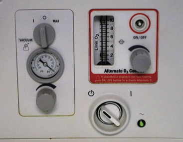
FIGURE 2-49 Alternate O2 control and rotameter flowmeter on the GE Healthcare (Waukesha, WI) Aisys Carestation for use in the event of electrical power supply failure, failure of the anesthesia screen display, or failure of the O2-N2O-air gas mixer module.
During startup, the Aisys goes through a 5-minute automated check that also requires some procedures to be performed by the user, although they can be bypassed in an emergency. The Aisys backup battery is specified to power the anesthesia machine components (vs. the physiologic monitors) for 40 minutes.
As previously mentioned, all anesthesia delivery systems are the same in principle, but the functions of some components have been affected by modern technology. This is illustrated in Figure 2-50, which shows the gas flow arrangements of the Aisys Carestation.
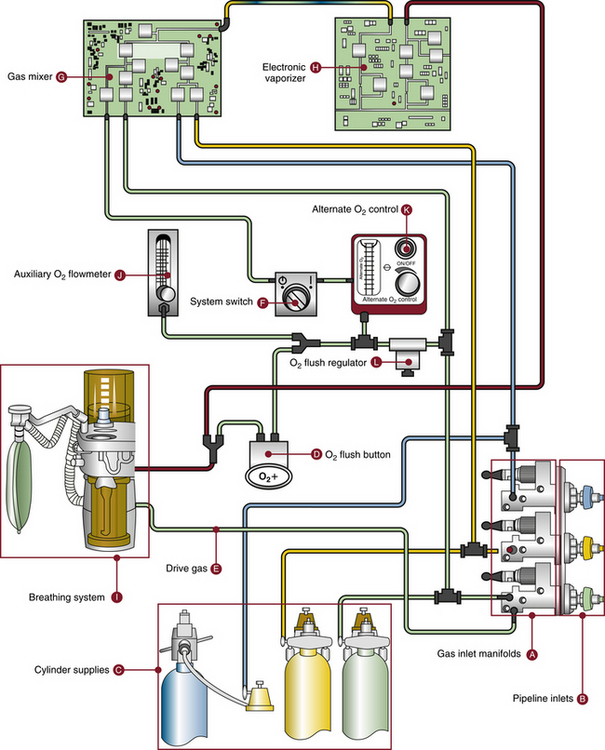
FIGURE 2-50 Gas flow schematic of Aisys Carestation (GE Healthcare, Waukesha, WI). It is essentially the same as the basic machine schematic in Figure 2-4. Electronic components have replaced many of the traditional ones. (From Explore the anesthesia machine: Aisys. Madison, WI, 2005, GE Healthcare.)
Dräger Fabius GS Premium
The Fabius GS Premium workstation is currently the basic model from Dräger Medical (Fig. 2-51). Conventional pressure gauges on the front of the workstation display the cylinder and pipeline gas supply pressures. Gas flow control is by conventional flow control knobs and needle valves that are arranged vertically rather than horizontally. Gas flow measurement is by flow sensors, rather than by traditional rotameters, and flows are displayed digitally to the left of the flow control knobs and as virtual flowmeter displays on the color screen. A rotameter located to the left of the digital flow readings (see Fig. 2-51) continuously measures the total fresh gas flow with an accuracy specified as ±15%. The majority of vaporizers are of the traditional, mechanical, variable-bypass design. With this workstation, in the event of electrical power loss, an inhaled anesthetic can be delivered because of the total gas flow rotameter and mechanical vaporizers. The fresh gas flow exits the machine via an accessible CGO to be conducted to the breathing system.
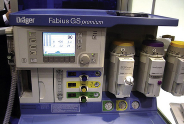
FIGURE 2-51 The Fabius GS Premium workstation (Dräger Medical, Telford, PA). Note needle valve gas flow controls arranged vertically and the electronic display of virtual flowmeters. A total fresh gas rotameter flowmeter permits flow measurement in the event the electronic flow display fails.
An auxiliary oxygen flowmeter is provided. Unlike the GE workstations, which have gas-driven bellows ventilators, the anesthesia ventilator in the Fabius GS is piston driven by an electric motor. The preuse check is not automated, and Dräger states that the checkout procedure pages in the operator’s instruction manual be “removed and copied to establish a daily record of machine checks.” The company also states that each function should be marked after successful completion of the machine checks.38 It is essential to perform all the steps of the manufacturer’s recommended check procedure because omission of any steps or failure to perform the check properly may result in a large internal gas leak going undetected.39
Apollo Workstation
The Dräger Medical Apollo workstation (Fig. 2-52) has an advanced design that incorporates many more electronic features than the Fabius GS. Before use, the workstation requires a manual, menu-driven check followed by an automated check (Figs. 2-53 and 2-54). Gas supply pressures are measured by pressure transducers and are displayed on the color screen. Individual gas flows are controlled by mechanical needle valves and conventional flow control knobs arranged horizontally. As in the Fabius GS Premium described above, gas flows are measured by flow sensors and are displayed digitally and as virtual flowmeters on the screen. A traditional rotameter displays the total fresh gas flow. The majority of the vaporizers are of the traditional, mechanical, variable-bypass design. In the event of electrical power loss with this workstation, an inhaled anesthetic can be delivered because of the total gas flow rotameter and mechanical vaporizers. The anesthesia ventilator uses a piston driven by an electric motor, and the CGO is not accessible to the user; fresh gas flows directly into the autoclavable compact breathing system.
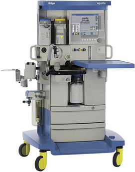
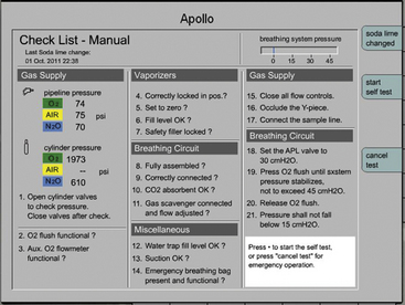
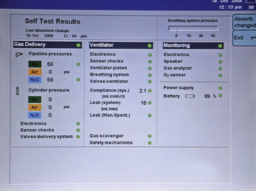
Anesthesia Machine Electrical Systems
Although basically pneumatic, all contemporary anesthesia machines also incorporate electrical systems and require connection to an electrical power supply. Turning the main switch clockwise to ON (Fig. 2-55) energizes the electrical systems of the machine and mechanically opens the flow of gases to the flowmeters, provided gas supply pressure is adequate, so that the machine is capable of delivering an anesthetic. The electrical system powers the alarms and monitors on the machine and also powers the ventilator control system. If the machine’s electrical system completely failed, the flow of gases to the flowmeters would continue uninterrupted as long as the machine’s main switch is ON. In the event that the AC power supply to the machine fails, a 12-volt battery serves as a backup system to provide power to the workstation’s monitors, alarms, ventilator controls, and motor, if so designed. When fully charged, the battery supply provides power for 30 to 45 minutes in most machines. However, a fully charged battery requires that the machine’s AC power cord be plugged into an energized electrical receptacle. A battery test indicator is provided on the machine to check for the status of the reserve power battery (see Fig. 2-54). The amount of time a workstation can function when the AC power fails can be extended by connecting the workstation and other essential devices, such as the computerized record-keeping system, into an uninterruptible power supply connected to a wall outlet so that its charge is maintained (Fig. 2-56). An uninterruptible power supply source is especially important in computerized workstations; if power is interrupted, the workstation computer may shut down and require a restart, which may take several minutes. This is also a consideration in the design of the workstation’s main ON/OFF switch because unintentionally turning off the workstation commits the user to a repeat start-up protocol. In an emergency, the workstation permits the user to bypass the automated check, but that action is logged into the memory.
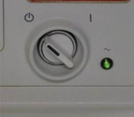
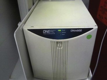
FIGURE 2-56 Uninterruptible power supply unit supplements the workstation backup battery by energizing monitors and automated anesthesia record-keeping systems.
Contemporary anesthesia machines are commonly equipped with a number of convenience receptacles or outlets to provide AC power to other monitors, such as the blood pressure monitor and pulse oximeter. These receptacles are energized via the machine’s main AC power cord and are protected by circuit breakers.
The presence of several electrical systems on the machine necessitates that each circuit be protected from overload. This is achieved by using circuit breakers, which vary in number according to the number of circuits present. In principle, however, one circuit breaker protects the machine’s main AC power supply, one or more protect the convenience receptacles, and one or more protect the low-voltage (12-volt) DC circuits. It is not uncommon for circuit breakers on the machine to be tripped, usually from overloading a convenience receptacle, such as by connecting an OR table power cord In this case, other convenience receptacles on the same circuit will have their power interrupted. The anesthesiologist should be familiar with the power supply capabilities of the receptacles, the power demands of any equipment connected to them, and the location (which is not always obvious) and function of the circuit breakers on the machine. The manufacturer’s manual should be consulted for details on specific models.
Anesthesia Machine Obsolescence and Preuse Checks
With the evolution of the anesthesia machine to the workstations of today, many safety features have been added. As a result, many older models of machine still in use may be considered outdated or even obsolete. The American Society of Anesthesiologists (ASA) Committee on Equipment and Facilities has developed guidelines for determining whether a machine is obsolete (see Chapter 30).40
The 1993 FDA checklist is not applicable to many newer workstations. Recognizing this, a subcommittee of the ASA Committee on Equipment and Facilities reviewed the 1993 recommendations in relation to newer workstations and published their findings in 2008 (summarized in Table 32-1 in Chapter 32).15 The report stated that “anesthesia delivery systems have evolved to the point that one preanesthesia checkout procedure (PAC) is not applicable to all the anesthesia delivery systems currently on the market. For these reasons, a new approach to the PAC has been developed. The goal was to apply guidelines applicable to all anesthesia delivery systems so that individual departments can develop a PAC that can be performed consistently and expeditiously.” The 2008 guidelines are intended to provide a template for developing check procedures appropriate for every machine design and practice setting. They discuss which systems and components should be checked, the check interval (e.g., before the first procedure of the day vs. before each patient), and who may be responsible for performing each procedure—the anesthesiologist or the technician. Regardless of who performs the check, the anesthesiologist bears the ultimate responsibility. The reader should refer to the ASA website for the full document and for sample, system-specific preuse checklists that have been developed from the recommendations (www.asahq.org/For-Members/Clinical-Information/2008-ASA-Recommendations-for-PreAnesthesia-Checkout/Sample-Procedures.aspx).
The most important, yet frequently overlooked,41 step in the preanesthesia check procedure is to ensure the immediate availability of a manual means by which the lungs can be ventilated, such as a functioning (tested) self-inflating resuscitation bag and an auxiliary, and preferably full, tank of oxygen.
References
1. American Society for Testing and Materials. Standard specification for particular requirements for anesthesia workstations and their components. ASTM F-1850-00. West Conshohocken, PA: American Society for Testing and Materials; 2000.
2. American Society for Testing and Materials. Standard specification for minimum performance and safety requirements for components and systems of anesthesia gas machines. F1161-88. Philadelphia: American Society for Testing and Materials; 1989.
3. American National Standards Institute. Standard specification for minimum performance and safety requirements for components and systems of continuous flow anesthesia machines for human use. ANSI Z79.8-1979. New York: American National Standards Institute; 1979.
4. Explore the anesthesia system: Aestiva/5. Madison, WI: GE Healthcare; 2003.
5. Explore the anesthesia machine: Aisys. Madison, WI: GE Healthcare; 2005.
6. Cicman J.H., Gotzon J., Himmelwright C., et al. Operating principles of Narkomed anesthesia systems, ed 2. Telford, PA: Draeger Medical; 1998.
7. Virtual anesthesia machine simulation, University of Florida. Available online at http://vam.anest.ufl.edu/simulations/vam.php.
8. Modulus II simulation, University of Florida. Available online at http://vam.anest.ufl.edu/simulations/modulusiisimulation.php.
9. Aestiva simulation, University of Florida. Available online at http://vam.anest.ufl.edu/simulations/aestivasimulation.php.
10. Dorsch J.A., Dorsch S.E. Understanding anesthesia equipment, ed 5. Philadelphia: Lippincott Williams & Wilkins; 2008. p 88
11. U.S. Food and Drug Administration. Anesthesia apparatus checkout recommendations. 1993. Available online at. http://www.osha.gov/dts/osta/anestheticgases/index.html#Appendix2 Accessed Sept 18, 2011
12. Diameter index safety system, CGA V-5. New York: Compressed Gas Association; 1978.
13. Compressed gas cylinder valve outlet and inlet connections, pamphlet V-1. New York: Compressed Gas Association; 1977.
14. Mudumbai S.C., Fanning R., Howard S.K., et al. Use of medical simulation to explore equipment failures and human-machine interactions in anesthesia machine pipeline supply crossover. Anesth Analg. 2010;110:1292–1296.
15. American Society of Anesthesiologists. Recommendations for pre-anesthesia checkout procedures. Available at http://www.asahq.org/for-members/clinical-information/~/media/For%20Members/Standards%20and%20Guidelines/FINALCheckoutDesignguidelines.ashx. Accessed October 13, 2012
16. Bowie E., Huffman L.M. The anesthesia machine: essentials for understanding. Madison, WI: BOC Health Care; 1985.
17. Parbrook G.D., Davis P.D., Parbrook E.O. Basic physics and measurement in anesthesia, ed 2. Norwalk, CT: Appleton Century Crofts; 1986.
18. Fassl J., Jenny U., Nikiforov S., et al. Pressures available for transtracheal jet ventilation from anesthesia machines and wall-mounted oxygen flowmeters. Anesth Analg. 2010;110:94–100.
19. Klemenzson G.K., Perouansky M. Contemporary anesthesia ventilators incur a significant “oxygen cost.”. Can J Anesth. 2004;51:616–620.
20. Taenzer A.H., Kovatsis P.G., Raessler K.L. E-cylinder-powered mechanical ventilation may adversely impact anesthetic management and efficiency. Anesth Analg. 2002;95:148–150.
21. Szpisjak D.F., Javernick E.N., Kyle R.R., Austin P.N. Oxygen consumption of a pneumatically controlled ventilator in a field anesthesia machine. Anesth Analg. 2008;107:1907–1911.
22. Modulus II Plus anesthesia machine: preoperative checklists, operation and maintenance manual. Madison, WI: GE Healthcare; 1988.
23. Modulus II anesthesia system: operation and maintenance manual. Madison, WI: GE Healthcare; 1987.
24. Narkomed 3 anesthesia system technical service manual. Telford, PA: North American Dräger; 1988.
25. Eger E.I., 2nd., Hylton R.R., Irwin R.H., et al. Anesthetic flow meter sequence: a cause for hypoxia. Anesthesiology. 1963;24:396.
26. Hay H. Delivery of an hypoxic gas mixture due to a defective rubber seal of a flowmeter control tube. Eur J Anaesthesiol. 2000;17:456–458.
27. Narkomed 3 anesthesia system: operator’s instruction manual. Telford, PA: North American Dräger; 1986.
28. Gordon P.C., James M.F.M., Lapham H., Carboni M. Failure of the proportioning system to prevent hypoxic mixture on a Modulus II Plus anesthesia machine. Anesthesiology. 1995;82:598–599.
29. Modulus II system service manual. Madison, WI: GE Healthcare; 1985.
30. Benumof J.L., Scheller M.S. The importance of transtracheal jet ventilation in the management of the difficult airway. Anesthesiology. 1989;71:769–778.
31. Delaney W.A., Kaiser R. Percutaneous transtracheal jet ventilation made easy. Anesthesiology. 1991;74:952.
32. Gaughan S.D., Benumof J.L., Ozaki G.T. Can the anesthesia machine flush valve provide for effective jet ventilation? Anesth Analg. 1993;76:800–808.
33. Kummar P., Korula G., Kumar S., Saravanan P.A. Unusual cause of leak in Datex Aisys. Anesth Analg. 2009;109:1350–1351.
34. March M.G., Crowley J.J. An evaluation of anesthesiologists’ present checkout methods and the validity of the FDA checklist. Anesthesiology. 1991;75:724–729.
35. Narkomed 3 anesthesia system: operator’s instruction manual. Telford, PA: North American Dräger; 1986.
36. Modulus CD anesthesia system: operation and maintenance manual. Madison, WI: GE Healthcare; 1991.
37. Myers J.A., Good M.L., Andrews J.J. Comparison of tests for detecting leaks in the low-pressure system of anesthesia gas machines. Anesth Analg. 1997;84:179–184.
38. Appendix. Operator’s instruction manual: Fabius GS Software version 4117102-005. Telford, PA: Draeger Medical; 2003.
39. Eng T.S., Durieux M.E. Automated machine checkout leaves an internal gas leak undetected: the need for complete checkout procedures. Anesth Analg. 2012;114:144–146.
40. Guidelines for determining anesthesia machine obsolescence. ASA Newsletter Sept. 2004.
41. Demaria S., Jr., Blasius K., Neustein S.M. Missed steps in the preanesthesia setup. Anesth Analg. 2011;113:84–88.