Anesthesia Vaporizers
VAPOR, EVAPORATION, AND VAPOR PRESSURE
Measurement of Vapor Pressure and Saturated Vapor Pressure
Dalton's Law of Partial Pressures
Minimum Alveolar Concentration
Regulating Vaporizer Output: Variable Bypass Versus Measured Flow
Efficiency and Temperature Compensation
Incorrect Filling of Vaporizers
Vaporization of Mixed Anesthetic Liquids
Effect of Carrier Gas on Vaporizer Output
Effects of Changes in Barometric Pressure
Vaporizing Chamber Flow Controlled at Inlet
Vaporizer Chamber Flow Controlled at Outlet
General Principles
The term vapor describes the gaseous phase of a substance at a temperature at which the substance can exist in either a liquid or solid state below a critical temperature for that substance. If the vapor is in contact with a liquid phase, the two phases will be in a state of equilibrium, and the gas pressure will equal the equilibrium vapor pressure of the liquid. The potent inhaled volatile anesthetic agents—halothane, enflurane, isoflurane, sevoflurane, and desflurane—are mostly in the liquid state at normal room temperature (20° C) and atmospheric pressure (760 mm Hg).1 Anesthesia vaporizers are devices that facilitate the change of a liquid anesthetic into its vapor phase and add a controlled amount of this vapor to the flow of gases entering the patient’s breathing circuit.
The anesthesia care provider should be familiar with the principles of vaporization of the potent inhaled anesthetic agents and their application in both the construction and use of anesthesia vaporizers designed to be placed in the low-pressure system of the anesthesia machine—that is, the fresh gas flow circuit downstream of the gas flow control valves. The 1989 voluntary consensus standard for anesthesia machines (American Society for Testing and Materials [ASTM] F1161-88) required that all vaporizers located within the fresh gas circuit be concentration calibrated and that control of the vapor concentration be provided by calibrated knobs or dials.2 The most recent standard, ASTM 1850-00, maintains these requirements.3
Measured flow systems are not mentioned in the 1989 and subsequent ASTM standards3 and are therefore considered obsolete as defined in the American Society of Anesthesiologists (ASA) 2004 statement on determining anesthesia machine obsolescence. Despite their obsolescent status, the principles of measured flow vaporizing systems are briefly discussed in this chapter because they provide a basis for understanding the contemporary concentration-calibrated, variable bypass vaporizers used to deliver isoflurane, enflurane, halothane, and sevoflurane.
Desflurane has certain physical properties that preclude its delivery by a conventional variable bypass vaporizer and is therefore discussed in a separate section. The most recently introduced Aladin vaporizing system (GE Healthcare, Waukesha, WI) is a hybrid of the measured flow and variable bypass designs. The Aladin system can accurately deliver desflurane and the other less volatile potent anesthetic agents.
Vapor, Evaporation, and Vapor Pressure
When placed in a closed container at normal atmospheric pressure and room temperature (given above), a potent inhaled anesthetic is in liquid form. Some anesthetic molecules escape from the surface of the liquid to enter the space above as a gas or vapor. At constant temperature, an equilibrium is established between the molecules in the vapor phase and those in the liquid phase. The molecules in the vapor phase are in constant motion, bombarding the walls of the container to exert vapor pressure. An increase in temperature causes more anesthetic molecules to enter the vapor phase—that is, to evaporate; this results in an increase in vapor pressure. The gas phase above the liquid is said to be saturated when it contains all the anesthetic vapor it can hold at a given temperature, at which time the pressure exerted by the vapor is referred to as its saturated vapor pressure (SVP) at that temperature.
Measurement of Vapor Pressure and Saturated Vapor Pressure
The following description is intended to provide an understanding of how, in principle, the SVP of a potent inhaled volatile anesthetic agent could be measured in a simple laboratory experiment and demonstrate the pressure that a vapor can exert. Figure 3-1, A, shows a simple (Fortin) barometer, which is essentially a long, glass mercury-filled test tube inverted to stand with its mouth immersed in a trough of mercury. When the barometer tube is first made vertical, the mercury column in the tube falls to a certain level, leaving a so-called Torricellian vacuum above the mercury meniscus. In this system, the pressure at the surface of the mercury in the trough is due to the atmosphere. In a communicating system of liquids, the pressures at any given depth are equal; therefore the pressure at the surface of the mercury in the trough is equal to the pressure exerted by the column of mercury in the vertical tube. In this example, atmospheric pressure is said to be equivalent to 760 mm Hg, because this is the height of the column of mercury in the barometer tube.
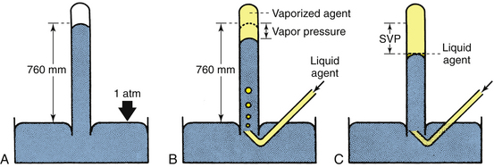
FIGURE 3-1 Measurement of vapor pressures using a simple Fortin barometer. SVP, saturated vapor pressure. (From Eisenkraft JB: Vaporizers and vaporization of volatile anesthetics. In Progress in anesthesiology, vol 2. San Antonio, 1989, Dannemiller Memorial Educational Foundation.)
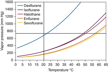
In Figure 3-1, B, sevoflurane liquid is introduced at the bottom of the mercury column. Being less dense than mercury, it rises to the top and evaporates into the space created by the Torricellian vacuum. The sevoflurane vapor exerts pressure and causes an equivalent decrease in the height of the mercury column. If liquid sevoflurane is added until a small amount remains unevaporated on the top of the mercury meniscus (Fig. 3-1, C), the space above the column must be fully saturated with vapor; the pressure now exerted by the vapor is the SVP of sevoflurane at that temperature, and adding more liquid sevoflurane will not affect the vapor pressure. If this experiment is repeated at different temperatures, a graph can be constructed that plots SVP against temperature. Such curves for some of the potent inhaled volatile anesthetic agents are shown in Figure 3-2. Contemporary technologies for measuring the partial pressures or SVPs of gases and vapors are described in Chapter 8.
Boiling Point
The SVP exerted by the vapor phase of a potent inhaled volatile agent is a physical property of that agent and depends only on the agent and the ambient temperature. The temperature at which SVP becomes equal to ambient (atmospheric) pressure and that at which all the liquid agent changes to the vapor phase (i.e., evaporates) is the boiling point of that liquid. Water boils at 100° C at 1 atm because at 100° C, the SVP of water is 760 mm Hg. The most volatile of the agents are those with the highest SVPs at room temperature. At any given temperature, these agents also have the lowest boiling points: desflurane and diethyl ether boil at 22.9° C and 35° C, respectively, at an ambient pressure of 760 mm Hg. Boiling point decreases with decreasing ambient barometric pressure, such as occurs at increasing altitude.
Units of Vapor Concentration
The presence of anesthetic vapor may be quantified either as an absolute pressure, expressed in millimeters of mercury (mm Hg) (or, less commonly, kilopascals [kPa]) or in volumes percent (vol%) of the total atmosphere (i.e., volumes of vapor per 100 volumes of total gas). From Dalton’s law of partial pressures, the volumes percent can be calculated as the fractional partial pressure of the agent:
Dalton’s Law of Partial Pressures
Dalton’s law states that the pressure exerted by a mixture of gases, or gases and vapors, enclosed in a given space such as a container is equal to the sum of the pressures that each gas or vapor would exert if it alone occupied that given space or container.4 A gas or vapor exerts its pressure independently of the pressure of the other gases present. For example, in a container of dry air at 1 atm (760 mm Hg), with oxygen representing 21% of all gases present, the pressure exerted by the oxygen—its partial pressure—is 159.6 mm Hg (21% × 760). Consider the same air at a pressure of 760 mm Hg but fully saturated with water vapor at 37° C (normal body temperature). Because vapor pressure depends on temperature, the SVP for water at 37° C is 47 mm Hg. The pressure from oxygen is therefore now 21% of 713 (i.e., 760 − 47) mm Hg. The partial pressure of oxygen is therefore 149.7 mm Hg.
Note that volumes percent expresses the relative ratio or proportion (%) of gas molecules in a mixture, whereas partial pressure (mm Hg) represents an absolute value. Anesthetic uptake and potency are directly related to partial pressure and only indirectly to volumes percent. This distinction become more apparent when hyperbaric and hypobaric conditions are considered.
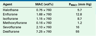
Minimum Alveolar Concentration
The minimum alveolar concentration (MAC) of a potent inhaled anesthetic agent is the concentration that produces immobility in 50% of patients who undergo a standard surgical stimulus. Used as a measure of anesthetic potency or depth, MAC is commonly expressed as volumes percent of alveolar (end-tidal) gas at 1 atm pressure at sea level (i.e., 760 mm Hg). Table 3-1 shows how MAC expressed in familiar volumes percent can be expressed as a partial pressure in millimeters of mercury. Anesthesiologists should learn to think of MAC in terms of partial pressure rather than in terms of volumes percent because the partial pressure (tension) of the anesthetic in the central nervous system is responsible for the depth of anesthesia. This concept has been advocated by Fink,5 who proposed the term minimum alveolar pressure (MAP), and by James and White,6 who suggested minimum alveolar partial pressure (MAPP). In this text, the term PMAC1 (see Table 3-1) is used to express the partial pressure of a potent inhaled agent at a concentration of 1 MAC; thus 1 MAC of isoflurane is equivalent to a PMAC1 of 8.7 mm Hg.
Latent Heat of Vaporization
Vaporization requires energy to transform molecules from the liquid phase to the vapor phase. This energy is called the latent heat of vaporization and is defined as the amount of heat (calories) required to convert a unit mass (grams) of liquid into vapor. For example, at 20° C the latent heat of vaporization of isoflurane is 41 cal/g. The heat of vaporization is inversely related to ambient temperature in such a way that at lower temperatures, more heat is required for vaporization. The heat required to vaporize an anesthetic agent is drawn from the remaining liquid agent and from the surroundings. As vapor is generated and heat energy is lost, the temperatures of the vaporizer and the liquid agent fall. This causes the vapor pressure of the anesthetic to decrease. If no compensatory mechanism is provided, this will result in decreased output of vapor.
Specific Heat
Specific heat is the quantity of heat (calories) required to raise the temperature of a unit mass (grams) of a substance by 1° C. Heat must be supplied to the liquid anesthetic in the vaporizer to maintain the liquid’s temperature during the evaporation process, when heat is being lost.
Specific heat is also important when it comes to vaporizer construction material. For the same amount of heat lost through vaporization, temperature changes are more gradual for materials with a high specific heat than for those with a low specific heat. Thermal capacity, defined as the product of specific heat and mass, represents the quantity of heat stored in the vaporizer body.
Also of importance is the construction material’s ability to conduct heat from the environment to the liquid anesthetic. This property is called thermal conductivity, defined as the rate at which heat is transmitted through a substance. For the liquid anesthetic to remain at a relatively constant temperature, the vaporizer is constructed from materials that have a high specific heat and high thermal conductivity. In this respect, copper comes close to the ideal; however, bronze and stainless steel have been used more recently in vaporizer construction.
Regulating Vaporizer Output: Variable Bypass Versus Measured Flow
The SVPs of halothane, sevoflurane, and isoflurane at room temperature are 243, 160, and 241 mm Hg, respectively. Dividing the SVP by ambient pressure (760 mm Hg) gives the saturated vapor concentration (SVC) as a fraction (or percentage) of 1 atm. This is an application of Dalton’s law, as discussed earlier. The SVCs of halothane, sevoflurane, and isoflurane are therefore 32%, 21%, and 31%, respectively. These concentrations are far in excess of those required clinically (Table 3-2). Therefore the vaporizer first creates a saturated vapor in equilibrium with the liquid agent; second, the saturated vapor is diluted by a bypass gas flow. This results in clinically safe and useful concentrations flowing to the patient’s breathing circuit. Without this dilution of saturated vapor, the agent would be delivered in a lethal concentration to the anesthesia circuit.
TABLE 3-2
Physical Properties of Potent Inhaled Volatile Agents
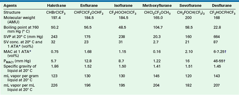
AMU, atomic mass units; conc., concentration; MAC, minimum alveolar concentration; PMAC1, partial pressure of a potent inhaled agent at a concentration of 1 MAC; SVC, saturated vapor concentration; SVP, saturated vapor pressure.
∗1 ATA = one atmosphere absolute pressure (760 mm Hg).
†Age related.
Contemporary anesthesia vaporizers are concentration calibrated, and most are of the variable bypass design. In a variable bypass vaporizer, such as those made by GE Healthcare (Tec series) and the Dräger Vapor 2000 (Dräger Medical, Telford, PA), the total fresh gas flow from the anesthesia machine flowmeters passes to the vaporizer (Fig. 3-3). The vaporizer splits the incoming gas flow between two pathways: the smaller flow enters the vaporizing chamber, or sump, of the vaporizer and leaves it with the anesthetic agent at its SVC. The larger bypass flow is eventually mixed with the outflow from the vaporizing chamber to create the desired, or “dialed in,” concentration (see Fig. 3-3).
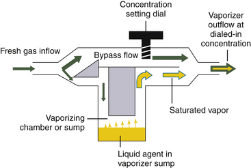
FIGURE 3-3 Schematic of a concentration-calibrated variable bypass vaporizer. Fresh gas enters the vaporizer, where its flow is split between a larger bypass flow and a smaller flow to the vaporizing chamber or sump. In the sump is the agent at its saturated vapor concentration. Saturated vapor mixes with the bypass flow, which dilutes it to the concentration dial setting.
In the now-obsolete measured flow, non-concentration-calibrated vaporizers such as the Copper Kettle (Puritan-Bennett; Covidien, Mansfield, MA) or Verni-Trol (Ohio Medical Products, Gurnee, IL), a measured flow of oxygen is set on a separate flowmeter to pass to the vaporizer, from which vapor emerges at its SVP (Fig. 3-4). This flow is then diluted by an additional measured flow of gases (oxygen, nitrous oxide, air, etc.) from the main flowmeters on the anesthesia machine. With this type of arrangement, calculations are necessary to determine the anesthetic vapor concentration in the emerging gas mixture.
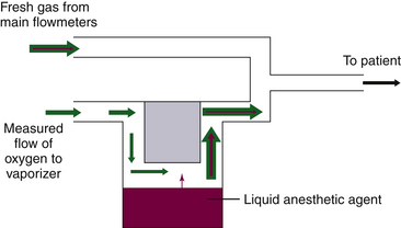
FIGURE 3-4 Schematic of a measured flow vaporizing arrangement. These are commonly known as “bubble-through” vaporizers.
With both types of vaporizing systems, there must be an efficient method to create a saturated vapor in the vaporizing chamber. This is achieved by having a large surface area for evaporation. Flow-over vaporizers (Dräger Vapor 2000 series, GE Tec series) increase the surface area using wicks and baffles. In measured flow, bubble-through vaporizers, oxygen is bubbled through the liquid agent. To increase the surface area, tiny bubbles are created by passing the oxygen through a sintered bronze disk in the Copper Kettle, for example, which created large areas of liquid/gas interface, over which evaporation of the liquid agent could quickly occur.
Calculation of Vaporizer Output
At a constant room temperature of 20° C, the SVPs of two commonly used potent inhaled agents are 160 mm Hg for sevoflurane and 238 mm Hg for isoflurane. If ambient pressure is 760 mm Hg, these SVPs represent 21% sevoflurane (160/760) and 31% isoflurane (239/760), each in terms of volumes percent of 1 atm (760 mm Hg).
A concept fundamental to understanding vaporizer function is that under steady-state conditions, if a certain volume of carrier gas flows into a vaporizing chamber over a certain period, that same volume of carrier gas exits the chamber over the same period. However, because of the addition of vaporized anesthetic agent, the total volume exiting the chamber is greater than that entering it. In the vaporizing chamber, anesthetic vapor at its SVP constitutes a mandatory fractional volume of the atmosphere (i.e., 21% in a sevoflurane vaporizer at 20° C and 760 mm Hg). Therefore the volume of carrier gas will constitute the difference between 100% of the atmosphere in the vaporizing chamber and that resulting from the anesthetic vapor. In the case of sevoflurane, the carrier gas represents 79% of the atmosphere in the vaporizing chamber at any time. Thus if 100 mL/min of carrier gas flows through a vaporizing chamber containing sevoflurane, the carrier gas represents 79% (100% − 21%) of the atmosphere and the remaining 21% is sevoflurane vapor. By simple proportions, the volume of sevoflurane vapor exiting the chamber can be calculated to be 27 mL ([100/79] × 21) when rounded to the nearest whole number.
In other words, if 100 mL/min of carrier gas flows into the vaporizing chamber, the same 100 mL of carrier gas will emerge together with 27 mL/min of sevoflurane vapor. Another way of expressing this is shown below:
Continuing the above example for sevoflurane, y is 100 mL/min, and 160/760 = x/(100 + x), from which x can be calculated as 27 mL (rounded to the nearest whole number). Conversely, if x is known, the carrier gas flow y can be calculated. At steady state, the total volume of gas leaving the vaporizing chamber is greater than the total volume that entered, the additional volume being anesthetic vapor at its SVC.
Vaporizer Function
Although measured flow vaporizers are not mentioned in the ASTM anesthesia machine standards published after 1988, it is helpful to review the function of one example, the Copper Kettle. If 1% (vol/vol) isoflurane must be delivered to the patient circuit at a total fresh gas flow rate of 5 L/min (Fig. 3-5), the vaporizer must evolve 50 mL/min of sevoflurane vapor (1% × 5000 mL) to be diluted in a total volume of 5000 mL.
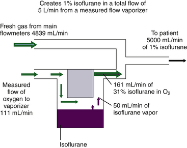
FIGURE 3-5 Preparation of 1% isoflurane by volume using a measured flow vaporizing system. 1% isoflurane in a 5L/min flow requires 50 mL/min isoflurane vapor, diluted in a total volume of 4950 mL fresh gas plus 50 mL isoflurane vapor. Isoflurane saturated vapor concentration is 31%. If 31% = 50 mL, then 69% = 111 mL, the required oxygen inflow per minute; 4839 mL/min (4950 − 111) is the required bypass flow, and final dilution is 1% (50/[50 + 4839 + 111]).
In the Copper Kettle, isoflurane represents 31% of the atmosphere, assuming a constant temperature of 20° C and a constant SVP of 238 mm Hg. If 50 mL of isoflurane vapor represents 31%, the carrier gas flow (x mL) of, oxygen flow x must represent the other 69% (100% − 31%). Thus


Therefore, if 111 mL/min of oxygen is bubbled through liquid isoflurane in a Copper Kettle vaporizer, 161 mL/min of gas emerges, of which 50 mL is isoflurane vapor and 111 mL is the oxygen that flowed into the vaporizer. This vaporizer output of 161 mL/min must be diluted by an additional fresh gas flow of 4839 mL/min (5000 mL − 161 mL) to create an isoflurane mixture of exactly 1% because 50 mL of isoflurane vapor diluted in a total volume of 5000 mL gives 1% isoflurane by volume.
Although this situation is highly unlikely to occur in contemporary practice because of the obsolescence of measured flow vaporizers, if a measured flow system had to be used to deliver isoflurane, the anesthesia provider would likely set flows of 100 mL/min oxygen to the Copper Kettle and 5 L/min of fresh gas on the main flowmeters, which would result in only slightly less than 1% isoflurane (44.9/5044.9 = 0.89%). Multiples of either of the vaporizer oxygen flow and main gas flowmeter flows would be used to create other concentrations of isoflurane from the Copper Kettle. Thus a 200 mL/min oxygen flow to the vaporizer and 5000 mL/min on the main flowmeters would create approximately 1.8% isoflurane. It is important to realize that if there is oxygen flow only to the Copper Kettle vaporizer and no bypass gas flow is set on the main machine flowmeters, lethal concentrations approaching 31% isoflurane would be delivered to the anesthesia circuit, albeit at low flow rates.
Because halothane and isoflurane have similar SVPs at 20° C, the Copper Kettle flows to be set for halothane would be essentially the same as those for isoflurane when a 1% concentration of isoflurane is to be created with a Copper Kettle. A Copper Kettle arrangement on an older model anesthesia machine is shown in Figure 3-6.
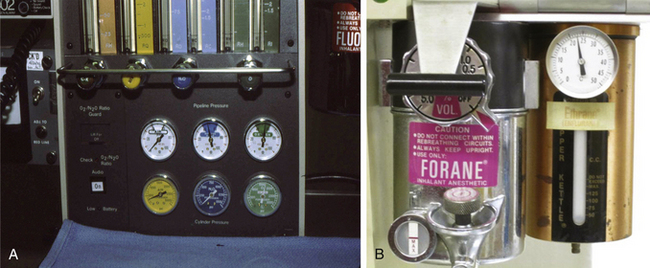
FIGURE 3-6 Copper Kettle vaporizing system (Puritan-Bennett; Covidien, Mansfield, MA). A, The oxygen flowmeter knob on the extreme left is marked “C-K” to indicate that it controls oxygen flow to the Copper Kettle. B, Close-up of the Copper Kettle.
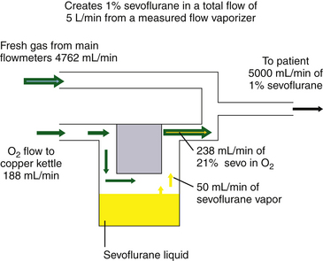
Because enflurane and sevoflurane have similar vapor pressures at 20° C (175 mm Hg and 160 mm Hg, respectively), similar flow settings could be used to create approximately the same agent concentrations with a measured flow system. In the case of sevoflurane, the measured flow vaporizer contains 21% sevoflurane vapor (160/760 = 21%). The oxygen flow therefore represents the remaining 79% of the atmosphere in the Copper Kettle. If precisely 1% sevoflurane is required at a 5 L/min total rate of flow, 50 mL/min of sevoflurane vapor must be generated. If 50 mL represents 21% of the atmosphere in the vaporizer, the carrier gas flow required is 188 mL/min ([50/21] × 79).
If 188 mL/min of oxygen are bubbled through liquid sevoflurane contained in a measured flow vaporizer, 238 mL/min of gas will emerge, 50 mL/min of which is sevoflurane vapor. This must be diluted by a fresh gas flow of 4762 mL/min (5000 − 238) to achieve exactly 1% sevoflurane.
Alternatively, using the formula given previously:


where y is the oxygen flow to the measured flow vaporizer.
Setting an oxygen flow of 200 mL/min to the vaporizer and 5 L/min on the main flowmeters would result in a sevoflurane concentration of 1.01%, or ([200/79] × 21)/5253.2.
In the preceding examples, calculations of both the oxygen flow to the measured flow vaporizer and the total bypass gas flow needed to produce the desired output concentrations of vapor were required. This is not only inconvenient, it also predisposes to clinical errors that could result in serious overdose (Fig. 3-7) or underdose of anesthetic. Because of the obvious potential for error with a measured flow vaporizing system, the concurrent continuous use of an anesthetic agent analyzer with high- and low-concentration alarms would be essential for patient safety.7
Variable Bypass Vaporizers
In the concentration-calibrated variable bypass vaporizer, the total flow of gas arriving from the anesthesia machine flowmeters is split between a variable bypass and the vaporizing chamber containing the anesthetic agent (see Fig. 3-3). The ratio of these two flows, known as the splitting ratio, depends on the anesthetic agent, temperature, and chosen vapor concentration set to be delivered to the patient circuit.
As previously discussed, to deliver 1% sevoflurane accurately, a total incoming gas flow of 4950 mL/min must be split so that 188 mL/min flows through the vaporizing chamber and 4762 mL/min flows through the bypass. This results in a splitting ratio of 25:1 (4762/188) between the bypass flow and the vaporizing chamber flow at a temperature of 20° C. A variable bypass vaporizer set to deliver 1% sevoflurane is therefore effectively set to create a splitting ratio of 25:1 for the inflowing gas (Fig. 3-8).
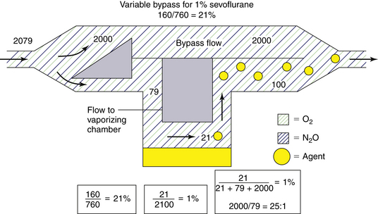
FIGURE 3-8 Preparation of 1% (vol/vol) sevoflurane in a variable bypass vaporizer. To achieve this, a split ratio of 25:1 (bypass flow/vaporizing chamber flow) is created for incoming gas.
Consider a concentration-calibrated, variable bypass, isoflurane-specific vaporizer set to deliver 1% isoflurane. What splitting ratio for incoming gases must this vaporizer achieve? The SVP of isoflurane at 20° C is 238 mm Hg; therefore the concentration of isoflurane vapor in the vaporizing chamber is 31% (238/760). If carrier gas flows through the vaporizing chamber at a rate of 69 mL/min, isoflurane vapor emerges at 31 mL/min and must be diluted in 3100 mL/min of total gas flow to achieve a 1% concentration because 31/3100 equals 1%. Thus, if carrier gas enters the vaporizer from the flowmeters at 3069 mL/min and is split—such that 3000 mL/min flows through the bypass and 69 mL/min flows through the vaporizing chamber—when the two flows merge, 1% isoflurane is the result. The splitting ratio is therefore 44:1 (3000/69) (Fig. 3-9).
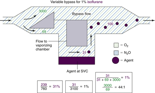
FIGURE 3-9 Preparation of 1% (vol/vol) isoflurane by a variable bypass vaporizer. To achieve this, a split ratio of 44:1 (bypass flow/vaporizing chamber flow) is created for incoming gas.
Table 3-3 shows the splitting ratios for variable bypass vaporizers used at 20° C. To ensure complete understanding, the reader is encouraged to calculate these ratios and apply them to different total fresh gas flows arriving from the main flowmeters to the inlet of a concentration-calibrated variable bypass vaporizer. An equation for the calculation of splitting ratios is provided in the Appendix to this chapter.
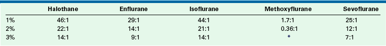
The concentration-calibrated vaporizer is agent specific and must be used only with the agent for which the unit is designed and calibrated. To produce a 1% vapor concentration, an isoflurane vaporizer makes a flow split of 44:1, whereas a sevoflurane vaporizer makes a flow split of 25:1 (see Table 3-3). If an empty sevoflurane vaporizer set to deliver a 1% concentration were to be filled with isoflurane, the concentration of the isoflurane vapor emerging would be in excess of 1%. Understanding splitting ratios enables prediction of the concentration output of an empty, agent-specific, variable bypass vaporizer that has been erroneously filled with an agent for which it was not designed. The change in concentration output when one agent-specific vaporizer is filled with a different agent can be calculated as the concentration set on the vaporizer dial multiplied by the ratio of the splitting ratios at 20° C (and not as the ratio of the SVPs of the two agents). In the case of the sevoflurane vaporizer set to deliver 1% sevoflurane but filled with isoflurane, the resulting isoflurane concentration will be 1.76% isoflurane (44/25).
Control of Splitting Ratio
In a variable bypass vaporizer, the bypass flow and the vaporizing chamber flow may be thought of as two resistances in parallel. The concentration control dial is used to adjust the ratio of the two resistances to achieve the dialed-in concentration by adjusting the size of a variable orifice. That orifice may be located at the inlet of the vaporizing chamber or at the outlet. In older model vaporizers the variable orifice was located at the inlet to the vaporizing chamber (see Fig. 8-11 in Chapter 8 for an example). In contemporary vaporizers (e.g., GE Healthcare Tec 5; Dräger Medical Vapor 19.n series) the orifice is located at the outlet of the chamber (see Fig. 3-19). The splitting ratios discussed in the previous section describe the effective flow split for the fresh gas entering the vaporizer but not where the split is achieved (i.e., whether by the inlet or the outlet of the vaporizing chamber). If the split is achieved at the outlet of the vaporizing chamber, a flow of saturated vapor is metered into the bypass flow and an “exit” splitting ratio can be calculated. In Figure 3-8, to create 1% sevoflurane a controlled flow of 100 mL/min of 21% sevoflurane is mixed with the bypass flow of 2000 mL/min. The ratio of flows is 2000/100 = 20:1. Compare this with the effective flow split of 25:1 for the fresh gas entering the vaporizer from the machine flowmeters.
Similarly, in Figure 3-9, to create 1% isoflurane a controlled flow of 100 mL/min of 31% isoflurane vapor is mixed with the bypass flow of 3000 mL/min; the “exit” splitting ratio is 3000/100 = 30:1. Compare this with the effective flow split of 44:1 for the fresh gas entering the vaporizer.
The location of the variable orifice is of little importance at 1 atm pressure but may have an effect when the vaporizer is used at ambient pressures that are higher or lower than 1 atm. (see later section on Effects of Changes in Barometric Pressure).
Efficiency and Temperature Compensation
Agent-specific concentration-calibrated vaporizers must be located in the fresh gas path between the flowmeter manifold outlet and the common gas outlet on the anesthesia workstation.3 The vaporizers must be capable of accepting a total gas flow of 15 L/min from the machine flowmeters and be able to deliver a predictable concentration of vapor.3 However, as the agent is vaporized and the temperature falls, SVP also falls. In the case of a measured flow vaporizer or an uncompensated variable bypass vaporizer, this results in delivery of less anesthetic vapor to the patient circuit. For this reason, all vaporizing systems must be temperature compensated, either manually or, as in contemporary vaporizers, automatically.
Measured flow vaporizers incorporate a thermometer that measures the temperature of the liquid agent in the vaporizing chamber. A higher temperature translates to a higher SVP in this chamber. Reference to the vapor pressure curves (see Fig. 3-2) enables a resetting of either oxygen flow to the vaporizer, bypass gas flow, or both to ensure correct output at the prevailing temperature. Although tedious, such an arrangement does ensure the most accurate and rapid temperature compensation. The original Dräger Vapor vaporizer (Fig. 3-10), to be distinguished from the more recent Vapor 19.n and 2000 models fitted to contemporary Dräger workstations, is a variable bypass vaporizer that incorporates a thermometer and a grid of lines on the vaporizer control dial for temperature compensation by which the desired output concentration is matched to the temperature of the liquid agent; turning the control dial changes the size of an orifice in the bypass flow.
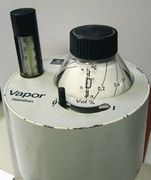
FIGURE 3-10 In the Dräger Vapor vaporizer (Dräger Medical, Telford, PA), temperature compensation is achieved by reading the temperature from the thermometer and using the control dial to align the desired output concentration (slanting) line with the marking for ambient temperature.
Most of the contemporary variable bypass vaporizers, such as the Tec series and the Dräger Vapor 19.n and 2000, achieve automatic temperature compensation via a temperature-sensitive valve in the bypass gas flow. When temperature increases, the valve in the bypass opens wider to create a higher splitting ratio so that more gas flows through the bypass and less gas enters the vaporizing chamber. A smaller volume of a higher concentration of vapor emerges from the vaporizing chamber; this vapor, when mixed with an increased bypass gas flow, maintains the vaporizer’s output at reasonable constancy when temperature changes are not extreme.
Temperature-sensitive valves have evolved in design among the different types of vaporizers. Some older vaporizers, such as the Ohio Medical Calibrated Vaporizer, had in the vaporizing chamber, a gas-filled bellows linked to a valve in the bypass gas flow (Fig. 3-11).8 As the temperature increased, the bellows expanded, causing the valve to open wider. Contemporary vaporizers, such as the Tec series, use a bimetallic strip for temperature compensation.9 This strip is incorporated into a flap valve in the bypass gas flow. The valve is composed of two metals with different coefficients of expansion, or change in length per unit length per unit change in temperature. Nickel and brass have been used in bimetallic strip valves because brass has a greater coefficient of expansion than nickel. As the temperature rises, one surface of the flap expands more than the other, causing the flap to bend in a manner that opens the valve orifice wider, increasing the bypass flow. The principle of differential expansion of metals is applied similarly in the Dräger Vapor 19.n and 2000 series vaporizers, in which an expansion element increases bypass flow and reduces gas flow in the vaporizing chamber as temperature increases.10 When temperature decreases, the reverse occurs.
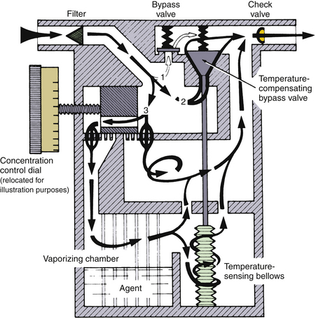
FIGURE 3-11 Schematic of a calibrated vaporizer. Temperature compensation is achieved by a gas-filled temperature-sensing bellows that controls the size of a temperature-compensating bypass valve. Note also the check valve in the vaporizer outlet designed to protect against the pumping effect. (Courtesy GE Healthcare, Waukesha, WI.)
The vapor pressures of the volatile anesthetics vary as a function of temperature in a nonlinear manner (see Fig. 3-2). The result is that the vapor output concentration at any given vaporizer dial setting remains constant only within a certain range of temperatures. For example, the Dräger Vapor 2000 vaporizers are specified as accurate to ±0.20 vol% or ±20% of the concentration set when they are used within the temperature range of 15° C to 35° C at 1 atm.11 The boiling point of the volatile anesthetic agent must never be reached in the current variable bypass vaporizers designed for halothane, enflurane, isoflurane, and sevoflurane; otherwise, the vapor output concentration would be impossible to control and could be lethal.
Temperature Compensation Times
The temperature-compensating mechanisms of contemporary vaporizers do not produce instantaneous correction of output concentration. For example, the Dräger 19.n vaporizer requires a temperature compensation time of 6 min/° C.12
Incorrect Filling of Vaporizers
Contemporary concentration-calibrated variable bypass anesthesia vaporizers are agent specific. If an empty vaporizer designed for one agent is filled with an agent for which it was not intended, the vaporizer’s output will likely be erroneous. Because the vaporizing characteristics of halothane and isoflurane (SVP of 243 and 238 mm Hg, respectively) and enflurane and sevoflurane (SVP of 175 and 160 mm Hg, respectively) are almost identical at room temperature, this problem mainly applies when halothane or isoflurane is interchanged with enflurane or sevoflurane.
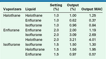
Bruce and Linde13 reported on the output of erroneously filled vaporizers (Table 3-4). Erroneous filling affects the output concentration and, consequently, the potency output of the vaporizer. In their study, an enflurane vaporizer set to 2% (1.19 MAC) but filled with halothane delivered 3.21% (4.01 MAC) halothane. This is 3.3 times the anticipated anesthetic potency output.
TABLE 3-4
Output in Volumes Percent and Minimum Alveolar Concentration (MAC in Oxygen) of Erroneously Filled Vaporizers at 22° C
MAC, minimum alveolar concentration.
From Bruce DL, Linde HW: Vaporization of mixed anesthetic liquids. Anesthesiology 60:342-346, 1984.
To summarize, if a vaporizer specific for an agent with a low SVP, such as enflurane or sevoflurane, is misfilled with an agent that has a high SVP, such as halothane or isoflurane, the output concentration of the agent will be greater than that indicated on the concentration dial. Conversely, if a vaporizer specific for an agent with a high SVP is misfilled with an agent that has a low SVP, the output concentration of the agent will be less than that indicated on the concentration dial.
In addition, the potency of the agent concentration must be considered in a misfilling situation. A sevoflurane vaporizer set to deliver 2% sevoflurane (1 MAC) misfilled with isoflurane would produce an isoflurane concentration of 3.5% (~3 MAC).
Erroneous filling of vaporizers may be prevented if careful attention is paid to the specific agent and the vaporizer during filling. A number of agent-specific filling mechanisms analogous to the pin index safety system for medical gases are used on modern vaporizers. Liquid anesthetic agents are packaged in bottles that have agent-specific and color-coded collars (Fig. 3-12). One end of an agent-specific filling device fits the collar on the agent bottle, and the other end fits only the vaporizer designed for that liquid agent. Although well designed, these filling devices cannot entirely prevent misfilling.
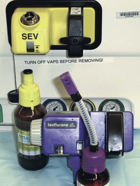
FIGURE 3-12 Agent-specific filling devices for sevoflurane (yellow;Quik-Fil, Abbott Laboratories, Abbott Park, IL) and isoflurane (purple;Key-Fill, Harvard Apparatus, Holliston, MA).
A number of different filling systems are available (e.g., Quik-Fil [Abbott Laboratories, Abbott Park, IL], Key-Fill [Harvard Apparatus, Holliston, MA]). The agent-specific filling device for desflurane, SAF-T-FILL (Zeneca Pharma, Inc., Mississauga, Canada), is particularly important because a non-desflurane vaporizer must never be filled with desflurane.
Vaporization of Mixed Anesthetic Liquids
Perhaps a more likely scenario is that an agent-specific vaporizer, partially filled with the correct agent, is topped off with an incorrect agent. This situation is more complex because it is much more difficult to predict vaporizer output, and significant errors in concentration of delivered vapor can occur. Korman and Ritchie reported that halothane, enflurane, and isoflurane do not react chemically when mixed, but they do influence the extent of each other’s ease of vaporization. Halothane facilitates the vaporization of both enflurane and isoflurane and is itself more likely to vaporize in the process.14 The clinical consequences depend on the potencies of each of the mixed agents and on the delivered vapor concentrations.
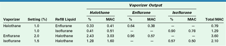
If a halothane vaporizer that is 25% full is filled to 100% with isoflurane and set to deliver 1%, the halothane output is 0.41% (0.51 MAC) and the isoflurane output is 0.9% (0.78 MAC; see Table 3-5). In this case, the output potency of 1.29 MAC is not far from the anticipated 1.25 MAC (1% halothane). On the other hand, an enflurane vaporizer that is 25% full and set to deliver 2% (1.19 MAC) enflurane filled to 100% with halothane has an output of 2.43% (3.03 MAC) halothane and 0.96% (0.57 MAC) enflurane. This represents a total MAC of 3.60—more than three times the intended amount.
TABLE 3-5
Vaporizer Output After Incorrectly Refilling from 25% Full to 100% Full
MAC, minimum alveolar concentration.
From Bruce DL, Linde HW: Vaporization of mixed anesthetic liquids. Anesthesiology 60:342-346, 1984.
If a vaporizer filling error is suspected, the vaporizer should be emptied and flushed using 5 L/min of oxygen (in the case of the Tec 4), with the concentration dial set to the maximum output, until no trace of the contaminant is detected in the outflow.15,16 The vaporizer’s temperature should then be allowed to stabilize for 2 hours before it is used clinically, and with great caution. If the contaminant is not volatile, such as with water, the vaporizer should be returned to the manufacturer for servicing.
Contemporary anesthetic vaporizers now incorporate agent-specific filling devices designed to prevent erroneous filling and to reduce contamination of the atmosphere in the operating room while the vaporizing chamber is being filled.
Filling of Vaporizers
Vaporizers should be filled only in accordance with their manufacturer’s instructions. Overfilling or tilting a vaporizer—that is, either tilting a freestanding unit or tilting the whole anesthesia machine—may result in liquid agent entering parts of the anesthesia delivery system designed for gases and vapor only, such as a vaporizer bypass. This could lead to the delivery of lethal concentrations of agent to the patient circuit. If a vaporizer has been tilted, liquid agent may have leaked into the gas delivery system. A patient must never be left connected to such a system. Once the machine has been withdrawn from clinical service, the proper procedure is to purge the vaporizer with a high flow rate of oxygen from the flowmeter of the anesthesia machine or workstation—not the oxygen flush, which bypasses the vaporizer—and with the vaporizer concentration dial set to the maximum concentration.12,15 The maximum concentration dial setting ensures the highest possible oxygen flow through the inflow and outflow paths of the vaporizing chamber and through the bypass. A calibrated anesthetic agent analyzer is essential to check the efficacy of the flush procedure before the vaporizer is returned to clinical service. In contemporary practice, it is probably prudent to withdraw the workstation and vaporizer from clinical use until both have been declared safe by authorized service personnel.
Table 3-2 shows that 1 mL of liquid volatile agent produces approximately 200 mL of vapor at 20° C. The theoretical derivation of this volume is presented later in this chapter (see Preparation of a Standard Vapor Concentration). Thus it is easy to see how very small volumes of liquid agent entering the gas delivery system might produce lethal concentrations. For example, if 1 mL of liquid isoflurane entered the common gas tubing, some 20 L of fresh gas would be required to dilute the resulting volume of vapor (195 mL) down to a 1% (0.87 MAC) concentration.
Effect of Carrier Gas on Vaporizer Output
The carrier gas used to vaporize the volatile agent in the vaporizing chamber can also affect vaporizer output because the viscosity and density of the gas mixture change as the mixture changes. Figure 3-13 shows the output concentration from an enflurane variable bypass vaporizer set to deliver 1% enflurane. For the first 10 minutes, the carrier gas is 70% nitrous oxide and 30% oxygen and the vaporizer delivers 1% enflurane. After 10 minutes, the carrier gas is changed to nitrogen and oxygen; at approximately 20 minutes, the vaporizer output is seen to increase to a peak of about 2.6%; at 30 minutes, it decreases to 1%, at which point it stabilizes. At 40 minutes, the carrier gas is changed back to nitrous oxide and oxygen, and the vaporizer output concentration transiently decreases to 0.75%. By 55 minutes, it gradually returns to 1%. At 60 minutes, the carrier gas is changed back to nitrogen and oxygen and the vaporizer output again increases.
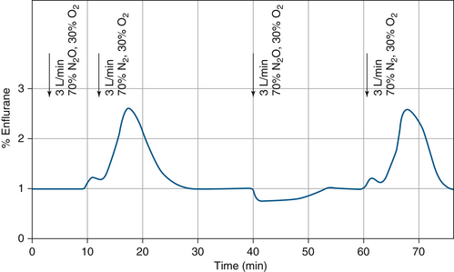
FIGURE 3-13 Effect of changing the carrier gas composition (nitrous oxide vs. nitrogen) on vaporizer output in a variable bypass enflurane vaporizer. (From Scheller MS, Drummond JC: Solubility of N2O in volatile anesthetics contributes to vaporizer aberrancy when changing carrier gases. Anesth Analg 1986;65:88-90. Reproduced by permission of the International Anesthesia Research Society.)
The effect of carrier gas on vaporizer output can be explained by the solubility of nitrous oxide in a liquid volatile anesthetic agent. Thus, when nitrous oxide and oxygen begin to enter the vaporizing chamber, some nitrous oxide dissolves in the liquid agent, and the vaporizing chamber’s output decreases until the liquid agent has become saturated with nitrous oxide. Conversely, when nitrous oxide is withdrawn as the carrier gas, the nitrous oxide dissolved in the liquid anesthetic comes out of solution and represents, in effect, additional nitrous oxide gas flow to the vaporizing chamber.
The solubility of nitrous oxide in liquid anesthetics is approximately 4.5 mL per milliliter of liquid anesthetic17; therefore 100 mL of enflurane liquid, when fully saturated, can dissolve approximately 450 mL of nitrous oxide. When nitrous oxide is discontinued because it is added (by coming out of solution) to the vaporizing chamber flow over a brief period, the volume of nitrous oxide causes the observed increase in vaporizer output concentration.
Dräger vaporizers are calibrated using air as the carrier gas. When 100% oxygen is used, the output concentration, when compared with air, increases by 10% of the set value and by not more than 0.4 vol%. When a mixture of 30% oxygen and 70% nitrous oxide is used, the concentration falls by 10% of the set value at most and by not more than 0.4 vol%.11 Tec series vaporizers are calibrated at 21° C with oxygen as the carrier gas. In these vaporizers, when air or nitrous oxide is the carrier gas, the output concentration is less than with oxygen. The effect is greatest when nitrous oxide is the carrier gas, but using nitrous oxide decreases the required concentration of volatile agent, thereby somewhat mitigating the decrease in output concentration.18
Effects of Changes in Barometric Pressure
Vaporizers are most commonly used at an ambient pressure of 760 mm Hg (1 atm at sea level). They may, however, be used under hypobaric conditions, such as at high altitudes, or under hyperbaric conditions, such as in a hyperbaric chamber.5
Vaporizing Chamber Flow Controlled at Inlet
When used at pressures above or below 1 atm, the location of the variable orifice controlling flow into or out from the vaporizing chamber affects vaporizer performance.
Hypobaric Conditions
Few reports are available concerning the use of vaporizers under hypobaric conditions.6 This discussion therefore focuses on theoretical considerations applying to such use.
Consider a variable bypass vaporizer set to deliver 1% sevoflurane (0.5 MAC at 760 mm Hg atmospheric pressure) at an ambient pressure of 500 mm Hg, equivalent to an altitude of approximately 12,000 feet above sea level, and at a temperature of 20° C (Fig. 3-14). In the vaporizing chamber, sevoflurane has an SVP of 160 mm Hg at a temperature of 20° C; however, this now represents 32 vol% (160/500) of the atmosphere there. Set to deliver 1% under normal conditions, for the incoming fresh gas the vaporizer creates a splitting ratio of 25:1 between bypass and vaporizing chamber flows.
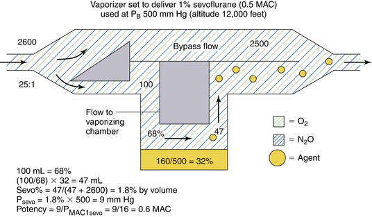
FIGURE 3-14 Use of a concentration-calibrated variable bypass sevoflurane vaporizer under hypobaric conditions. MAC, minimum alveolar concentration; PB, barometric pressure; PMAC1, partial pressure of a potent inhaled agent at a concentration of 1 MAC.
If the total gas flow to the vaporizer is 2600 mL/min (Fig. 3-14), 100 mL/min of carrier gas flows through the vaporizing chamber. This now represents 68% of the volume there because sevoflurane represents the other 32 vol% (100% − 68%). Emerging from the vaporizing chamber is 100 mL/min of carrier gas plus 47 mL/min of sevoflurane vapor ([100/68] × 32). When the vaporizing chamber and bypass flows merge, the 47 mL/min of sevoflurane vapor are diluted in a total volume of 2647 mL/min (2500 + 100 + 47 mL), giving a sevoflurane concentration of 1.8% of the atmosphere by volume. This appears to be almost twice (1.8 times) the dialed-in concentration in terms of volumes percent.
To determine the potency of this 1.8% sevoflurane concentration, however, partial pressure must be considered because it is the tension of the anesthetic agent that determines potency. If sevoflurane represents 1.8% of the gas mixture by volume, its partial pressure in the emerging mixture is 1.8% × 500 mm Hg, or 9 mm Hg. In terms of anesthetic potency, this represents 0.6 MAC (9/16) because the PMAC1 of sevoflurane is 16 mm Hg (see Table 3-1). Thus, in theory, a variable bypass sevoflurane vaporizer used at an ambient pressure of 500 mm Hg (at 12,000 feet above sea level) with the dial set to 1% (vol/vol) delivers 1.8 times the dialed-in concentration in terms of volumes percent but only 1.2 times the anesthetic potency in terms of MAC (0.6/0.5).
To summarize, when used at atmospheric pressures below 760 mm Hg (sea level), a variable bypass vaporizer, whose vaporizing chamber gas flow is controlled by a variable orifice at the inlet of the vaporizing chamber, will have an output concentration that is greater than that set on the dial in volumes percent, but potency increases by a lesser amount.
Hyperbaric Conditions
Anesthesia vaporizers are occasionally used under hyperbaric conditions. This can occur in a hyperbaric operating chamber or at altitudes below sea level. Consider the same variable bypass sevoflurane vaporizer set to deliver 1% sevoflurane (0.5 MAC at 760 mm Hg atmospheric pressure) (in which gas flow to the vaporizing chamber is controlled by a variable orifice at the vaporizing chamber inlet). The vaporizer is to be used at 20° C under conditions of 3 atm (3 × 760 = 2280 mm Hg), such as might be created in a hyperbaric chamber (Fig. 3-15).
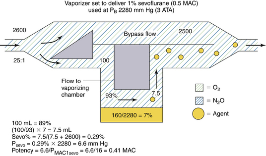
FIGURE 3-15 Use of a concentration-calibrated variable bypass sevoflurane vaporizer under hyperbaric conditions. ATA, absolute atmospheric pressure; MAC, minimum alveolar concentration; PB, barometric pressure; PMAC1, partial pressure of a potent inhaled agent at a concentration of 1 MAC.
In the vaporizing chamber, the SVP of sevoflurane is 160 mm Hg and the sevoflurane concentration is 7% by volume (160/2280). A variable bypass sevoflurane vaporizer set to deliver 1% creates a splitting ratio of 25:1 for the fresh gas inflow. If the total gas flow to the vaporizer is 2600 mL/min, 100 mL of carrier gas enters the vaporizing chamber per minute (see Fig. 3-15). This 100 mL represents 93% of the atmosphere there (100% − 7%); the remainder is sevoflurane vapor. The amount of sevoflurane vapor evolved is [100/93] × 7, or 7.5 mL/min. This 7.5 mL is diluted to a total volume of 2607.5 mL (2500 + 100 + 7.5), giving 0.29% (7.5/2607.5) sevoflurane vapor by volume. This is 0.29 (0.29/1) times the vaporizer dial setting in terms of volumes percent.
What about potency? The partial pressure of sevoflurane in the emerging gas mixture is 6.6 mm Hg (0.29% × 2280 mm Hg). Dividing by the PMAC1 for sevoflurane of 16 mm Hg gives a potency output of 0.41 MAC (6.6/16). Thus a variable bypass sevoflurane vaporizer set to deliver 1% (0.5 MAC under conditions of 1 atm 760 mm Hg) delivers 0.41 MAC at 3 atm, or approximately 0.8 times the anesthetic potency expected (see Fig. 3-15).
To summarize, when used at atmospheric pressures greater than 760 mm Hg (sea level), a variable bypass vaporizer output concentration that is less than that set on the dial in volumes percent, but potency decreases by a lesser amount.
These examples show that although changing ambient pressure affects the output of a variable bypass vaporizer to a significant degree in terms of volumes percent, the effect on anesthetic potency (i.e., MAC multiple) is less dramatic. In the examples discussed, it was assumed that ambient pressure has a negligible effect on SVP. It is also assumed that the set splitting ratios remain constant as ambient pressure changes. In reality, however, changes in gas density occur with changes in ambient pressure and may affect the splitting ratios slightly (see Appendix). From a clinical point of view, however, the anesthetic potency output expected for any given vaporizer dial setting changes little, even though vapor concentration (vol/vol) may be altered considerably. Again, it must be emphasized that vaporizer output concentration expressed in volumes percent is of limited value unless converted to an MAC multiple according to the concept of MAPP, as previously described.
Vaporizing Chamber Flow Controlled at Outlet
The potency output of a variable bypass vaporizer in which the vaporizing chamber gas flow is controlled by a variable orifice located at the vaporizing chamber outlet is unaffected by changes in barometric pressure. With this design, the exit split ratio will apply and is unchanged. Consider the design of a vaporizer used to create 1% sevoflurane. In Figure 3-8, the exit split ratio to create 1% sevoflurane is 20:1. Under the same hypobaric conditions as in the previous section, PB is 500 mm Hg. In the vaporizing chamber, the sevoflurane vapor concentration is 160/500 = 32% by volume. A flow of 100 mL/min of 32% sevoflurane is mixed with a bypass flow of 2000 mL/min; the sevoflurane concentration will be 32/2100 = 1.52% by volume. The partial pressure of sevoflurane will be 1.52% × 500 = 7.6 mm Hg, which is the same partial pressure/potency as 1% sevoflurane at 760 mm Hg.
Under hyperbaric conditions of 2280 mm Hg, in the vaporizing chamber the sevoflurane vapor concentration is 160/2280 = 7% by volume. A flow of 100 mL/min of 7% sevoflurane is mixed with a bypass flow of 2000 mL/min. The sevoflurane concentration will be 7/2100 = 0.33% by volume.
Arrangement of Vaporizers
Very old, now-obsolete models of anesthesia machines had up to three variable bypass vaporizers arranged in series, making it possible for carrier gas to pass through each vaporizer, albeit all through a bypass chamber, to reach the common gas outlet of the anesthesia machine. Without an interlock system, which permits only one vaporizer to be in use at any one time, it was possible to have all three vaporizers turned on simultaneously. Apart from potentially delivering an anesthetic overdose to the patient, the agent from the upstream vaporizer could contaminate agents in any downstream vaporizer.16 During subsequent use, the output of any downstream vaporizer would be contaminated. The resulting concentrations in the emerging gas and vapor mixture would be indeterminate and possibly lethal.
When such a serial arrangement of vaporizers was present, it was important to ensure that a vaporizer designed for a less volatile agent—such as methoxyflurane, with a low SVP—was not placed downstream relative to more volatile anesthetics, such as halothane. In such a case, halothane upstream would dissolve in the less volatile agent downstream. If during subsequent use the methoxyflurane vaporizer were set to deliver 1% (6 MAC), more than 6% halothane (8 MAC) could have been delivered from the methoxyflurane vaporizer.19 The most desirable serial sequence of vaporizers from flowmeter manifold to common gas outlet was therefore methoxyflurane, sevoflurane, enflurane, isoflurane, then halothane.
These principles would also apply if a freestanding vaporizer were to be placed in series between the machine common gas outlet and the breathing circuit. Such arrangements, configured by the user and never by the machine manufacturer, are potentially dangerous and should not be used.20 In addition to the contamination problem by agents upstream, such vaporizers are more easily tipped over, and use of the machine oxygen flush with the freestanding vaporizer turned on could pump a bolus of agent into the patient circuit, while disconnection of the vaporizer tubing could result in hypoxia in the patient circuit (see Chapter 30). Nevertheless, freestanding vaporizers are routinely used in conjunction with pump oxygenators for cardiopulmonary bypass. In such situations, the vaporizer should be securely mounted to the pump (see Fig. 3-16), and correct directional flow of gas through the vaporizer must be confirmed. Such vaporizers are subject to the same routine maintenance and calibration procedures as are all other anesthesia vaporizers.
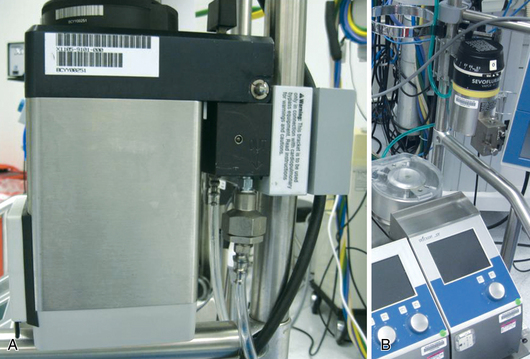
FIGURE 3-16 Freestanding vaporizer mounted on a pump oxygenator. Note the warning label on the mounting bracket in A, which reads, “This bracket is to be used only in conjunction with cardiopulmonary bypass equipment. Read instructions for warnings and caution.”
With contemporary anesthesia workstations, only one vaporizer can be on at any given time. To prevent cross-contamination of the contents of one vaporizer with those of another, the ASTM standards require that a system be in place to isolate the vaporizers from one another and prevent gas from passing through more than one vaporizing chamber.3 This specification is met by an interlock system. All contemporary anesthesia workstations incorporate manufacturer-specific interlock/vaporizer exclusion systems; these are described in subsequent sections concerning specific vaporizer models.
Calibration and Checking of Vaporizer Outputs
Vaporizers should be serviced according to the manufacturer’s instructions, and their output should be checked to ensure that no malfunction exists. The vaporizer dial is set to deliver a certain concentration of the agent; the actual output concentration is measured by a calibrated anesthetic agent analyzer that analyzes gas sampled at the common gas outlet of the anesthesia machine. Currently available methods for practical vapor analysis are described in Chapter 8.
Preparation of a Standard Vapor Concentration
Although the physical methods for measurement described in Chapter 8 may be used to check vaporizer output, the agent analyzers themselves require calibration. For this purpose, standard vapor concentrations must be prepared and made available for use as the calibration gas standards. Standard mixtures are available from commercial suppliers.
Consider the preparation of a standard mixture of isoflurane in oxygen. Avogadro’s volume states that 1 g molecular weight of a gas or vapor will occupy 22.4 L at standard temperature and pressure (STP, which is 760 mm Hg pressure, 0° C, or 273 K). Because the molecular weight of isoflurane is 184.5 Da, it would occupy 22.4 L at STP, and 1 g would occupy 22.4/184.5 L.
Charles’ law states that the volume of a fixed mass of gas is proportional to absolute temperature if pressure remains constant; therefore 1 g of isoflurane occupies 0.13 L ([22.4 L/184.5 g] × [293 K/273 K]) at 20° C, or 293 K). One milliliter of liquid isoflurane weighs 1.5 g (specific gravity of 1.5; see Table 3-2); 1 mL of liquid isoflurane therefore generates 0.195 L of vapor ([22.4/184.5] × [293/273] × 1.5). Thus, 1 mL of liquid isoflurane produces 195 mL of vapor at 20° C.
By this type of calculation, a predetermined volume of liquid agent can be measured accurately and vaporized in a chamber of known volume to produce a calibration-standard gas mixture. As previously discussed, if a vaporizer is tipped on its side and liquid agent enters the bypass chamber or fresh gas piping, small volumes of liquid agent can generate very large volumes of vapor.
The above calculation by which volumes of liquid agent can be related to volumes of vapor at known temperatures and ambient pressures can be used to calculate the cost of an inhaled anesthetic. For example, an anesthetic of 1% isoflurane in 2 L/min N2O and 1 L/min O2 requires delivery of 30 mL/min (1% × 3 L), or 1800 mL/h of isoflurane vapor. This can be expressed as 1800/195, or 9.23 mL/h of liquid isoflurane. If, for example, a 100-mL bottle of isoflurane costs $10, the isoflurane anesthetic cost would be $0.92/h ([9.23/100] × $10).
Effect of Use Variables on Vaporizer Function
The output of a concentration-calibrated vaporizer is normally a function of fresh gas inflow rate. Because 1 mL of liquid agent produces approximately 200 mL of vapor, the hourly consumption of liquid agent can be estimated by the following formula:
The derivation of this approximation is as follows:


Hence, the factor of 3 is used in the formula. Thus an isoflurane vaporizer set to deliver 1.5% at a flow rate of 4 L/min consumes approximately 18 mL/h (3 × 1.5 × 4) of liquid agent.
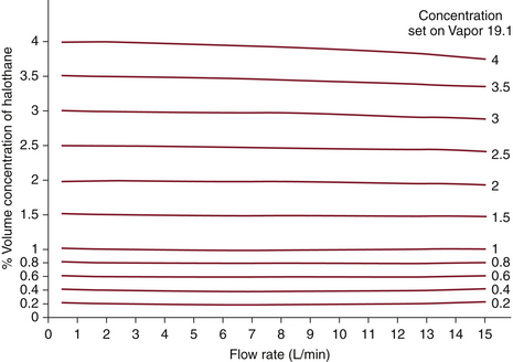
The output concentrations of contemporary concentration-calibrated vaporizers are virtually independent of the fresh gas flow rate when used with flows and vaporizer settings in the normal clinical range. At high concentration settings and with high fresh gas flows, output is slightly less than that set on the dial. Under these conditions, evaporation of the agent may be incomplete and temperature in the vaporizing chamber will fall. Thus, saturation of gas flowing through the vaporizing chamber is incomplete and output falls. The effects of flow rate on vaporizer output are shown for the Dräger Vapor 19.1 (Fig. 3-17). Again, note that these effects are of little clinical significance in most situations.
Fresh Gas Composition
As previously noted, changing the composition of the carrier gas, especially by adding or removing nitrous oxide, temporarily alters vaporizer output.17 In the case of nitrous oxide, this effect is mainly due to solubility of nitrous oxide, although changes in gas density and viscosity also contribute to changes in output by affecting the flow split between vaporizing chamber and bypass gas flows.
GE vaporizers are calibrated using 100% oxygen as the carrier gas.18 If the carrier gas is changed to air or nitrous oxide, the vapor output decreases at low flow rates. At high flow rates and low concentration dial settings, the output may increase slightly.
Dräger Vapor 19.n vaporizers are calibrated with air as the carrier gas.12 If 100% oxygen is used, the delivered output concentration is approximately 5% to 10% greater than the dial setting (air calibration value). When a mixture of nitrous oxide and oxygen (70:30) is used, the output is 5% to 10% lower than the dial setting. In this model of vaporizer, deviations from the dial setting increase with lower fresh gas flows, small amounts of agent in the vaporizing chamber, higher concentration dial settings, and extreme changes in the composition of the carrier gas.11
Effects of Temperature
As previously described, concentration-calibrated vaporizers are temperature compensated. The effects of changes in temperature are negligible under usual conditions of use. However, if the ambient temperature exceeds the vaporizer’s specified range of performance, the vaporizer’s output may become high. For example, the Dräger Vapor 19.n vaporizer is specified as accurate between 15° C and 35° C.12 This is because as temperature increases, the vapor pressure of the anesthetic increases in a nonlinear manner, whereas the temperature compensation is linear. Indeed, the output may become unpredictable and uncontrolled if the boiling point of the agent is reached. Conversely, if the temperature falls below the specified range for use, the output may be unpredictably low.
Fluctuating Backpressure
A problem with older model vaporizers was that fluctuating or intermittent backpressure, the so-called pumping effect, may be applied to the vaporizer by changes in pressure downstream. Such pressure changes could be caused by intermittent positive-pressure ventilation (IPPV) in the patient circuit or operation of the oxygen flush control. These changes could produce changes in gas flow distribution within the vaporizer, which could lead to increased output if no compensatory mechanism existed. The effects of intermittent pressurization are greatest at low flow rates, low concentration settings, when small amounts of liquid agent are present in the vaporizer, and with large and rapid changes in pressure. Higher flow rates, higher dial settings, larger volumes of liquid agent in the vaporizer, and smaller, less frequent changes in pressure minimize the pumping effect.
Of the several explanations offered for the pumping effect, the most probable is that during pressurization, gas is compressed in the vaporizer in both the vaporizing chamber and the bypass. When the pressure decreases, anesthetic vapor leaves the vaporizing chamber, through both the normal exit pathway and the vaporizing chamber inlet, to enter the bypass flow. The intermittent addition of vapor to the bypass flow results in the observed intermittent increase in vaporizer output.
Contemporary vaporizers incorporate certain design features that minimize the significance of the pumping effect (discussed in the following section). Some older models, such as the Ohio Medical calibrated vaporizers, have a check valve in the vaporizer outlet to prevent transmission of increases in downstream pressure (see Fig. 3-11).8 Certain models of GE anesthesia machines use a check valve just upstream of the common gas outlet to prevent retrograde transmission of downstream pressures (see Chapter 2). However, while the check valve is closed, the pressure upstream of it—and hence, that in the vaporizers—increases because of continuous fresh gas flow from the machine flowmeters. Thus the use of check valves can limit, but not totally eliminate, the pumping effect. For this reason, the newest anesthesia machine models do not use check valves in their design (see Chapter 2).
Contemporary Vaporizers
The Dräger Vapor 19.n vaporizer is used on many contemporary Draeger Medical anesthesia workstations (Fig. 3-18). Up to three such vaporizers may be mounted on the back bar of the workstation and are connected to an interlock system designed to ensure that only one vaporizer or agent is in use at any time. When one vaporizer is turned on, the dials on the others cannot be turned from zero. Because failures have been reported,21 the interlock system’s function must be checked periodically (see Chapter 30).
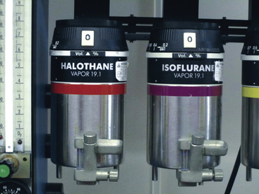
FIGURE 3-18 Dräger Vapor 19.1 vaporizers (Dräger Medical, Telford, PA). Note the funnel-fill design, which has been superseded by an agent-specific key-fill design.
A schematic of the Dräger Vapor 19.1 vaporizer is shown in Figure 3-19.11 Its operation is fairly straightforward. With the concentration knob in the zero position, the on/off switch is closed. Fresh gas enters the vaporizer at the fresh gas inlet and leaves via the fresh gas outlet without entering the vaporizing parts of the unit. In this off state, the inlet and outlet ports of the vaporizing chamber are connected and vented to the atmosphere by a hole. The venting prevents pressure buildup in the vaporizing chamber, thereby preventing vapor from being driven under pressure into the fresh gas flow. Dräger specifies that venting results in a loss of only 0.5 mL/day of anesthetic into the operating room atmosphere at a temperature of 22° C. The vaporizer can be filled only in the off state.11
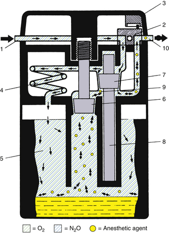
FIGURE 3-19 Schematic of Dräger Vapor 19.1 vaporizer. 1, Fresh gas inlet; 2, ON/OFF switch; 3, concentration dial; 4, pressure compensator; 5, vaporizing chamber; 6, control cone; 7, bypass cone; 8, expansion element; 9, mixing chamber; 10, fresh gas outlet. See text for details of operation. (Courtesy Dräger Medical, Telford, PA.)
When the concentration knob is turned to any concentration above 0.2 vol%, the on/off switch opens automatically, allowing the fresh gas to enter the interior of the vaporizer. The gas is immediately divided and follows two different routes: part of the fresh gas moves through a thermostatically controlled bypass, which compensates for temperature changes and maintains the correct volumes percent output as selected by the concentration knob. The remaining fresh gas moves through a pressure compensator, which prevents pressure changes that arise either upstream or downstream from being transmitted into the vaporizer and affecting the vapor output. From the pressure compensator, the gas continues into the vaporizing chamber, which contains the liquid anesthetic agent that is absorbed and evaporated by a special wick assembly. As the fresh gas moves through the vaporizing chamber, it becomes fully saturated with anesthetic vapor. The saturated gas leaves the chamber through a control cone, which is adjustable using the concentration knob. The saturated vapor and the fresh gas that did not pass through the vaporizing chamber are combined and leave through the fresh gas outlet. The combination of the bypass opening and the control cone opening determines the volumes percent of the vapor output. The output of this vaporizer is unaffected by changes in barometric pressure.
In this vaporizer, the pumping effect is prevented by the design of the long, spiral inlet tube, the pressure compensator. When the vaporizing chamber becomes decompressed, some anesthetic vapor does enter this spiral, but because of the spiral’s length, the vapor does not reach the bypass gas flow.
Temperature compensation is achieved by the bypass cone and the expansion element. When temperature rises, bypass flow increases. Sudden changes in temperature require a compensation time of 6 min/° C for concentration output to be maintained within specifications.11
In the past, the Dräger Vapor 19.1 was available with either a funnel-type or an agent-specific filling device even though overfilling was not possible because the liquid level was limited by the position of the filling mechanism. The capacity of the vaporizing chamber is approximately 200 mL with dry wicks and 140 mL with wet wicks. This vaporizer does not include an antispill mechanism and should not be tilted more than 45 degrees. If tilted more than this, it should be flushed with a gas flow of 10 L/min with the concentration dial set to maximum before clinical use, similar to when the vaporizer has been tipped. Dräger states that a flushing time of 5 minutes is usually adequate if the vaporizer has been tilted only briefly and then immediately righted. If it has been tilted for a longer time, a minimum flush period of 20 minutes is required, during which it is advisable to drain liquid anesthetic from the vaporizing chamber.11 The manufacturer stipulates that the vaporizer should be inspected and serviced every 6 months by qualified personnel and that an official maintenance record be kept.11
Whether in the off or on position, the Dräger 19.1 vaporizer is designed to limit the pressure of the fresh gas supply to a maximum of approximately 18 psig. Thus, if the anesthesia machine’s common gas outlet becomes occluded and the oxygen flush is operated, a pressure of 45 to 55 psig could be transmitted retrograde from the common gas outlet back to the flowmeters if not relieved through the vaporizer. When more than one vaporizer is present (up to three are possible), pressure relief usually occurs through the one closest to the common gas outlet. Thus, even when the vaporizer is turned off, fresh gas continues to flow through the vaporizer unit, albeit not to the vaporizing sections, and is therefore subject to the pressure-limiting mechanism described above.
Dräger Vapor 2000
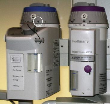
The Dräger Vapor 2000 uses the same operating principles as the Vapor 19.1, but it incorporates a number of improvements (Fig. 3-20). The sump has an increased capacity (300 mL) for liquid agent. In the United States, the Vapor 19.n vaporizers are bolted to Dräger machines and are not intended to be removed by the anesthesia caregiver. This is to prevent the problems associated with a vaporizer being tipped more than 45 degrees. If the vaporizer is to be transported, it first must be drained of any agent. The Vapor 2000 is designed so that no emptying is required before transportation, and the unit can be removed by the anesthesia caregiver. The spill-proof design ensures that even violent shaking cannot cause any liquid anesthetic to enter the concentration control elements or the atmosphere. To remove a Vapor 2000 from its mount on the machine, the control dial must first be turned to the T position, or transport mode, in which the vaporizer sump is isolated from the rest of the vaporizer (Fig. 3-20). The Vapor 2000 has an extended temperature range (15° C to 40° C) compared with 15° C to 35° C for the Vapor 19.n. The Vapor 2000 can be mounted on the Dräger plug-in system or the GE Select-a-tec system.
Tec 5
The Tec 5 vaporizer is used on recent GE Healthcare Datex-Ohmeda anesthesia machines (see Fig. 3-21).18 Up to three vaporizers may be mounted and locked on a special, patented Selectatec manifold.
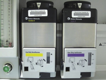
Each Tec 5 vaporizer is locked to the manifold by a Select-a-tec locking lever. Unless this lever is in the locked position, the concentration control dial release cannot be activated (Fig. 3-22). Once the lever is in the locked position, the dial release can be depressed. This operates the vaporizer interlock mechanism, which causes the interlock extension rods to extend laterally to adjacent vaporizers, minimizing the possibility of them being turned on. Simultaneously, the two Select-a-tec port valve actuating spindles are activated to allow fresh gas to enter the vaporizer. Depressing the control dial release button also enables the control dial to be turned to the desired vapor output concentration. When the control dial is turned off and the dial release is no longer depressed, the manifold port valves close and the extension rods are retracted to allow selection of another vaporizer. Thus, in the Select-a-tec system, fresh gas enters a vaporizer only when the vaporizer is turned on; otherwise, fresh gas bypasses the vaporizer(s) via a separate channel in the manifold (Fig. 3-23).
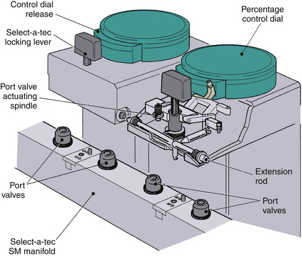
FIGURE 3-22 GE Datex-Ohmeda Select-a-tec vaporizer interlock system. SM, series-mounted manifold. (Courtesy GE Healthcare, Waukesha, WI.)
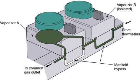
FIGURE 3-23 GE Datex-Ohmeda series-mounted manifold gas circuit. Fresh gas from the machine flowmeters enters the manifolds, which incorporate pairs of series-connected, two-way port valves. When a Tec 5 vaporizer is locked onto the manifold and turned on (vaporizer A), both associated port valves are opened. Fresh gas from the manifold then flows into the vaporizer through the inlet port valves, and the gas-agent mixture exits via the outlet port valve. When the vaporizer is turned off (vaporizer B), or if no vaporizer is fitted to the manifold, each port valve is closed to allow gas to bypass the vaporizer via the manifold bypass circuit. (Courtesy GE Healthcare, Waukesha, WI.)
Figure 3-24, A, shows a Tec 5 vaporizer flow diagram, and Figure 3-24, B, shows a schematic of the Tec 5. When the concentration dial is set in the zero position, all gas passages are closed except for a channel linking the vaporizer inlet and outlet. As shown in Figure 3-24, B, when the dial is turned past 0%, the carrier gas stream is split between bypass and vaporizing chamber flows. Bypass gas flows vertically downward from a, across the base of the sump, through the thermostat to c, and back up the gas transfer manifold via d to e. The thermostat or temperature-compensating device is located in the base of the vaporizer. It is a bimetallic strip design, which increases bypass flow as temperature rises and decreases bypass flow as temperature falls.
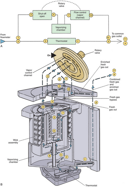
FIGURE 3-24 A, GE Datex-Ohmeda Tec 5 vaporizer flow diagram. B, Schematic of Tec 5 vaporizer. Gas flow enters the vaporizer (1) and is split into two streams: the bypass circuit and the vaporizing chamber. Gas flows downward through the bypass circuit from a, across the sump base b, through the thermostat to c, and back up the gas transfer manifold via d to e. Gas flowing to the vaporizing chamber flows from 1 across the sump cover (2), where it is diverted via 3 through the central cavity of the rotary valve and back through the intermittent positive pressure ventilation (IPPV) assembly via 4, 5, and 6. Gas then flows from the IPPV assembly via 7 down the tubular wick assembly, where vapor is added; it then flows across the base of the vaporizing chamber above the liquid agent to 8. From here the gas-vapor mixture flows via 9 through the sump cover to the proportional radial drug control groove of the rotary valve and back into the sump cover (10), where it merges with gas from the bypass circuit. The total flow then exits the vaporizer into the outlet port of the Select-a-tec manifold. (Courtesy GE Healthcare, Waukesha, WI.)
The Tec 5 incorporates an IPPV chamber to minimize the pumping effect. The fresh gas flowing to the vaporizing chamber flows through an IPPV assembly designed to minimize the pumping effect before it reaches the vaporizing chamber and wick assembly system. There the gas becomes saturated with anesthetic vapor and flows onward to combine with the bypass gas flow and exit the vaporizer.
In the Tec 5 vaporizer, temperature compensation is achieved by a bimetallic strip valve rather than a bypass cone and expansion element. The vaporizer incorporates a keyed fill system, but some older models may still have a funnel-fill design. Although the Tec 5 incorporates an antispill mechanism, if the vaporizer is inverted, it is recommended that it be purged with carrier gas at 5 L/min for 30 minutes with the dial set to 5%.18
The Tec 5 vaporizer has a liquid agent capacity of 300 mL with dry wicks and 225 mL with wet wicks. The vaporizer is calibrated at 22° C with oxygen at 5 L/min. As previously discussed, changes in carrier gas composition may affect agent output concentration.
The operator’s manual recommends that the vaporizer be serviced every 3 years at an authorized service center.18 Service should include complete disassembly; thorough cleaning; inspection for wear and damage; renewal of wicks, seals, and any worn components; replacement of discontinued parts with more current parts; checking of output; and recalibration if necessary.
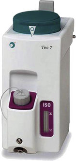
Tec 7
The Tec 7 (see Fig. 3-25) is essentially the same as the Tec 5 (see Fig. 3-21) but has an improved ergonomic design, a 300-mL capacity for liquid agent, and an improved nonspill system to protect internal components if the vaporizer is moved or tilted and it does not require scheduled factory service.
Limitations of Earlier Selectatec Systems
As previously discussed, the Select-a-tec vaporizer extension system relies on vaporizers being adjacent to one another so that extrusion of the extension rods of one vaporizer prevents the other from being turned on. In earlier designs, the Select-a-tec system could be defeated. Thus, if the middle of the three vaporizers was removed, the remaining two, now nonadjacent, could both be turned on. In such a situation, one of the two outer vaporizers should be moved to the center position so that the vaporizers are adjacent. However, Select-a-tec systems manufactured after 1987 are designed so that when the middle vaporizer is removed, extrusion of the lateral rod of one vaporizer is transmitted to the other via vertical plates joined by a communicating bar. With this Select-a-tec system, the vaporizer interlock is therefore effective even if the center vaporizer is removed.
Desflurane Vaporizers
Desflurane (Suprane, Baxter Health Care Products, Deerfield, IL) is a potent, inhaled, volatile anesthetic approved for use by the U.S. Food and Drug Administration (FDA) in 1992. The physical properties differ considerably from those of other agents in clinical use (see Table 3-2). With an SVP of 669 mm Hg at 20° C and a boiling point of 22.8° C at 1 atm, this agent is extremely volatile, which presents certain problems when it comes to vaporization and production of controlled concentrations of vapor. This agent clearly cannot be administered with the conventional mechanical variable bypass vaporizer design used for halothane, enflurane, isoflurane, and sevoflurane. If a variable bypass vaporizer were somehow filled with desflurane, an increase in temperature to above 22.8° C would result in the desflurane boiling in the vaporizing chamber and would lead to uncontrolled output of desflurane vapor from the vaporizer. The consequences of misfilling contemporary agent-specific variable bypass vaporizers with desflurane at 22° C have been predicted.22 Thus, at 22° C, an enflurane vaporizer set to deliver 3 MAC (~5%) enflurane would deliver 16 MAC (~96%) desflurane.
The Tec 6 concentration-calibrated vaporizer was specifically developed for the controlled administration of desflurane (Fig. 3-26). It was designed to make the practical aspect of the clinical administration of desflurane no different from that of other potent inhaled agents with the Tec series of vaporizers. The principle of operation of the Tec 6 is that liquid desflurane is heated in a chamber, or sump, to 39° C to produce vapor under pressure (~1500 mm Hg, or 2 atm absolute pressure). As Figure 3-27 illustrates, this is analogous to having a reservoir of compressed gas in a tank. The vapor leaves the sump via a variable pressure–regulating valve, the opening of which is continuously adjusted based on the output from a pressure transducer to ensure that the pressure of the desflurane vapor entering the rotary valve in the user-controlled concentration dial is the same as the backpressure generated by the fresh gas inflow from the anesthesia machine flowmeters into a fixed restrictor. The concentration dial and rotary valve control the quantity of desflurane vapor added to the fresh gas flow so that what emerges from the vaporizer outlet is the dialed-in concentration of desflurane. In the Tec 6, unlike other concentration-calibrated vaporizers, no fresh gas enters the desflurane sump. In addition, the Tec 6 is calibrated by the manufacturer with 100% oxygen as the fresh gas.
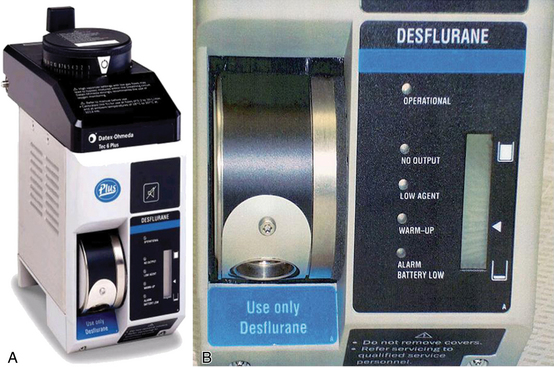
FIGURE 3-26 A, GE Healthcare (Waukesha, WI) Tec 6 vaporizer for desflurane. B, Close-up of front panel shows status lights and display for agent fill status.
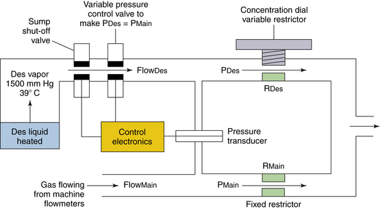
FIGURE 3-27 Simplified schematic of the Datex-Ohmeda Tec 6 vaporizer (GE Healthcare, Waukesha, WI). Liquid desflurane (Des) is heated in the sump to 39° C to produce vapor under pressure (~1500 mm Hg). The variable pressure control valve is continuously adjusted by an output from the differential pressure transducer to ensure that the pressure of the desflurane vapor upstream of the rotary valve (concentration dial variable restrictor) is the same as the pressure of the fresh gas inflow to the fixed restrictor. The concentration dial and rotary valve control the quantity of desflurane vapor added to the fresh gas flow so that what emerges from the vaporizer outlet is the dialed-in concentration of desflurane. No fresh gas enters the desflurane vaporizing chamber; this is in contrast to the other Tec series vaporizers, which are of the variable bypass design. FlowDes, flow of desflurane vapor; FlowMain, gas flow from the machine flowmeters (O2, N2O, air); PDes, pressure of desflurane vapor flowing into concentration dial variable restrictor; PMain, pressure of gas flowing into fixed restrictor; RDes, resistance to flow of desflurane created by variable restrictor; RMain, resistance of fixed restrictor.
As the oxygen enters the vaporizer, it flows through a fixed restrictor (see Fig. 3-27). This is a device that offers a fixed resistance, defined as change in pressure per unit of flow. The resistance is approximately 10 cm H2O/L/min over a wide range of gas flows. The backpressure created by gas flowing through the fixed restrictor is therefore proportional to the main gas flow as set on the machine flowmeters; this backpressure changes according to Poiseuille’s law for laminar flow:

where π is 3.142, P is the pressure difference across the resistor, r is the radius of the resistor, η is the viscosity of the gas flowing, and L is the length of the resistor. That is, flow is directly proportional to pressure. By sensing this backpressure via a pressure transducer and ensuring that the pressure of the desflurane vapor entering the variable restrictor is always made equal to this pressure via the control electronics and variable pressure control valve, the variable restrictor provides a means to control the concentration of desflurane (Figs. 3-27 and 3-28). Thus,
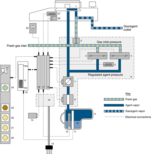
FIGURE 3-28 Detailed schematic of the GE Datex-Ohmeda Tec 6 desflurane vaporizer.1, Concentration dial and rotary valve; 2, fixed restrictor; 3, pressure transducer; 4, pressure monitor; 5, heater to prevent condensation of desflurane; 6, vapor control manifold assembly; 7, pressure regulating valve; 8, shut-off valve; 9, sump assembly; 10, liquid desflurane; 11, level sensor; 12, sump heater to heat desflurane to 39° C; 13, power cord; 14, backup battery for alarms; 15, power supply; 16, control electronics printed circuit board; 17, heater electronics; 18, alarm electronics circuit board; 19, liquid crystal sump agent level display; 20, “alarm battery low” light-emitting diode (LED); 21, “warm up/operational” LED; 22, “low agent” warning LED; 23, “no output” warning LED; 24, “operational” LED; 25, tilt switch (shuts down vaporizer if tilted excessively); 26, solenoid dial lock; 27, heater to prevent condensation of desflurane in valve plate (From Ohmeda Tec 6 vaporizer operation and maintenance manual. Madison, WI, 1992. Courtesy GE Healthcare, Waukesha, WI.)
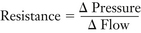 (3-1)
(3-1)
For the main gas flow of oxygen entering the fixed restrictor,
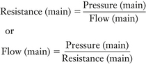 (3-2)
(3-2)
But Resistance (main) is a fixed resistor and is therefore constant (K in equation 3-4, or 10 cm H2O per L/min), so Flow (main) ∝ Pressure (main).
For the desflurane flow entering the concentration dial variable restrictor,
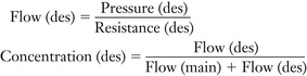 (3-3)
(3-3)
If Flow (des) is low compared with Flow (main), Flow (des) in the denominator of equation 3-1 can be ignored; thus,
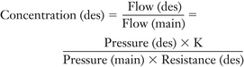 (3-4)
(3-4)
The pressure transducer, control electronics, and variable pressure control valve ensure that Pressure (des) = Pressure (main); therefore,
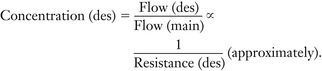 (3-5)
(3-5)
Thus, it becomes apparent that the variable restrictor in the concentration dial—that is, the resistance to the flow of desflurane—can be calibrated in terms of desflurane concentration. The calibration of the variable restrictor is not linear, however; equation 3-3 above is only an approximation because the Flow (des) value in the denominator of equation 3-3 cannot always be ignored.
Some examples of vaporizer concentration dial and gas flow settings are presented to illustrate the application of these principles.
Examples of Vaporizer Concentration Settings
Consider a Tec 6 vaporizer set to deliver 10% desflurane at a fresh gas flow of 5 L/min O2
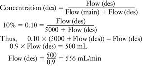 (3-6)
(3-6)
Thus, at a 5 L/min flow of O2 set to deliver 10% desflurane, the Tec 6 adds 556 mL/min of desflurane vapor to the main gas flow; in effect,
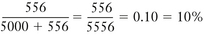 (3-7)
(3-7)
Once the main flow, in this case 5 L/min O2, and the desflurane flow (calculated as above) are known, the ratio of resistances of the variable resistor, Resistance (des) in the concentration dial, to the fixed resistor, Resistance (main) in the main gas flow, may be calculated. Thus,
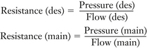 (3-8)
(3-8)
But, Pressure (des) = Pressure (main); therefore,
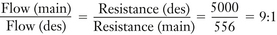 (3-9)
(3-9)
Resistance (des) may also be calculated as follows:
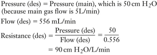 (3-10)
Now increase fresh gas flow to 10 L/min. Increasing Flow (main) from 5 L/min to 10 L/min causes a temporary imbalance of pressures across the differential pressure transducer because Pressure (main) increases from 50 to 100 cm H2O (see Figs. 3-27 and 3-28); bear in mind that Resistance (main) is 10 cm H2O/L/min. The pressure imbalance is sensed by the differential pressure transducer, and the control electronics cause the variable pressure control valve to open wider—that is, to decrease its resistance to desflurane vapor flowing from the sump at a pressure of 1500 mm Hg—so that the flow of desflurane vapor into the concentration dial variable restrictor increases until Pressure (des) is also 100 cm H2O. The increase in Flow (des) and thereby Pressure (des) ensures that the Tec 6 continues to deliver the 10% concentration as set on the dial.
Now increase the concentration dial setting from 10% to 15% while maintaining gas flow of 10 L/min. Increasing the concentration dial setting to 15% causes a decrease in Resistance (des). The resulting decrease in Pressure (des) relative to Pressure (main) is sensed by the differential pressure transducer, and the control electronics cause the variable pressure control valve to open wider—that is, to decrease its resistance to desflurane vapor flowing from the sump—so that Pressure (des) is increased to again be equal to Pressure (main). The resulting increase in Flow (des) ensures that the vapor concentration increases.
Now decrease the concentration dial setting from 15% to 5% at 10 L/min gas flow. Changing the concentration dial setting from 15% to 5% creates an increase in Resistance (des), which causes an increase in Pressure (des). The latter is sensed by the differential pressure transducer because Pressure (des) is now greater than Pressure (main), and the control electronics cause the variable pressure control valve to decrease its opening—that is, to increase its resistance to desflurane vapor flowing from the sump—thereby decreasing Flow (des) until Pressure (des) once again equals Pressure (main).
Special Considerations
Design Features of the Tec 6: The design of the Tec 6 is shown in Figures 3-26 and 3-27.23,24 The sump, when full, contains 450 mL of desflurane. Because the sump is pressurized to 1500 mm Hg, the agent level is sensed electronically and is shown on a liquid crystal display (LCD) rather than the sight glass used in variable bypass vaporizers. When the vaporizer is energized by connecting the power cord to an electrical outlet, a heater in the sump heats the agent to 39° C and maintains that temperature via thermostatic controls. While the agent is being heated, the sump shut-off valve is held closed, thus keeping the agent in the sump. The vaporizer is not operational during the warm-up period because the sump shut-off valve remains closed, and a solenoid locking device prevents the concentration dial from being turned to ON. Once operational (at 39° C), the dial lock is released and, when the dial is turned on, the sump shut-off valve is opened to permit desflurane vapor to flow to the pressure-regulating valve.
To prevent condensation, or “rain out,” of desflurane vapor, in addition to the heater in the sump, heaters in the rotary valve and in the vicinity of the pressure transducers, which sense the backpressures that result from the main gas flow and the flow of desflurane.
The Tec 6 thus differs considerably from mechanical variable bypass vaporizers; none of the fresh gas flow enters the vaporizing chamber. The Tec 6 requires electrical power and incorporates sophisticated electronics to ensure normal operations and a display panel to inform the user about its operational status. It also has alarms to alert personnel to any malfunction, in which case the sump shut-off valve closes.
Filling System: Because of its high SVP, desflurane is supplied in plastic-coated glass bottles to which an agent-specific filling device is firmly attached. The plastic coating provides an additional layer of protection if the glass bottle breaks or shatters. The vaporizer incorporates a patented, agent-specific filling system (SAF-T-FIL) that permits filling of the sump at any time, including when the vaporizer is in use. This may be important because of desflurane’s low blood-gas partition coefficient.
During filling, the bottle is locked to the vaporizer filling system and the high pressure of vapor in the sump at 39° C is transmitted to the interior of the bottle, which helps drive liquid desflurane from the bottle into the sump. When filling is complete, the bottle is disconnected from the vaporizer fill system and the valve on the bottle closes to avoid loss or spillage of agent. At this time the bottle contains vapor at 39° C and a pressure of 1500 mm Hg. As the bottle and its contents cool to room temperature, the pressure in the bottle decreases toward atmospheric pressure (760 mm Hg at 22.8° C).
Draining the Vaporizer: The Tec 6 can be drained before returning it for service, but a special draining kit is required and the accompanying instructions must be followed carefully. The manufacturer warns that failure to follow the instructions may result in rapid loss of pressure and/or agent, which could cause injury to personnel.24
Effect of Fresh Gas Composition on Performance: The Tec 6 is calibrated by the manufacturer with 100% O2. Performance accuracy at 5 L/min oxygen is specified as ±0.5% of delivered agent or ±15% of the dial setting, whichever is greater.24
From Poiseuille’s law, laminar flow through a resistor is determined as follows:
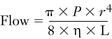 (3-11)
where π is 3.142, P is the pressure difference, r is the radius, η is viscosity, and L is length. Thus,
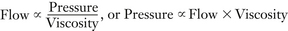 (3-12)
The Tec 6 design uses backpressure from gas flow through the fixed resistor to measure flow (see Fig. 3-27). If the viscosity of the gas flowing through the fixed resistor were to decrease, the same flow would result in a lower backpressure. This backpressure is used to determine the pressure of desflurane in the variable resistor in the concentration dial. A lower pressure results in a lower flow of desflurane vapor through the variable resistor.
Of the gases on the anesthesia machine, oxygen is the most viscous and nitrous oxide is the least viscous. Thus changing the main gas flow composition from oxygen to oxygen/nitrous oxide decreases gas viscosity; the output concentration of desflurane from that setting on the dial therefore decreases. Differences between the actual concentration produced and the dial setting are greatest, up to 20% of dial setting, with high concentrations of nitrous oxide at low gas flow rates. The clinical implications of this are minimal, however, because the anesthetic effect lost by the decrease in desflurane is offset by the anesthetic effect of the nitrous oxide.24,25
Effects of Changes in Altitude on Output: The Tec 6 accurately delivers the dialed-in concentration of desflurane in terms of volumes percent, even at altitudes other than sea level. At sea level, 7% desflurane (1 MAC) creates a desflurane partial pressure of 53 mm Hg (7% of 760 mm Hg, the PMAC1). At high altitude, if the ambient pressure were 500 mm Hg, the same 7% desflurane creates a desflurane partial pressure of only 35 mm Hg (7% of 500 mm Hg), which is only 0.66 of the PMAC1. To compensate for this decrease in potency output at increased altitude, a higher concentration (10.4%) must be set on the dial because 10.4% of 500 mm Hg renders a desflurane partial pressure of 52 mm Hg. Conversely, at higher ambient pressures, such as those at altitudes below sea level, a lower concentration dial setting would be indicated to create the same potency (MAC equivalent) output. Recommendations as to how the dial setting should be adjusted at various altitudes are provided in the operator’s manual.24
Interlock System: Although the Tec 6 is manufactured by GE Healthcare and is therefore mountable on a Selectatec manifold on a Datex-Ohmeda anesthesia machine, a version is also available for mounting on Dräger Medical workstations.
Tipping the Vaporizer: The Tec 6 incorporates a tilt switch. If the Tec 6 is tilted while in operational mode, the tilt switch activates an audible alarm, the sump shut-off valve closes (see Fig. 3-27), the vaporizer stops delivering vapor, and the red NO OUTPUT warning indicator flashes (see Fig. 3-26, B).
D-Vapor
The Dräger D-Vapor desflurane vaporizer by is an adjunct to the company’s Vapor 2000 series of vaporizers (Fig. 3-29).25 The operating principles are the same as those of the Tec 6, but the D-Vapor weighs significantly less. Similar to other vaporizers in the Vapor 2000 series, the D-Vapor is hermetically sealed when removed from an anesthesia system, allowing transport in any position, even when filled. The 300 mL reservoir capacity of the tank can hold the entire contents of a standard desflurane bottle. Like the Tec 6, the D-Vapor is electrically powered, but it also features 5 minutes of emergency battery operation to ensure that dose settings remain constant even during a brief power failure. Another difference is that the D-Vapor has a conventional sight glass to assess the level of liquid agent in the sump rather than the liquid crystal display of the Tec 6.
Penlon Sigma Alpha
Penlon Limited (Abingdon, United Kingdom) has also added a desflurane vaporizer, the Sigma Alpha, to their Sigma series of vaporizers (Fig. 3-30). The principle of operation differs from that of the Tec 6 and D-Vapor, however.
FIGURE 3-30 Penlon Sigma Alpha vaporizer for desflurane. (Courtesy Penlon, Abingdon, United Kingdom.)
Special Considerations
Operating Characteristics: The Alpha vaporizer operates by dosing a controlled flow of vaporized desflurane into the fresh gas. It achieves this by maintaining a constant vapor pressure in a small heated chamber and using that vapor pressure to drive the vapor through a microprocessor-controlled proportional valve into the fresh gas system.
Figure 3-31 shows the schematic of this vaporizer, which consists of a number of elements: the reservoir, heater assembly, dosing valves, control mechanism, and redundant backup monitor/control system.
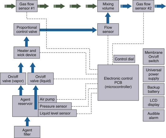
Startup: During switch-on and start-up procedures, the vaporizer control system performs a self-check of all internal systems and then calibraties the two fresh gas flow sensors and the backup vapor flow sensor. At this point the user can zero the “Agent Volume Used” display in preparation for logging if that information is required. The heater in the vaporizing chamber is turned on and brings the desflurane vapor chamber up to its operating temperature.
To provide a force to enable the liquid desflurane to be transferred from the reservoir to the heater assembly, a small mechanical pump is used to generate a pressure in the reservoir by pumping filtered room air into the reservoir. With fresh desflurane a small volume of air is dissolved into the desflurane; the reservoir pressure is therefore constantly monitored to ensure that the pressure is maintained at a minimum level to guarantee adequate pressure, and hence adequate desflurane delivery, at all times. In some operational environments, the temperature of the vaporizer in general ensures that the minimum pressure is achieved in the reservoir without assistance from the pump.
Agent Vaporization: When the vaporizer is required to deliver desflurane after the initial start-up period, the liquid on/off valve is opened, and liquid desflurane flows into the heater chamber and vaporizes rapidly, raising the pressure in the heater chamber to at least that of the reservoir pressure to prevent further delivery of liquid desflurane. If the vapor pressure in the heater chamber falls, more liquid desflurane is forced into the heater chamber from the reservoir, allowing more vaporization of the liquid desflurane and raising the pressure again. If pressure exceeds that in the reservoir, the pressure is vented back to the reservoir through the liquid desflurane delivery line, either as vapor or as a condensed liquid.
Once running, this pressure system is self-controlling because the heater chamber temperature, and hence vapor pressure, is kept constant.
Agent Delivery: When in use, the required desflurane concentration is set using the rotary control dial on the front of the vaporizer. The user selects a desired concentration, and the vaporizer inlet and outlet fresh gas flow sensors monitor the fresh gas flow and N2O concentration. The microprocessor then notes the pressure of the vaporized desflurane and the fresh gas flow rate and sets the calibrated delivery proportional valve to the correct opening to deliver the dialed-in desflurane concentration for that fresh gas flow. The vaporizer delivers desflurane vapor into the fresh gas flow at the required flow rate for the selected concentration, and a separate closed-loop control circuit measures the direct flow of desflurane to confirm correct desflurane vapor flows. Only the desflurane needed for vaporization is heated and maintained in a vapor form. The vapor pressure is automatically maintained because the vapor delivered into the fresh gas will be replaced by more vaporized liquid desflurane, and pressure will be maintained in the reservoir either by the excess pressure from the vapor chamber or by the external pump; this control system ensures a self-controlling and energy-efficient system.
Mixing Vaporized Agent into the Fresh Gas Supply: Fresh gas inlet and outlet flows are measured by flow-measuring devices. The gas flow sensors also detect the presence of nitrous oxide in the fresh gas supply and calculate the concentrations of oxygen and nitrous oxide. When desflurane is being delivered, the inlet and outlet flow sensors provide differential flow readings relative to the desflurane concentration irrespective of the fresh gas composition. This independent desflurane concentration measurement is used to provide a second redundant check for safe concentration delivery.
Vaporizer Filling: When the Penlon Sigma Alpha is used for desflurane administration, liquid desflurane is filled into the agent reservoir using a manufacturer-specific vaporizer filler connector design that is fully compatible with the standard desflurane closure and valve assembly attached to the SAF-T-FILL bottle top. The Alpha filler has no traditional sight glass but relies on a capacitive electronic level indicator to display the desflurane liquid level in the reservoir on the front panel display.
The vaporizer filler system contains several valves that open in sequence while the desflurane bottle is inserted and locked into the vaporizer filler by rotation of the vaporizer external filler knob. During the first part of the bottle insertion process, the bottle filler is sealed into the vaporizer filler with an O-ring seal, ensuring an airtight working environment. At this stage, the external filler knob is rotated clockwise and the bottle is drawn and locked into the vaporizer filler, opening the upper filling valve. Further rotation of the external filler knob will open the lower filling valve to the liquid chamber to allow the liquid desflurane to fill via the filling ports; an air return pathway allows a return of air to the emptying bottle. Toward the end of the rotation of the external filler knob, an air bleed valve opens briefly to equalize pressure throughout the filler and reservoir. Finally, on the last revolution of the external filler knob, the bottle valve is opened to allow liquid desflurane to flow into the vaporizer chamber.
When the desflurane liquid level in the reservoir is at its maximum, an air trap occurs in the air return (vapor return) line to the bottle and prevents further liquid desflurane being filled into the vaporizer in a manner similar to that of any traditional vaporizer filler system.
The bottle removal process is a reversal of the filling process. Note that by initially closing the bottle, the bottle and its internal volume, which may be under pressure, are isolated from the filler to minimize the spillage of desflurane vapor when the bottle is removed. The air bleed valve opens briefly again to break the air trap to ensure that pressures throughout the filler and reservoir are equalized. While both the upper and lower filling valves are still open, any liquid desflurane between the bottle and vaporizer filler drains from the bottle filler port and prevents leakage or pooling of desflurane above the vaporizer upper filling valve on final removal of the bottle. The upper and lower filling valves are closed just before the external filler knob reaches the bottle insertion/removal position.
Aladin Vaporizing System
Advances in technology and computerization of the workstation have led to development of the newly designed variable bypass, electrically powered Aladin vaporizing system used in the GE Datex-Ohmeda AS/3 Anesthesia Delivery Unit (ADU), Avance, and Aisys workstations (Fig. 3-32). The principles of operation differ from those of mechanical variable bypass vaporizers and from the Tec 6 design discussed above.
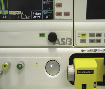
FIGURE 3-32 Aladin vaporizer system (GE Healthcare, Waukesha, WI) used on the AS/3 Anesthesia Delivery Unit and Aisys workstations.
The Aladin vaporizer consists of two separate parts that must be joined to produce a functioning vaporizer. One is a sump, the detachable Aladin cassette that holds up to 250 mL of liquid anesthetic agent. Each anesthetic agent, including desflurane, has its own cassette with a unique agent-specific filling system (e.g., SAF-T-FILL for desflurane and key fill or Quick-Fil [Abbott Laboratories, Abbott Park, IL] for other agents) (Figs. 3-32 to 3-34). Five different cassettes are available, one for each of the currently available potent inhaled agents. The second part of the vaporizer is an integral component of the anesthesia workstation and contains the concentration control hardware and software. The agent-specific cassette identifies itself to the workstation by the arrangement of signature magnets at the top of the cassette (Fig. 3-35, A). The Aladin system monitors and controls gas and vapor at several points and also regulates flow through the nitrous oxide, oxygen, and air flowmeters; it will not permit the delivered oxygen concentration to fall below 25% at the machine’s common gas outlet when nitrous oxide is in use. Gas flow from these sources is either delivered to or bypasses the anesthetic in the cassette. The flow issuing from the cassette and the bypass flows is monitored and adjusted by hardware and governed by software algorithms to produce the dialed-in concentration of anesthetic. The algorithms take into account the anesthetic agent, temperatures, and gas pressures in the cassette and bypass; each is separately measured.
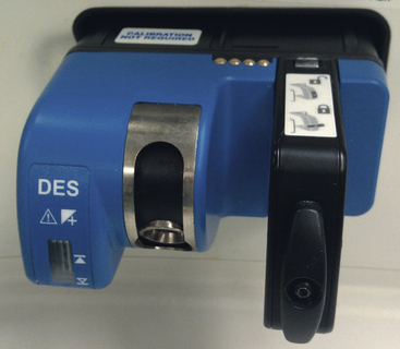
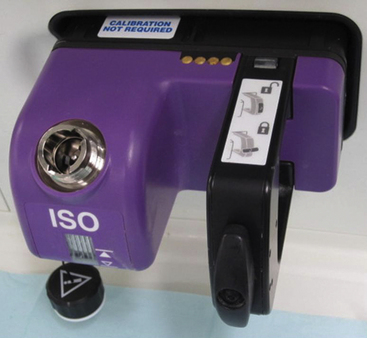
FIGURE 3-34 Aladin vaporizer system (GE Healthcare, Waukesha, WI) isoflurane cassette. The workstation recognizes the agent-specific cassette by the arrangement of identification (signature) magnets (see Fig. 3-35).
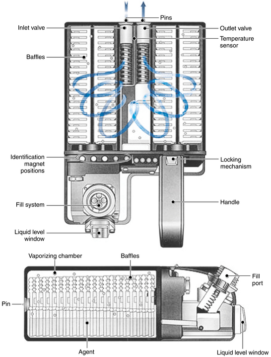
FIGURE 3-35 Schematic of Aladin vaporizer system cassette, which is the equivalent of the vaporizing chamber in a variable bypass vaporizer. Fresh gas flows over wicks and baffles containing liquid anesthetic agent. (Courtesy GE Healthcare, Waukesha, WI.)
Figures 3-35 and 3-36 show a schematic and principles of operation of the Aladin vaporizer.26 The agent wheel, an electronic control on the front panel of the ADU (see Fig. 3-32; or ComWheel on the front panel of the Aisys Carestation), is used to set the desired concentration of agent to be delivered to the breathing system. A green light-emitting diode (LED) indicates that the vaporizer is on. The vaporizer is controlled by a central processing unit (CPU), and the flow restrictor in the bypass causes fresh gas from the gas flow controls to be split into a bypass flow and a flow that passes through a unidirectional valve, which prevents backflow from the Aladin cassette. The latter is an agent-specific cartridge that contains liquid anesthetic at its SVC at the ambient temperature (e.g., ([160/760] × 100% = 21 volume percents for sevoflurane at 20° C). Continuous monitoring of temperature and pressure in the cassette means that the agent vapor concentration there is always known. The concentration of anesthetic vapor delivered to the common gas outlet of the machine is determined by the concentration of agent vapor in the cassette and the ratio of cassette outflow to the bypass flow, both of which are continuously measured. The delivered concentration is controlled by the position of the agent proportional valve (see Fig. 3-36), which is continuously set according to information from the agent controller (the CPU).
Each Aladin cassette is essentially a flow-over vaporizer because it contains liquid agent that is vaporized as fresh gas flows between the agent-soaked wicks and baffles (see Fig. 3-35). It is equivalent to the sump of a traditional variable bypass vaporizer, but because it does not incorporate bypass flow channels, tilting the cassette during handling, changing, or filling is not hazardous.
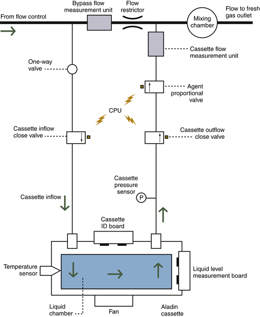
FIGURE 3-36 Schematic of Aladin vaporizer system to show principles of operation. CPU, central processing unit; ID, identification. (Courtesy GE Healthcare, Waukesha, WI.)
The Aladin cassette for desflurane (see Fig. 3-33) incorporates an electronic liquid level measuring device; if less than 10% liquid desflurane (<25 mL) remains, an alarm message is displayed. If the temperature is below 22.8° C, the boiling point of desflurane, fresh gas must enter the cassette for vapor to be delivered via the exit connection. If the temperature is above 22.8° C, no fresh gas inflow is needed and the desflurane vapor is released by controlling the outflow valve. A fan is mounted inside the fresh gas control unit beneath the Aladin cassette housing and is required to heat the cassette when large amounts of agent are being vaporized. The fan operates when the cassette temperature is below 17° C and stops when it rises above 20° C.
The Aladin vaporizing system offers certain advantages, the greatest of which is that the CPU can control the concentration of any of the potent inhaled anesthetic agents. Separate vaporizers, or at least their individual flow-splitting mechanisms, are not required for each agent. Compared with Tec-type variable bypass vaporizers, the Aladin cartridges are relatively lightweight and easily exchanged, and there is no risk of agent spilling if the cartridge is tilted. An obvious disadvantage is that in the event of a prolonged power loss, such as after the workstation’s back-up battery has been depleted, delivery of the volatile agent will cease. In contrast, conventional mechanical variable bypass vaporizers will function as long as there is a source of compressed gas to the machine.
Appendix: Splitting Ratios
Leigh27 has published a formal mathematical derivation of the splitting ratio (R) and a formula for calculating the splitting ratio for a given fractional concentration (F) of agent:

where S is the saturated vapor concentration of the agent (as a fractional concentration). Thus, for 1% isoflurane, F = 0.01, S = 0.31, and

The fractional concentration of agent (F) produced by a given splitting ratio (R) is

Thus, for sevoflurane (S = 0.21) in a vaporizer set to a splitting ratio of 12:1:

Compare these equations with the values in Table 3-3, which were derived from first principles. Furthermore, Dorrington28 provides reasoning that changes in gas density that accompany changes in barometric pressure have no effect on splitting ratios.
References
1. Hill D.W. Physics applied to anaesthesia, ed 4. Boston: Butterworth; 1980. p 220
2. Minimum performance and safety requirements for components and systems of anesthesia gas machines, ASTM F1161-88. Philadelphia: American Society for Testing and Materials; 1989.
3. Standard specification for particular requirements for anesthesia workstations and their components, ASTM F-1850-00. West Conshohocken, PA: American Society for Testing and Materials; 2000.
4. Parbrook G.D., Davis P.D., Parbrook E.O. Basic physics and measurement in anesthesia, ed 4. Oxford, UK: Butterworth-Heinemann; 1995.
5. Fink B.R. How much anesthetic? Anesthesiology. 1971;34:403–404.
6. James M.F.M., White J.F. Anesthesia considerations at moderate altitude. Anesth Analg. 1984;63:1097–1105.
7. Keenan R.L. Volatile agent overdose is potential cause of catastrophe. Anesthesia Patient Safety Foundation (ASPF) Newsletter. 1988;3(2):13.
8. Operations and maintenance manual, Ohio calibrated vaporizers for ethrane, halothane and forane. Madison, WI, 1980, Ohmeda (formerly Ohio Medical Products).
9. Understanding the Tec 4 vaporizer. Steeton, UK: Ohmeda; 1985.
10. Dräger Vapor 19.1 operating instructions. Lübeck, Germany, 1992, Drägerwerk AG.
11. Dräger Vapor 2000 Anaesthetic Vaporizer: instructions for use, ed 2. Lübeck, Germany: Dräger Medical; 1998.
12. Dräger Vapor 19.n Anaesthetic Vaporizer, ed 16. Lübeck, Germany: Dräger Medical; 1991.
13. Bruce D.L., Linde H.W. Vaporization of mixed anesthesia liquids. Anesthesiology. 1984;60:342–346.
14. Korman B., Ritchie I.M. Chemistry of halothane-enflurane mixtures applied to anesthesia. Anesthesiology. 1985;63:152–156.
15. Ohmeda Tec 5 continuous flow vaporizer: operations and maintenance manual. Madison, WI: Ohmeda; 1989.
16. Tec 4 continuous-flow vaporizer: operations and maintenance manual. Madison, WI: Ohmeda; 1989.
17. Scheller M.S., Drummond J.C. Solubility of N2O in volatile anesthetics contributes to vaporizer aberrancy when changing carrier gases. Anesth Analg. 1986;65:88–90.
18. Tec 5 continuous flow vaporizer: operation and maintenance manual. Madison, WI: Datex Ohmeda; 1998.
19. Murray W.J., Zsigmond E.K., Fleming P. Contamination of in-series vaporizers with halothane-methoxyflurane. Anesthesiology. 1973;38:487–489.
20. Marks W.E., Bullard J.R. Another hazard of freestanding vaporizers: increased anesthetic concentration with reversed flow of vaporizing gas. Anesthesiology. 1976;45:445.
21. Silvasi D.L., Haynes A., Brown A.C.D. Potentially lethal failure of the vapor exclusion system. Anesthesiology. 1990;71:289–291.
22. Andrews J.J., Johnson R.V., Kramer G.C. Consequences of misfilling contemporary vaporizers with desflurane. Can J Anaesth. 1993;40:71.
23. Weiskopf R.B., Sampson D., Moore M.A. The desflurane (Tec 6) vaporizer. Br J Anaesth. 1994;72:474.
24. Tec 6 vaporizer: operation and maintenance manual. Madison, WI: Ohmeda; 1992.
25. D-Vapor: instructions for use, ed 2. Telford, PA: Dräger Medical; 2004.
26. Hendrickx J.F.A., De Cooman S., Deloof T., et al. The ADU vaporizing unit: a new vaporizer. Anesth Analg. 2001;93:391–395.
27. Leigh J.M. Variations on a theme: splitting ratios. Anaesthesia. 1985;40:70–72.
28. Dorrington K.L. Splitting ratio. Anaesthesia. 1985;40:704.