Chapter 2 Imaging the Face
Facial imaging plays an important role in the evaluation of trauma, as well as in assessment of soft-tissue infections and masses of the face. Facial imaging often overlaps with imaging of the brain, cervical spine, and soft tissues of the neck. These topics are covered in detail in dedicated chapters, though we discuss common themes in this chapter. We begin with a brief discussion of facial computed tomography (CT) protocols, followed by a guide to interpretation of facial CT. In Chapter 1, we discussed clinical decision rules for CT of the brain, based on large multicenter studies. The evidence for facial imaging is less clear. We examine the two major indications for facial imaging, trauma and nontraumatic facial complaints such as pain, swelling, and erythema, framing our discussion with clinically based questions. We answer common questions about facial CT, such as its value relative to other modalities, such as panoramic x-ray.
Arrangement of Figures in This Chapter
Figures in this chapter are generally arranged into traumatic facial conditions and nontraumatic facial conditions. Because many figures illustrate numerous findings, you will often encounter cross-references to figures presented earlier or later in the chapter. For your quick reference, see Table 2-1, which presents the general order of the figures.
TABLE 2-1 Arrangement of Figures
| Content | Figure Number |
|---|---|
| Comparison of head and face computed tomography | 2-1 |
| Facial trauma | |
| Frontal bone fracture | 2-2 |
| Orbital fractures and ocular injuries | 2-3 through 2-13 |
| Midface injuries and Le Fort classification | 2-14 through 2-23 |
| Mandible injuries | 2-24 through 2-26 |
| Nontraumatic facial conditions | |
| Orbital soft-tissue infections and neoplasms | 2-27 through 2-31 |
| Sinusitis and mastoiditis | 2-32 through 2-34 |
| Parotid gland disease | 2-35 |
Imaging Options
Traditionally, facial x-rays played an important screening role in the evaluation of facial trauma and infection. However, the complex three-dimensional relationship of facial bones and sinus air spaces makes interpretation of plain x-ray difficult. Facial x-ray imaging has limited sensitivity and specificity and has been largely replaced by CT scan. Other modalities such as ultrasound play specialty roles in evaluating injuries such as ocular trauma. We focus our discussion on CT, highlighting the role of other modalities when appropriate.
What Is the Facial CT Protocol? How Does it Differ from Head CT? Is Facial CT for Trauma the Same as Facial CT for Nontrauma? When Is IV Used?
Facial CT differs from noncontrast head CT in several ways. Thinner CT sections are routinely performed to increase sensitivity for fracture. The CT dataset is processed using special bone algorithms, a different process than simply selecting bone windows to view a head CT. In addition, the CT gantry may be repositioned to allow true coronal plane source images to be acquired, in addition to the axial images acquired during noncontrast head CT (Figure 2-1). In facial CT, both axial and coronal views are routinely provided for interpretation; in noncontrast head CT, axial images are the routine series. Facial CT for trauma is performed without intravenous (IV) contrast, as findings of trauma such as bony fracture, blood in sinus spaces (forming air–fluid levels), and soft-tissue swelling do not require IV contrast for identification. When CT is used for evaluation of nontraumatic facial complaints, IV contrast should be administered if possible. Neoplasms, vascular malformations, and infectious and inflammatory conditions all may show enhancement with IV contrast, aiding diagnosis. Facial CT has a narrower field of view than brain CT. For example, Figure 2-2 demonstrates that while the face is seen in detail, the posterior cranial vault and much of the brain are not within the field of view. As a consequence, if brain injury or nonfacial skull fracture is suspected, noncontrast head CT should be obtained.
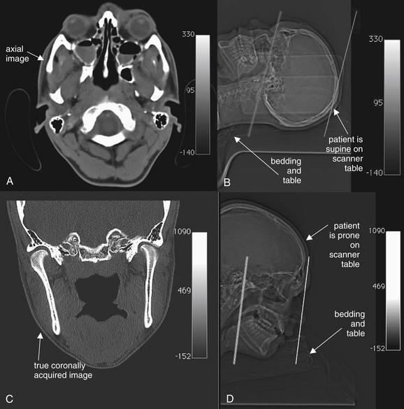
Figure 2-1 Differences between head and face computed tomography (CT).
Images are from the same patient. A, Head CT is typically acquired with the patient supine, with the scanner gantry tilted slightly to comply with the natural angulation of the cranial vault. This allows brain structures to be imaged in a true axial plane. Slice thickness is commonly around 5 mm. The axial image corresponds to the plane through the left line in the scout image, B. Axial facial images are acquired in the same position.
C, Facial CT requires axial and coronal images to be generated. In the past, patients were often positioned prone for facial CT to allow acquisition of true coronal images. The coronal image in C corresponds to the coronal plane through the left line in the scout image, D. Today, multislice scanners using fine slice thickness (1.25 to 3 mm) allow high-resolution, reformatted images in multiple planes without repositioning the patient. Patients can be positioned in the usual supine position for a single volumetric data acquisition. The three-dimensional dataset can be “sliced” to produce images in any plane.
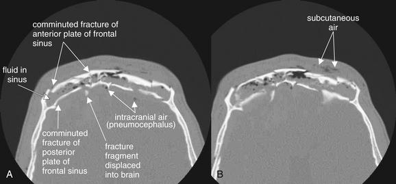
Figure 2-2 Frontal sinus fractures.
Facial fractures involving the sinuses are common and are usually not life-threatening injuries. These injuries may dissipate force, preventing intracranial injury. The sinuses could be called “airbags for the brain.” However, sometimes enough force is exerted to fracture not only the anterior wall of the sinus but also the posterior wall, which is a shared wall with the calvarium. These injuries are extremely serious, resulting in potential cerebrospinal fluid leak, intracranial hemorrhage, and intracranial infection.
A and B, In this patient, severely comminuted fractures of the anterior and posterior plates of the frontal sinus are present. The frontal sinus is nearly filled with fluid, presumably blood from the acute fractures. Air is present in the subcutaneous tissue, likely having escaped from the frontal sinus but also possibly entering through a facial laceration. Fracture fragments from the posterior wall of the frontal sinus have been displaced posteriorly into the calvarium. Air is also present within the calvarium. Inspection of the brain for hemorrhage should be performed using brain window settings, and dedicated brain computed tomography should be performed. Because the posterior wall of the sinus is fractured, this is a true neurosurgical emergency, not a simple facial fracture.
In the past, true coronal sections acquired with the patient in a prone position offered higher resolution than coronal reconstructions created from axial source images (see Figure 2-1). These high-resolution images have excellent sensitivity for even minimally displaced fractures. Modern multislice helical CT has the ability to create multiplanar sagittal and coronal, as well as three-dimensional, reconstructions from source data acquired with the patient in a supine position, eliminating the need to acquire true coronal images by patient and gantry repositioning. One cadaver study suggested that coronal plane facial reconstructions generated from axial fine-cut (1.25 mm) head CT images had a sensitivity of 97% for displaced fracture compared with coronally acquired images when interpreted by an experienced radiologist.1 The true sensitivity of facial CT is difficult to determine, as no independent gold standard for comparison is available to confirm negative CT results. Is a normal CT a true negative, or is it a false negative, having missed a fracture? This study assigns coronally acquired facial CT the role of diagnostic reference standard for comparison with coronal reconstructions from axially acquired images. In this study, facial fractures were generated in the cadavers by striking the cadaver heads in a standardized fashion. However, the exact number of fractures generated by this method is unknown, so it is impossible to determine whether either CT technique actually detected all fractures.
Why should we care about these issues as emergency physicians? Advantages of using coronal reconstructions rather than true coronally acquired images include reduced scan time, reduced radiation exposure (particularly to the radiosensitive lens of the eye), and utility in patients who cannot be repositioned for other clinical reasons, including cervical spine injuries (which prevent prone positioning) and life-threatening injuries that limit additional CT.
Interpretation of Facial Computed Tomography in the Setting of Trauma
The approach to interpretation of facial CT requires a knowledge base similar to that for head CT. Refer to Chapter 1, in which basic features of CT, including right–left orientation, Hounsfield units, and window settings, are explained in detail. For facial CT, we rely on two primary window settings: bone windows for bony injury from facial trauma, and soft-tissue windows for soft-tissue injury from trauma and for other indications, such as assessment of soft-tissue infections and masses. When interpreting facial CT for trauma, review the entire CT using bone windows, and then repeat the process using soft-tissue windows. Throughout this chapter, you will find carefully annotated images depicting a range of pathology. The figure captions lead you through the interpretation of the specific findings, including the optimal choice of window setting. Unlike head CT, in which axial images are often the only image set reviewed, facial CT images are generally acquired and displayed in both axial and coronal planes. Sagittal planes and three-dimensional reconstructions are selectively used to depict injuries and pathology that are incompletely characterized by axial and coronal images.
A few sources of error in interpretation deserve mention here. Use of the wrong window setting prevents detection of important pathology. For example, soft-tissue windows do not allow detailed inspection of bone, so nondisplaced fractures may not be seen. Emergency physicians may not be familiar with detailed anatomy of facial bones, so normal structures such as sutures and foramen may be mistaken for fractures. If a patient has a unilateral complaint or injury, use the normal side for comparison when inspecting the CT images. Recognize that CT reconstructions often have reconstruction artifacts, such as the “seams” where two image sets are pieced together by the computer (see Figure 2-15 on page 62). These artifacts can be distinguished from fractures, as the “step-off” created by reconstruction artifact extends across the entire CT image, not just through bone. Understanding that these artifacts may exist can prevent artifact from being misconstrued as fracture. Asymmetrical positioning of the patient within the CT gantry also results in asymmetry of CT images, which may be misinterpreted by the novice as injury or pathology (see Figure 2-16, B, on page 62 where asymmetry is caused by patient positioning). Note the patient’s position on the CT images as you begin your interpretation so that you may take position into account and avoid this pitfall.
CT for facial trauma is performed without IV contrast. Bone windows are used to evaluate most injuries, as they demonstrate both fractures and air–fluid levels well. Soft-tissue windows can depict subcutaneous hematomas and swelling, but these injuries rarely require specific therapy. Two important exceptions must be recognized. First, soft-tissue windows may reveal intracranial injury, although the field of view of facial CT does not include the entire brain, and brain (head) CT should be ordered if intracranial injury is suspected (see Chapter 1). Second, injuries to the globe and other orbital contents may require emergency ophthalmologic intervention and are seen on soft-tissue windows. Most remaining traumatic facial injuries are fractures and injuries to sinus spaces, best seen using bone windows. Our approach uses a cephalad to caudad orientation. Consequently, we first discuss frontal bone fractures, followed by orbital and ethmoid sinus injuries; maxillary, zygomatic, tripod, nasal, and Le Fort midface fractures; and finally, dental and mandibular injuries.
Frontal Bone Fractures
Frontal bone fractures (see Figure 2-2) can be isolated facial injuries or can extend intracranially. The frontal sinus has an anterior and posterior wall. Fractures to the anterior plate alone are facial injuries, requiring cosmetic surgical treatment if depressed. Fractures to the posterior plate are calvarial injuries and carry several risks, including intracranial infection (from contamination of the cerebrospinal fluid with nonsterile air and fluid from the frontal sinus), intracranial hemorrhage, and direct traumatic brain injury if fracture fragments are projected posteriorly. Inspect for frontal sinus injury first using bone windows and then using brain windows. On bone windows, examine the anterior and posterior plates for discontinuities. Anterior plate fractures may require otolaryngology or plastic surgery consultation. Posterior plate fractures require neurosurgical consultation. Some patients have a hypoplastic frontal sinus, with no airspace—the anterior and posterior plates are fused as one bone, so any fracture requires neurosurgical consultation. The normal frontal sinus is air-filled (black). Look for opacification of the frontal sinus (gray on bone windows), indicating traumatic blood. In the absence of trauma, frontal sinusitis can have a similar appearance. When fractures of the posterior plate are present, look for intracranial air (pneumocephalus, black) using bone windows. Inspect for bone fragments that have been displaced posteriorly. Switch to brain windows and inspect for intracranial hemorrhage, which will appear white (see Chapter 1). Posterior plate fractures should prompt additional imaging with noncontrast head CT if this has not already been obtained.
Orbital Injuries
Fractures to the orbit are detected by reviewing CT images on bone windows. The plane of the fracture and direction of displacement of fracture fragments varies, so axial and coronal images should be reviewed to ensure detection of any fractures. If the patient has a unilateral injury, use the normal side for comparison. As discussed in Chapter 1, bony injury may be seen directly as a discontinuity in the bone making up the walls of the orbit or adjacent sinus space (sometimes called a cortical defect). However, some minimally displaced fractures may be difficult to recognize directly, and indirect signs of injury may draw your attention to a likely fracture. These signs include fluid in normally air-filled spaces—the ethmoid sinuses medial to the orbit and the maxillary sinuses inferior to the orbit. An air–fluid level may be present, or the sinus space may be completely opacified with blood products. On bone windows, bone appears quite white, air appears completely black, and blood and other soft tissues appear various shades of gray. Another indirect sign of orbital fracture is air within the orbit. Again, on bone windows, air in the orbit will appear black. Air is not normally found within the orbit but may be introduced from adjacent sinus spaces when fractures occur. Figures 2-3 through 2-6 (see also Figure 2-14) demonstrate common orbital injuries, including medial and inferior orbital fractures with secondary signs of injury to adjacent sinus spaces. Entrapment of extraocular muscles may be seen on CT, with bone fragments directly impinging on muscle soft tissue. Sometimes orbital fat is seen projecting through an orbital fracture. Soft-tissue windows may help to determine whether entrapped soft tissue is muscle or fat. Fat appears nearly black on soft-tissue windows, while extraocular muscles have a light gray appearance. The density in Hounsfield units (HU) can also be measured directly using tools on most digital picture archiving and communication systems. Fat has a density of approximately -50 HU, whereas muscle density is approximately +50 HU.
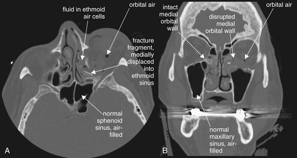
Figure 2-3 Orbital fracture: Medial wall fractures.
In this unenhanced computed tomography image, viewed on bone windows, fractures of the medial wall of the orbit are evident. Force directed at the globe often results in fractures of the medial wall, including the paper-thin lamina papyraceae. Several features of this fracture pattern are evident. Here, the fracture itself is visible, although in some cases this may be difficult to see. This sliver of bone has tipped medially into the adjacent ethmoid sinus (A). The ethmoid sinus, normally an air-filled space, is fluid-filled—in this case, due to bleeding from the acute fracture. Compare this with the normal sphenoid and maxillary sinuses, which are well aerated. Air has escaped from the ethmoid air cells into the left orbit. An inferior orbital fracture involving the left maxillary sinus is also present, investigated in more detail in Figures 2-4 through 2-6 and Figure 2-14. The bone window setting is ideal for depicting the preceding findings, since air alone appears black on this setting.
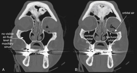
Figure 2-4 Orbital fracture: Subtle inferior wall fractures.
A and B, Inferior orbital fractures (also called orbital floor fractures) involve the superior wall of the adjacent maxillary sinus. These can be difficult to recognize on axial views, as the fracture fragment may lie in the axial plane. In contrast, these are usually easily recognized on coronal reformations. In this example, minimally displaced fractures of the orbital floor are visible—compare the discontinuity of the left orbital floor with the continuous right orbital floor. Air within the orbit (orbital emphysema) also is evidence of this fracture—air likely leaked from the maxillary sinus into the orbit. A common associated finding would be an air–fluid level in the maxillary sinus due to bleeding into the sinus from the fracture. On these images, no air–fluid level is visible. This may be a function of the patient’s position at the time of computed tomography (CT) scan acquisition. Although the coronal reformations may look like the patient is in an upright position, don’t be fooled. The patient was supine during the CT scan, and any blood would have pooled posteriorly in the maxillary sinus. These slices were reconstructed at a relatively anterior position through the sinus and could miss pooled blood products.
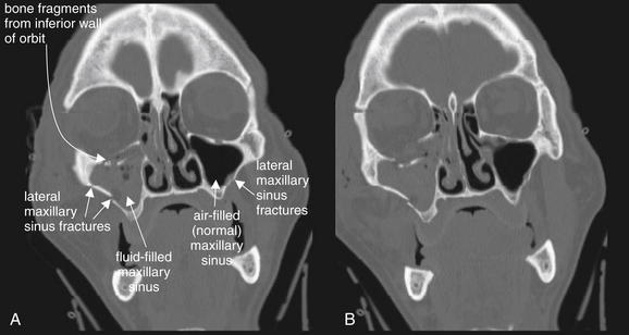
Figure 2-5 Orbital fracture: Blowout.
Most orbital fractures are of the “blowout” type: force applied to the globe and orbital rim increases pressure within the orbit, and fractures occur in the weak medial, inferior, or both walls of the orbit, forcing the orbital wall to blow out into the adjacent ethmoid or maxillary sinus. A and B, In this patient, an inferior blowout has occurred, with bone fragments being displaced inferiorly into the maxillary sinus. Fluid (blood from acute fractures) fills the maxillary sinus, a common finding associated with facial fractures. An air–fluid level is not seen, because this patient was in a supine position during the computed tomography scan and the coronal reformations are parallel to the patient’s position in the scanner. In addition, this patient’s maxillary sinus is nearly filled with blood. Additional fractures are present, including ethmoid fractures revealed by fluid in the ethmoid air cells and a lateral maxillary sinus fracture.
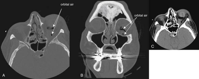
Figure 2-6 Orbit injury: Retrobulbar emphysema.
Orbital fractures often result in the escape of air from adjacent sinus spaces into the orbit. Because the orbit does not normally contain air, the presence of air within the orbit should be interpreted as strong evidence of a fracture after trauma, even if the fracture line itself is not visible. A (axial view) and B (coronal view), In this example, medial (ethmoid) and inferior (maxillary) fractures are present and are likely the sources of the orbital air. A bone window setting is ideal for detecting both the fracture and orbital air. On this setting, bone appears bright white, air appears completely black, and soft tissues are an intermediate gray. A soft-tissue window may make recognition small amounts of air more difficult, because orbital fat is nearly black on this setting (C, same image as A but viewed on soft-tissue window).
Injuries to the orbital contents (soft tissues) are best seen using soft-tissue windows. Again, axial and coronal images should be inspected. Normally, the globe is quite round in cross section. The lens appears bright (light gray), while the anterior and posterior chambers are lower in density and appear a darker gray. The choroid and sclera surrounding the eye are similar in density to the lens and appear light gray. Orbital fat is normally dark, nearly black on soft-tissue windows due to its low density. The extraocular muscles are denser than both orbital fat and vitreous humor within the globe and appear light gray. They are normally quite discrete and well marginated, as they are surrounded by dark orbital fat, which provides contrast. The optic nerve is also seen in the orbit posterior to the globe—it shares the same “soft tissue” density with extraocular muscles and appears light gray. CT reveals soft-tissue injury, which can only be suspected with the use of facial x-ray (Figure 2-7). Figures 2-8 through 2-13 show injuries to orbital contents imaged with CT, with the contralateral side providing a good example of normal orbital anatomy.
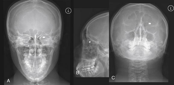
Figure 2-7 Orbit injury: Orbital foreign body.
Anterior–posterior (A), lateral (B), and submental (C) views of the face using plain x-ray reveal an orbital foreign body. The patient is a 16-year-old man shot with a pellet gun. Although plain film is useful for detecting metallic and other dense orbital foreign bodies, it provides little information about the globe or other structures in the orbit. A computed tomography scan was also performed in this patient (Figure 2-8).
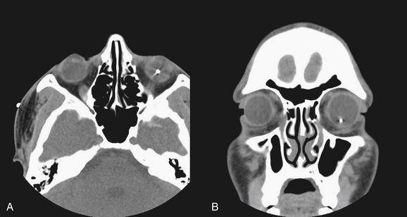
Figure 2-8 Globe rupture with intraocular foreign body.
This 16-year-old man was shot in the face with a pellet gun. Plain x-ray (Figure 2-7) demonstrated an orbital radiopaque foreign body. A (axial view) and B (coronal view), This computed tomography scan confirms that the pellet is within the left globe—an ophthalmologic emergency. The dense object creates some metallic artifact around it. These images use soft-tissue settings to allow inspection of the globe and orbital contents. Amazingly, the remainder of the orbital contents appear normal. Bone windows should also be inspected to allow detection of any associated fractures. The patient was taken to the operating room for removal of the foreign body.
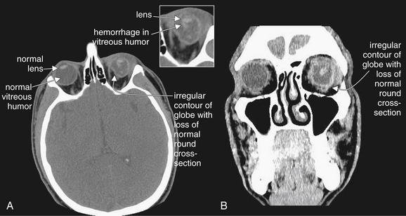
Figure 2-9 Ocular injury with globe laceration and rupture.
This patient fell in a bathroom, striking the left globe against an unknown object. A (axial view) and B (coronal view) soft-tissue CT images reveal a ruptured globe with associated vitreous hemorrhage. The left globe is obviously not round in cross-section because of rupture and extrusion of some ocular contents. Compare with the normal right globe. The lens appears to be in a relatively normal position. Dense intraocular hemorrhage is visible in the posterior chamber, against the darker background of normal vitreous humor.
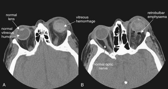
Figure 2-10 Ruptured globe with lens dislocation and intraocular hemorrhage.
This patient sustained a ruptured left globe from airbag deployment. A and B, The axial computed tomography (CT) images viewed on soft-tissue windows reveal several important findings. First, dense material is present in the posterior chamber of the left eye, consistent with intraocular hemorrhage. Compare with the normal right globe. Second, the lens cannot be identified in its normal location in the left eye, suggesting dislocation. Recognize that a patient may not be positioned symmetrically in the CT scanner during scan acquisition, resulting in an asymmetrical appearance of structures in the CT images. This may simulate pathology, so confirmation of this suspected injury requires careful inspection of adjacent slices in the stack of CT images. Fresh blood in the posterior chamber is also isodense with the lens, making detection of the lens difficult. B, Air is also visible posterior to the globe. Small amounts of air may be difficult to see against the dark gray background of orbital fat on soft-tissue windows and may be more apparent on bone windows. These should be inspected to detect associated sinus fractures, which are the likely source of orbital air.
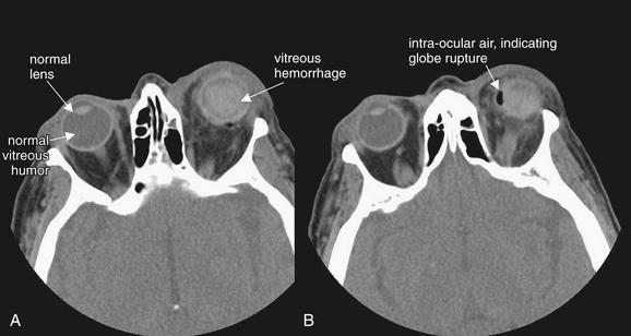
Figure 2-11 Ocular injury: Globe rupture with vitreous hemorrhage and lens dislocation.
This patient was struck in the left eye by a deploying airbag, resulting in vitreous hemorrhage and lens dislocation (A and B, axial CT images, soft-tissue window). These are discussed in detail in Figure 2-10. An additional finding mandates immediate operative therapy: air is present within the globe, indicating globe rupture (B).
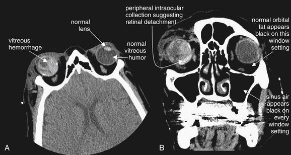
Figure 2-12 Ocular injury with retinal detachment and vitreous hemorrhage.
This patient also suffered an ocular injury during airbag deployment. A (axial image) and B (coronal image), Like the patient described in the preceding figures, this patient has posterior chamber hemorrhage, indicated by dense material posterior to the lens position. This patient had undergone prior ocular surgery and does not have a native lens in the right eye, explaining the absence of a visible lens—though this appearance would also be consistent with lens dislocation. The patient also has retinal detachment with subretinal blood, visible as hyperdense collections on the periphery of the globe. Retinal detachment and vitreous hemorrhage may be indistinguishable by computed tomography, though both would require emergency ophthalmologic consultation. The soft-tissue window setting in this figure would not be appropriate for detection of orbital air, since the window setting has been adjusted in such a manner that orbital fat appears as black as air. Air could be detected by adjusting the window setting, for example, to bone windows.
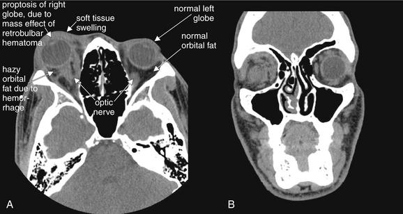
Figure 2-13 Orbit injury: Postbulbar hemorrhage (retrobulbar hematoma).
Orbital trauma can result in significant, sight-threatening injury. In this case, hemorrhage posterior to the globe is exerting mass effect, displacing the globe anteriorly and resulting in proptosis. Retrobulbar hematoma can exert pressure on the optic nerve, resulting in permanent blindness. This patient underwent emergency lateral canthotomy to relieve the elevated orbital pressure.
A (axial) and B (coronal) images are shown on soft-tissue windows to highlight the globe and orbital soft tissues. Bone windows should also be reviewed to allow detection of associated fractures. Several computed tomography findings are evident. First, the right globe is proptotic compared with the normal left globe. Second, soft-tissue swelling of the eyelid is evident on the patient’s right, compared with the left. Third, the orbital fat appears hazy on the right, compared with the normal black appearance of orbital fat on the patient’s left—this is consistent with hemorrhage. The patient’s globes are intact bilaterally, with normally positioned lenses and normal vitreous (gray).
Important injuries to orbital contents include globe ruptures, particularly related to intraorbital and intraocular foreign bodies; vitreous hemorrhage; lens dislocation; retinal detachment; and retrobulbar emphysema and hematoma.
Global rupture
Globe rupture (see Figures 2-7 through 2-11) may result from either blunt or penetrating trauma. In the setting of penetrating trauma, a radiopaque foreign body may be seen within the globe. High-density foreign bodies (e.g., metal, stone, or glass) may be readily seen on CT as bright white intraocular densities. These may also be visible on x-ray (see Figure 2-7), but CT offers more definitive localization within the globe rather than in the orbit (see Figure 2-8). Lower-density materials such as wood may be isodense with normal intraocular contents or with intraocular blood. They may be invisible on x-ray and CT and may require magnetic resonance imaging (MRI) or ultrasound for detection. Globe rupture may result in disruption of the normal spherical contour of the globe (circular in cross section). The globe may appear irregular and smaller than the normal contralateral side (see Figure 2-9). Intraocular air is also proof of globe rupture following trauma (see Figure 2-11). As with air in other locations, air is black on all window settings and is readily visible within the globe, contrasted against denser (therefore brighter) globe contents.
Vitreous hemorrhage
Vitreous hemorrhage (see Figures 2-9 through 2-12) can occur with blunt or penetrating globe trauma and is not proof of globe rupture when seen in isolation. Hemorrhage within the globe is higher density than the normal vitreous humor and thus appears brighter against the dark gray background of the vitreous. Blood can be isodense with the lens of the eye, sometimes make it difficult to determine whether the lens is properly located.
Lens dislocation
On soft-tissue windows, the lens is normally found as a biconvex bright disc in the anterior globe (see Figures 2-9 through 2-12). The two pointed edges of the lens should each tangentially contact the globe circumference. A thin crescent of low-density aqueous humor should be visible as a dark gray region anterior to the lens. Lens dislocation is recognized by the absence of the lens from its normal location—the lens may be visible in another region of the eye or may be obscured by intraocular blood (see Figures 2-10 and 2-11). In some patients, the lens is surgically absent, so it is important to take a thorough history when the lens is not found in normal position (see Figure 2-12).
Retinal detachment
Retinal detachment may be seen on CT scan (see Figures 2-12 and 2-27). Normally, the retina is invisible on CT scan, as it is adherent to the periphery of the globe, is extremely thin, and is isodense with other ocular contents. However, when retinal detachment occurs, the retina is lifted up by blood or other soft-tissue material. This can result in a peripheral convexity projecting into the vitreous humor (see Figure 2-27). In some cases, other ocular injury, such as vitreous hemorrhage, may make retinal detachment impossible to recognize. If retinal detachment is the only suspected injury, CT should not be used for evaluation, as radiation to the eye contributes to cataracts (see later discussion), and other modalities including ocular ultrasound can be used for diagnosis without radiation exposure.
Retrobulbar emphysema and hematoma
Retrobulbar emphysema (also called orbital emphysema) (see Figures 2-6 and 2-10) can be seen on both soft-tissue and bone windows, as air appears black on both window settings. It is more easily seen on bone windows, where orbital fat appears gray. On soft-tissue windows, orbital fat appears nearly as black as air. Usually, orbital emphysema requires no specific treatment and is a secondary sign of a fracture to the medial or inferior orbital wall, with air entering the orbit from the ethmoid or maxillary sinus.
Retrobulbar hematoma (see Figure 2-13) is a more important injury, as ongoing hemorrhage in this location can result in rising pressure, compressing and injuring the optic nerve. This can progress to orbital compartment syndrome, which can result in blindness unless lateral canthotomy is performed. Retrobulbar blood is visible on soft-tissue windows. Fresh blood is intermediate gray, similar to the appearance of the optic nerve and extraocular muscles. It blurs the contours of these structures, which are normally quite distinct and outlined by dark orbital fat. An additional finding that suggests high orbital pressure in this setting is proptosis of the affected eye.
Ethmoid Sinus Injuries
Ethmoid fractures often accompany other orbital injuries—search for these injuries using bone windows. The ethmoid sinuses lie medial to the orbits, and blows to the orbits can result in medial blowout fractures of the thin lamina papyracea (see Figure 2-3). In addition, direct anterior–posterior blows to the nose often cause ethmoid fractures, as the ethmoid sinuses lie deep to the nose. The normal ethmoid sinuses are air-filled and appear black (see Figure 2-21). Fractures of the ethmoid sinuses often allow air to escape into the orbits (see Figure 2-3). Infraorbital air appears black, as described earlier. Bleeding from ethmoid fractures causes opacification of the ethmoid air cells, which then appear gray on both bone and soft-tissue windows (see Figures 2-3 and 2-16).
Midface Fractures
After assessing the orbit, inspect other structures of the midface.
Maxillary fractures
Maxillary fractures (Figure 2-14; see also Figures 2-15, 2-16, 2-18, and 2-19) can be isolated injuries or part of a larger pattern of injury, such as the inferior orbital fractures, tripod fractures, or Le Fort fracture patterns. Figure 2-14 shows unilateral maxillary sinus fractures with a normal contralateral side for comparison. Use bone windows to evaluate the maxillary sinus for fracture. Defects in the thin bony wall can often be seen directly. Fluid in the maxillary sinus appears gray and should be suspected of being blood from a fracture following trauma—even if the fracture itself is not seen. Always consider the differential diagnosis for opacification of the maxillary sinus. This can include both traumatic blood (see Figure 2-14) and preexisting sinus disease (see Figure 2-22). Typically, sinus blood fills the sinus in a dependent position (usually posterior first, as the patient is supine for CT), forming an air–fluid level. Sinusitis from infectious or allergic causes usually creates more circumferential and often lobulated thickening of the soft tissues lining the sinus. Fractures to the anterior and posterior walls of the maxillary sinus are best recognized on axial images (see Figure 2-14, A), whereas fractures of the superior wall of the maxillary sinus (orbital floor) are better seen on coronal images (see Figure 2-14B). Both axial and coronal images should be inspected for this reason.
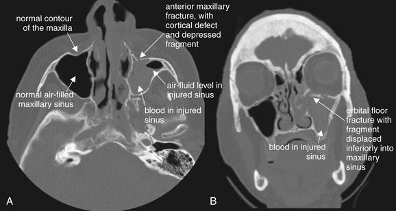
Figure 2-14 Maxillary fracture.
This patient has a minimally depressed fracture of the anterior wall of the maxillary sinus, with associated bleeding into the maxillary sinus. A, An air–fluid level marks the injured side; compare with the normal right maxillary sinus. B, On the coronal reformation, the opacified maxillary sinus is again visible. A fracture of the orbital floor is also visible.
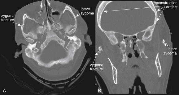
Many textbooks emphasize that bony rings rarely break in a single location—when one fracture is detected, a second fracture should be suspected and sought after. In practice, this is often true, but a single fracture location with comminuted fragments may dissipate force sufficiently to prevent a second fracture site. A, This patient has a comminuted fracture of the zygomatic arch. Compare the patient’s right (fractured) zygoma with the normal left. This patient does have additional fractures, including maxillary sinus and ethmoid sinus fractures, which are described in detail in other figures. B, The coronal view is a computer reconstruction, which has visible artifact at several levels. These artifacts can be distinguished from fracture lines because they extend across the entire image in a horizontal line. Try to identify additional reconstruction artifacts in the image.
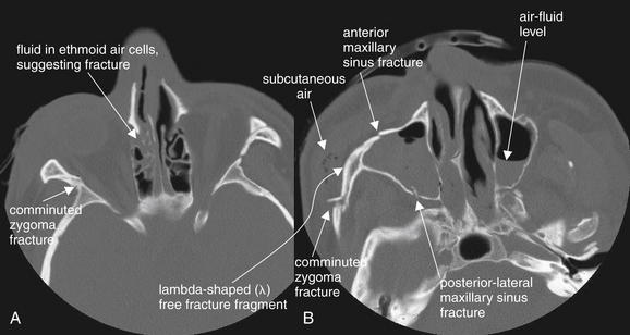
Figure 2-16 Zygomatic complex fracture (also called tripod fracture, malar fracture, or zygomaticomaxillary complex fracture).
The bony rings formed by the zygoma and walls of the maxillary sinus and orbit often fracture in a predictable pattern in response to an applied force—although the “real-life” patterns of fracture are often more complex than the textbook descriptions. A tripod fracture involves the zygomatic arch, inferior orbital rim, and anterior and lateral walls of the maxillary sinus. These fractures are depicted in the axial computed tomography images above, viewed on bone windows. A, Blood is present in the ethmoid sinuses, suggesting ethmoid fracture. B, Notice the lambda-shaped (λ) free fracture fragment, which creates instability of the inferior and lateral orbit.
Note the air–fluid levels in the bilateral maxillary sinuses, indicating blood associated with bilateral maxillary sinus fractures.
Zygomatic arch fractures
Fractures of the zygomatic arch are common and should be evaluated using bone windows. These are readily apparent on axial images, although coronal images can also reveal these fractures (Figure 2-15). The normal smooth curve of the zygomatic arch is disrupted by fracture. Like other ring structures, the zygomatic arch rarely fractures in a single location, although a comminuted fracture may dissipate enough force to prevent fracture in a second discrete location. Zygomatic arch fractures are frequently accompanied by other complex fracture patterns, including tripod fractures and Le Fort III fractures (described in detail later).
Tripod fractures
A tripod fracture (Figure 2-16) is also called a zygomatic complex fracture, malar fracture, or zygomaticomaxillary complex fracture. This fracture involves the zygomatic arch, inferior orbital rim, and anterior and lateral walls of the maxillary sinus. Look carefully at Figure 2-16, B. The fractures of the zygoma and maxillary sinus have created a lambda-shaped (λ) free fracture fragment—typical of tripod fracture. This fracture requires surgical repair, because it creates instability in the inferior–lateral orbit. Unlike a Le Fort III fracture (described later), the fracture does not extend to the pterygoid processes, so the face is not dissociated completely from the calvarium. When a zygomatic fracture is present, always inspect the inferior orbital rim and maxillary sinus to determine whether a tripod fracture has occurred.
Le Fort injuries
The Le Fort classification of midfacial fractures (Figures 2-17 through 2-20) is based on the work of the French physician Rene Le Fort using cadaver skulls, published in 1901.2 Le Fort described a series of midface fractures spanning from relatively stable maxillary injuries (Le Fort I) to complete craniofacial dissociation (Le Fort III). Not surprisingly, his description of fractures inflicted on skulls postmortem does not perfectly describe the range of injuries seen in living patients. However, the patterns he observed do form the basis for approaches to surgical repair. In reality, injuries are often combinations of the Le Fort I, II, and III patterns, with additional fractures frequently noted that do not conform to the Le Fort classification. Other midface fracture classifications have been described. From an emergency physician standpoint, critical issues include recognition of isolated facial fractures and those that concurrently involve the calvarium and thus pose risks of cerebrospinal fluid leak and subsequent infection (see the earlier frontal sinus fracture discussion). Patients with these injuries are often severely injured and intubated and thus may not be able to offer useful clinical information about neurologic or sensory complaints. Use of the Le Fort classification system can facilitate communication with physicians in other specialties—although simple description of the involved bones and planes of fracture can suffice and can be more complete and accurate.
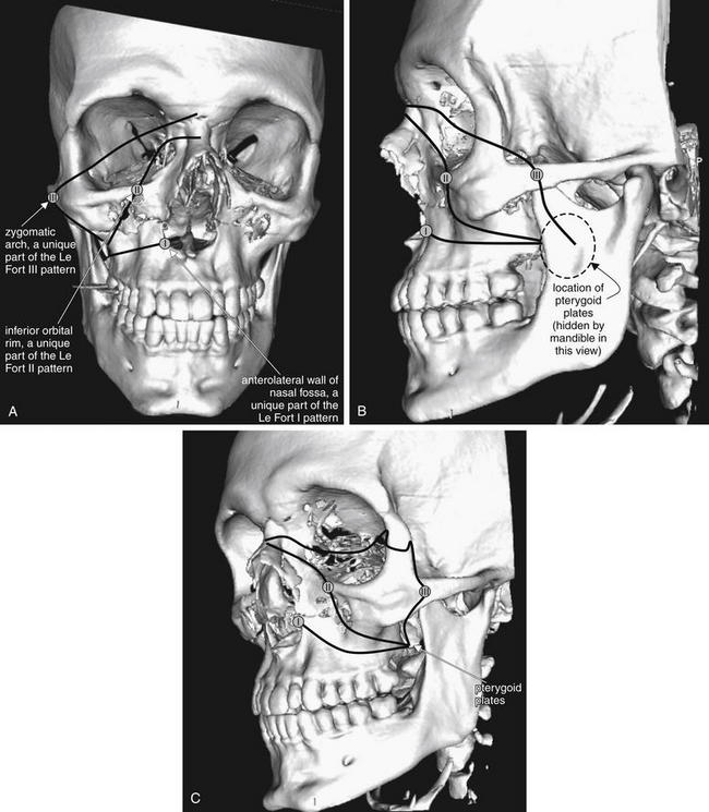
Figure 2-17 The Le Fort classification system for facial fractures.
All Le Fort fractures involve the pterygoid plates, plus at least one other unique fracture. Le Fort I fractures involve the anterolateral wall of the nasal fossa. Le Fort II fractures involve the inferior orbital rim. Le Fort III fractures involve the zygomatic arch. Inspection of each of these zones and the pterygoid plates can allow you to rule in or rule out each fracture type. Remember that more than one type may be present on each side of the patient’s face, and the fractures may or may not be bilaterally symmetrical.
Here, anterior–posterior (A), lateral (B), and oblique (C) views of the face are shown, taken from three-dimensional, surface-rendered computed tomography reconstructions. Black lines indicate the general path of the fracture in a Le Fort III–II–I pattern. The lines are intentionally drawn on only half of the figure, as Le Fort fractures need not be bilaterally symmetrical. A small circle has been placed along each line to mark a location unique to each fracture pattern, which can be used to help to rule in or rule out that pattern. This patient has visible bilateral Le Fort I fractures. The pterygoid plates are not visible in some views but lie posterior to the maxilla, hidden behind the ramus of the mandible.
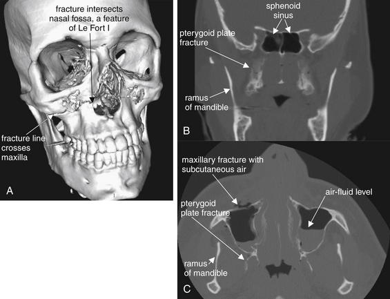
Figure 2-18 Le Fort I fracture.
This 30-year-old man was struck in the midface by a baseball at a minor league park. He presented with epistaxis, as well as some instability of the maxillary teeth, which were mobile as a unit. His computed tomography image shows fractures consistent with a bilateral Le Fort I pattern.
A, A three-dimensional, surface-rendered reconstruction shows the fracture line extending from the anterolateral nasal fossa, across the maxilla, and toward the pterygoid plates (not visible in this image). B, Coronal reconstruction, with the pterygoid fracture visible. C, Axial view.
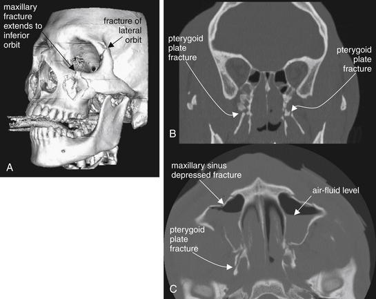
Figure 2-19 Le Fort II fracture.
This 24-year-old man was assaulted with the butt of a shotgun and sustained multiple facial fractures, which in general follow the Le Fort II pattern bilaterally. A Le Fort II fracture makes the midface mobile due to fractures through the maxilla, inferior orbital rim, and pterygoid plates. Additional fractures are present in this patient. No single computed tomography image shows the entire scope of the patient’s fractures, so selected images have been chosen to depict the most critical injuries. A, A three-dimensional, surface-rendered image shows a depressed maxillary fracture involving the inferior orbital rim on the left. This patient also has a fracture of the lateral orbit, a reminder that real-world fractures often do not adhere exactly to a Le Fort pattern. B, Coronal view. C, Axial view.
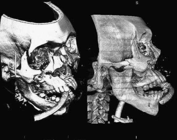
Figure 2-20 Le Fort III fracture and beyond.
This 34-year-old man sustained major facial fractures in a motor vehicle collision. Although his fractures could be described using the Le Fort classification, they are not symmetrical and have a complex pattern that defies the Le Fort categories. Three-dimensional, volume-rendered CT images are shown. Such reconstructions are particulary valuable to define spatially complex fractures. A, an oblique view from a vantage point superior to the patient’s right eye. B, a direct lateral view from the patient’s right. The patient is intubated and an endotracheal tube is visible entering the mouth and continuing past the hyoid bone.
Rhea and Novelline3 have described a simple method for detection of Le Fort fractures on CT scan (Table 2-2). They note that Le Fort I, II, and III fractures have in common fracture of the pterygoid plates, whereas each fracture pattern has a unique additional bony fracture not found in the other patterns. If the unique fracture is not present, the specific Le Fort pattern is ruled out. If the unique fracture is present, the particular Le Fort pattern must be confirmed by inspecting for the additional typical features of that fracture pattern. Le Fort I fractures always involve the anterolateral margin of the nasal fossa. Le Fort II fractures always involve the inferior orbital rim. Le Fort III fractures always involve the zygomatic arch. Remember that more than one type may be present on each side of the patient’s face, and the fractures may or may not be bilaterally symmetrical.
TABLE 2-2 Features of Le Fort Fractures∗
| Le Fort Pattern | Fracture Unique to Le Fort Pattern |
|---|---|
| I | Anterolateral margin of the nasal fossa |
| II | Inferior orbital rim |
| III | Zygomatic arch |
∗ All Le Fort fractures involve fractures of the pterygoid plates, plus an additional unique fracture.
Rhea JT, Novelline RA: How to simplify the CT diagnosis of Le Fort fractures. AJR Am J Roentgenol 184:1700–1705, 2005.
To assess systematically for a Le Fort fracture, first inspect for fractures of the pterygoid plates, which must be present. Because these structures may be unfamiliar to emergency physicians, we briefly review their location and appearance. As their name suggests, these plates or processes are thin, winglike (think of the pterodactyl, an ancient winged reptile) projections of the sphenoid bone and thus are located just caudad to the sphenoid sinus on coronal views (see Figure 2-18B). They are seen posterior to the maxillary sinuses on axial images (see Figure 2-18C). The ramus of the mandible is present lateral to the pterygoid processes, hiding them from view on the three-dimensional reconstructions in Figures 2-17 through 2-20. The proximity of the pterygoids and the mandible is no coincidence—the pterygoid processes are points of attachment for muscles of mastication, which move the mandible.
Once a pterygoid fracture is found, inspect for the unique fracture of each Le Fort pattern described earlier. Figure 2-17 shows the typical path of each Le Fort fracture, always passing through the pterygoid plates. Figures 2-18 through 2-20 explore Le Fort I, II, and III fractures in more detail.
Nasal fractures
Isolated nasal fractures require no imaging (as shown later), but nasal fractures are often found on CT performed for assessment of other facial injuries (Figures 2-21 and 2-22). Nasal fractures are evident on bone windows as discontinuities in the thin nasal bones. Often, blood is present in the nares, visible as a dark gray density on bone windows. Always inspect for associated injuries to the ethmoid and maxillary sinuses and orbits. The Le Fort I fracture pattern (see the earlier detailed description and Figures 2-17 through 2-18) involves the anterolateral nasal fossa and extends across the maxilla to the pterygoid plates, resulting in instability of the maxilla and maxillary teeth relative to the remainder of the face and skull.
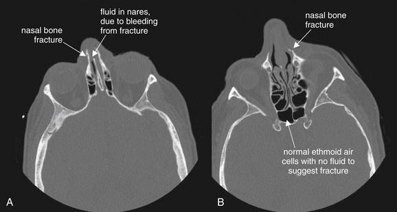
Isolated nasal fractures require no imaging—neither computed tomography nor plain film. However, sometimes nasal fractures are incidentally noted on imaging performed to evaluate for other suspected head and facial injuries.
In this patient, minimally displaced nasal bone fractures are present. Some blood is present in the nares (A), but the ethmoid air cells are well aerated, with no fluid to suggest fractures (B).
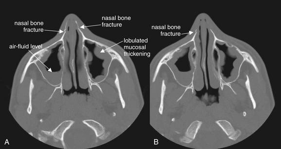
Figure 2-22 Nasal fractures with preexisting maxillary sinus disease.
This 14-year-old man struck himself in the nose with his knee while high-jumping, sustaining nasal fractures. As discussed earlier, sinus spaces should be inspected for air–fluid levels, which may indicate bleeding from an underlying fracture. A and B, axial CT images viewed on bone windows. In this patient’s case, the bilateral maxillary sinuses show significant mucosal thickening. In addition, the right maxillary sinus has an air–fluid level. Are these the sequelae of trauma? More likely, they indicate preexisting sinus disease. The bilateral abnormalities and the lobulated appearance are more likely findings of sinus inflammation. Blood from acute fractures would be expected to pool in the dependent portions of the sinuses, while inflamed mucosa (whether from infection or allergy) has a more circumferential appearance. Careful inspection of the bones of the sinuses reveals no fractures. The air–fluid level could represent blood from acute trauma or fluid associated with preexisting sinus disease. Sinus disease is a common incidental finding on computed tomography (CT) of the head performed for other indications. In the absence of clinical symptoms, the CT findings are nonspecific.
Dental and Mandibular Injuries
Facial trauma can result in dental–alveolar injuries—fractures of the alveolar bone surrounding maxillary and mandibular teeth. Traditionally, this has been evaluated with panoramic x-ray (Panorex), although CT performed for evaluation of other facial injuries readily detects dental–alveolar fracture. CT and panorex are compared later. Figure 2-23 demonstrates a maxillary dental–alveolar injury. These injuries are often treated by dentists or oral–maxillofacial surgeons and are not life threatening. On CT, inspect for cortical bone defects using bone windows. Review both axial and coronal images.
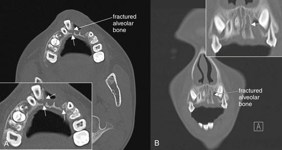
Figure 2-23 Dentoalveolar fracture.
Dental trauma can result in fracture of the alveolar bone surrounding the dental root. In this young man, the left central and lateral incisors have been completely avulsed. A, On the axial view, the right central incisor is displaced anteriorly and the surrounding alveolar bone is fractured (arrows, close-up view). B, On the coronal reformation, a fracture of the left maxilla is also seen (arrow, close-up view).
Mandibular fractures (Figures 2-24 through 2-26) can be evaluated by panorex or CT scan (see later comparison). Panorex (see Figure 2-24) uses a moving x-ray tube to generate a flattened planar projection of the curved mandible. As with other x-rays, on panorex, fractures may be visible as cortical defects, step-offs, or linear lucencies. On CT scan, inspect for cortical defects using bone windows. Minimally displaced fractures may be subtle. Solitary mandibular fractures are thought to be rare due to the arch or ringlike structure of the mandible. Stress in one location in the arch generates stress at other locations, and multiple fractures are common. Sometimes stress is sufficiently relieved by a single minimally displaced fracture. Displaced fractures (see Figure 2-26) may result in a second fracture location or in dislocation of the mandibular condyles from the temporomandibular joints. These joints are seen well on coronal reconstructions (see Figure 2-26), so both axial and coronal images should be reviewed.
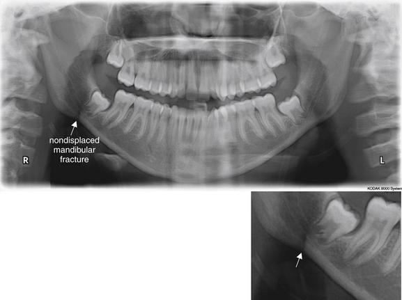
Figure 2-24 Mandibular fracture. Which imaging modality is the gold standard, Panorex or computed tomography (CT)?
Traditionally, Panorex plain film has been considered the gold standard for diagnosis of mandibular fractures. The wide availability of CT has encouraged the replacement of Panorex with CT as a common imaging modality for this indication. The two modalities are sometimes complementary. In this case, the Panorex shows a linear lucency adjacent to the right mandibular angle posterior to the posteriormost molar, which represents a fracture (arrow, close-up view). The fracture was not recognized on CT, although a left temporomandibular joint dislocation was recognized on CT but not on Panorex.
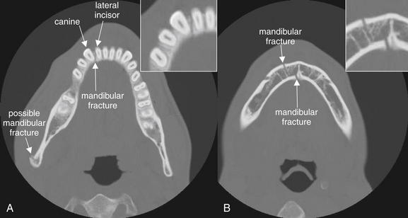
Figure 2-25 Mandible fracture: Nondisplaced.
Fractures of the mandible are classically described as rarely solitary, as the mandible forms a rigid ring not easily broken in a single location. Sometimes isolated fractures do occur, but once one fracture has been detected, a careful search should be conducted for additional fractures. Sometimes a single fracture is accompanied by dislocation of one or both mandibular condyles at the temporomandibular joint. A, In this patient, an isolated fracture of the anterior mandible is present, dividing between the right canine and the lateral incisor. A possible second fracture is seen at the mandibular ramus. B, The original fracture line is again seen, now zigzagging through the mandible. Cortical defects are visible on both mandibular surfaces.
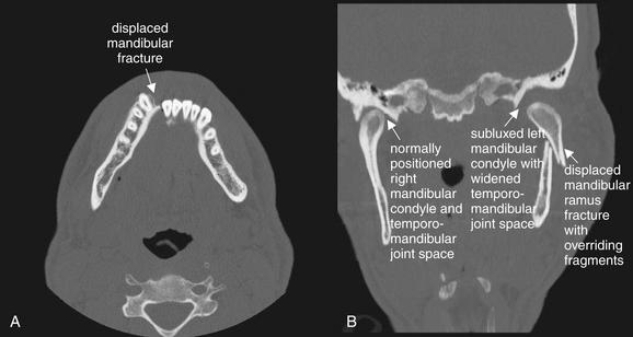
Figure 2-26 Displaced mandibular fracture.
When a significantly displaced mandibular fracture occurs, a second fracture or a dislocation of the mandibular condyle is nearly inevitable. This patient has both. A, On the axial view, a significantly displaced mandibular symphysis fracture is seen. B, On the coronal view, the left mandibular ramus is fractured and overriding, and the left mandibular condyle is subluxed. Compare with the normally positioned right mandibular condyle.
Interpretation of Facial Computed Tomography for Nontraumatic Conditions
We have discussed interpretation of CT scan for facial trauma in detail. We now turn to interpretation of CT scan performed for evaluation of nontraumatic facial abnormalities. For most of these applications, CT scan is performed with IV contrast. Soft-tissue windows provide the best visualization of important anatomic structures. Bone windows may occasionally provide additional clinically relevant information.
Rarely, metastatic tumors such as melanoma, prostate, and lung tumors can involve the eye, so CT with IV contrast should be considered in evaluation of patients with these conditions who present with eye complaints (Figure 2-27).
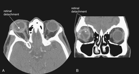
Figure 2-27 Choroidal metastases resulting in retinal detachment.
This elderly male presented clinically as though with a periorbital or orbital cellulitis but failed to improve with antibiotics. Computed tomography with intravenous (IV) contrast was performed due to suspicion of orbital infection. IV contrast is not used in the setting of facial trauma, as it is unnecessary for detection of fractures, air, lens dislocation, intraocular hemorrhage, or dense intraorbital or intraocular foreign bodies. When infection or malignancy is suspected, IV contrast should be given to allow enhancement of hypervascular pathology. This patient was found to have choroidal metastases from a known non–small cell lung carcinoma. Several malignancies, including lung and prostate neoplasms and melanoma, can metastasize to the orbit or globe. A, In this patient, a lens-shaped region of increased density is seen at the posterior right globe near the optic disc, consistent with retinal detachment in this location. B, Additional areas of retinal detachment are seen on the coronal view. Spontaneous or traumatic retinal detachment would have a similar appearance and could be detected without IV contrast.
Orbital Cellulitis and Abscess
Suspected orbital cellulitis or abscess can be assessed with CT scan with IV contrast. A discussion of the clinical indications for imaging is presented later. In the earlier discussion on orbital trauma, we reviewed the normal appearance of the globe and orbital contents. The normal globe is round in cross-section on both axial and coronal images. The vitreous humor is intermediate gray on soft-tissue windows. Normal orbital fat has a dark gray to nearly black appearance on soft-tissue windows. It outlines the extraocular muscles and optic nerve, which usually have discrete margins and a light gray appearance, reflecting their soft-tissue density. The normal orbit contains no air, although occasionally air may become trapped beneath the eyelid following physical examination.
Periorbital (preseptal) cellulitis
In periorbital (preseptal) cellulitis, soft-tissue inflammatory changes are restricted to the region anterior to the septal plate of the eyelids and do not involve other orbital contents. These inflammatory changes may include thickening of the eyelid and periorbital soft tissues, as well as inflammatory stranding of the subcutaneous fat. Stranding is a smoky or light gray appearance found in inflamed fat. Normal subcutaneous fat, such as orbital fat, is nearly black. As inflammation develops, an increase in soft-tissue water content occurs. This increases the density of fat tissue. On CT scan, increasing density results in a brightening of color.
Orbital (postseptal) cellulitis
In orbital (postseptal) cellulitis (Figures 2-28 and 2-29), inflammatory changes involve the orbital contents. Orbital fat develops the brightening or smoky appearance of fat stranding. As a result, the margins of extraocular muscles and the optic nerve become less distinct. Swelling of orbital contents may push the globe anteriorly, resulting in proptosis.
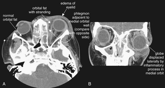
Figure 2-28 Orbital cellulitis.
Computed tomography (CT) is often used to distinguish orbital from periorbital cellulitis. Both conditions may have periorbital soft-tissue swelling. However, on CT, orbital cellulitis should also demonstrate stranding of orbital fat. Proptosis may be present if sufficient soft-tissue swelling occurs within the orbit to displace the globe. Intravenous contrast is given when orbital infection is suspected, as it will result in enhancement of hypervascular lesions. Neoplasms invading the orbit can present in a similar fashion to infection and can be detected by contrasted CT. In this patient, soft tissues anterior to the globe are thickened (compare with normal side) (A), though this does not distinguish preseptal from post septal cellulitis. Mild proptosis is present. The orbital fat shows inflammatory stranding, a hazy appearance compared with the normal right orbital fat. A thin enhancing collection is present along the medial wall of the left orbit, possibly representing an early abscess or phlegmon. The ethmoid sinuses are completely opacified, a finding described in detail in the next figure. B (coronal view), Lateral displacement of the globe is visible. The patient improved with antibiotics without undergoing surgery.
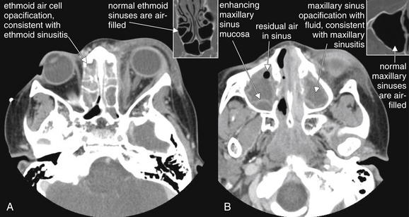
Figure 2-29 Sinus disease leading to orbital cellulitis.
This is the same patient depicted in Figure 2-28, with orbital cellulitis confirmed by computed tomography. A, The source of this infection is likely ethmoid sinusitis, as the ethmoid and maxillary sinuses are completely opacified with fluid. The ethmoid spaces are separated from the orbit only by the paper-thin lamina papyracea. B, Because intravenous contrast was given, the inflamed mucosa of the maxillary sinus is visible as an enhancing serpiginous line on the periphery of the sinus space. This likely separates the inflamed and thickened mucosa from the residual sinus space, which is then secondarily filled with fluid. Normal ethmoid (A) and maxillary (B) sinuses are shown in small boxes for comparison.
Orbital abscess
If a frank orbital abscess is present (Figures 2-30 and 2-31), IV contrast will result in enhancement of the lesion. Enhancement is an increase in the Hounsfield units of tissue following administration of IV contrast, resulting in a brighter appearance on CT. It reflects increased blood flow and vascular permeability in inflammatory, infectious, or neoplastic conditions. The rim of the abscess typically appears bright due to enhancement. If the abscess contains relatively low-density liquid pus, the center of the abscess will have a dark gray appearance on soft-tissue windows. This will be similar in density to the vitreous humor within the globe. Occasionally, abscesses may contain air, which will appear black on all window settings.
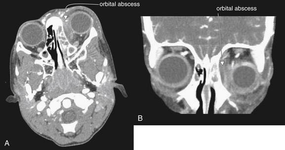
Figure 2-30 Orbital abscess, developing in the setting of ethmoid sinusitis.
In these contrast-enhanced facial computed tomography images, a left orbital abscess is visible. Several distinct features are present. A, Axial view, soft-tissue windows. The left eye demonstrates proptosis, due to mass effect of the abscess within the left orbit. B, Coronal view, soft-tissue windows. The left eye is displaced laterally and inferiorly, again by mass effect of the abscess. The orbital fat normally has a dark, nearly black appearance on soft-tissue windows. Here inflammation leads to fat stranding, giving the orbital fat a smoky gray appearance. Compare the fat of the left orbit to that of the right orbit (A and B). The abscess obscures the normal appearance of the extraocular muscles, which appear as gray tissue density. The abscess is visible as a spindle-shaped collection hugging the medial wall of the left orbit, with an enhancing rim. The contents of the abscess are fluid density, similar to the density of fluid in the adjacent ethmoid sinuses—the likely source of the orbital infection. Compare this appearance with the normally air-filled ethmoid sinuses on the patient’s right. Figure 2-31 demonstrates these features in detail.
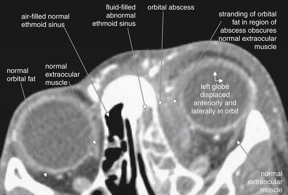
Figure 2-31 Orbital abscess, developing in the setting of ethmoid sinusitis.
This contrast-enhanced facial computed tomography image details features of the preceding figure. The left eye is displaced anteriorly and laterally by mass effect of an orbital abscess. Compare the fat of the left and right orbits. The abscess obscures the normal appearance of the extraocular muscles, which appear as a thin slip of gray tissue density.
Adjacent sinus infections
Orbital abscesses and cellulitis commonly originate from infections of adjacent sinus spaces (see Figures 2-28 and 2-29). The ethmoid and maxillary sinuses should be carefully inspected for abnormal opacification or mucosal thickening, which may indicate sinusitis. Normally, the sinuses are air-filled and black. Findings of sinusitis are discussed next.
Sinusitis
Sinusitis may involve the frontal, maxillary (Figure 2-32; see also Figures 2-22 and 2-29), ethmoid (see Figures 2-28 through 2-31), and sphenoid (see Figure 2-32) sinuses. Controversy remains about the specificity of CT abnormalities for the diagnosis of sinusitis (see later discussion). The normal sinuses are air-filled and black (see Figure 2-14 for maxillary, Figure 2-21 for ethmoid, and Figure 2-3, A for sphenoid). The normal sinus mucosa is extremely thin and essentially invisible on CT scan. In general, sinusitis results in circumferential mucosal thickening in the involved sinuses, appearing gray on both bone and soft-tissue windows. Thickened mucosa may have an undulating or lobulated appearance (Figure 2-33; see also Figure 2-22). An air–fluid level may also be present, or the sinus may be completely opacified by the combination of mucosal thickening and fluid. With administration of IV contrast, the sinus mucosa may enhance (see Figure 2-29B). Figure 2-33 compares normal maxillary sinuses with sinuses showing fluid from fracture and mucosal thickening from sinusitis. CT alone cannot determine the cause of sinus mucosal thickening, as thickening may result from infectious or allergic causes. Patients with CT abnormalities may be asymptomatic—clinical judgment must be used to determine the significance of the CT findings. Sinusitis can result not only in orbital infection, as described earlier, but also in meningitis (see Figure 2-32) or brain abscess. As a result, when a patient is found to have sinus disease on CT scan, the differential diagnosis must continue to be evaluated, as fever and headache may reflect simple sinusitis or more ominous intracranial infection.
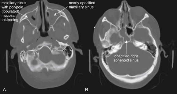
Figure 2-32 Paranasal sinusitis, complicated by development of Streptococcus pneumoniae meningitis.
This 60-year-old man presented with profoundly altered mental status and vomiting. His head CT demonstrated severe sinus disease, which was correctly recognized as a potential source for meningitis. His cerebrospinal fluid ultimately grew S. pneumoniae. When extensive sinus disease is seen, complications such as meningitis or cavernous sinus thrombosis should be considered.
The computed tomography (CT) findings here include opacification of the maxillary sinuses (A), ethmoid air cells (B), and right sphenoid sinus (B). The maxillary sinuses have a lobulated or polypoid appearance (A). No intravenous contrast was given, because this was a head CT performed for assessment of altered mental status, not a dedicated sinus CT. Bone windows are useful for inspection of the paranasal sinuses, as fluid and soft tissue appear gray while air appears black.
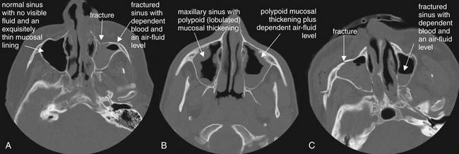
Figure 2-33 Sinus disease: Normal, air–fluid levels, and mucosal thickening.
Abnormalities of paranasal sinuses are commonly encountered on head or face computed tomography. A range of findings, from normal (A, right maxillary sinus), to mucosal thickening consistent with sinusitis (B), to traumatic blood with air–fluid levels (C, left maxillary sinus) may be seen. The clinical scenario plays an important role in determining the significance of imaging findings. In the absence of trauma, fluid may represent infection. With a history of trauma, fluid may indicate blood from a sinus fracture. Polypoid thickening is not the result of trauma and indicates preexisting sinus disease, whether infectious or allergic. In the absence of any clinical symptoms, sinus abnormalities may be incidental and may not require specific treatment. Controversy remains over the significance of mucosal thickening and air–fluid levels without fever, facial swelling, or purulent nasal discharge.
Mastoiditis
The mastoid air cells are air-filled spaces like other facial sinuses. The normal mastoid spaces are black, with a multitude of small cells created by fine bony partitions. Mastoiditis can be recognized on facial CT, although the field of view of facial CT often does not fully include the mastoid air cells. Like sinusitis, mastoiditis is characterized by fluid density (gray) replacing the normal air contents (black). Like sinusitis, mastoiditis can be complicated by intracranial extension and meningitis (Figure 2-34). Review the mastoid air cells on bone windows, because soft-tissue windows sometimes obscure the small mastoid air spaces. As with sinusitis, CT findings of fluid in mastoid air cells must be clinically correlated with signs and sympoms to determine their significance.
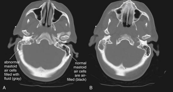
Figure 2-34 Mastoiditis resulting in meningitis.
Though technically not part of the face, the mastoid air cells share many common features with facial sinuses. The mastoid air cells are best viewed on bone windows, because soft-tissue windows often obscure the small air spaces. A normal mastoid is a spongy, air-filled lattice, and appears black on CT bone windows. Fluid in the mastoids is abnormal and appears gray on CT bone windows. In the seeting of trauma, fluid may indicate blood filling air cells from a temporal bone fracture. With no history of trauma, fluid should raise suspicion of infectious mastoiditis. Mastoid fluid can be recongnized on a noncontrast head CT and does not require special temporal bone view of facial series. This patient presented with confusion and nystagmus, as well as a history of right ear pain. A and B, Computed tomography (CT) showed opacification of the right mastoid air cells, consistent with mastoiditis. Given the patient’s confusion, meningitis as a complication of mastoiditis was suspected. Cerebrospinal fluid ultimately grew Streptococcus pneumoniae.
Evaluation of Facial Soft Tissues
Facial soft-tissue infections and masses can be evaluated well with CT with IV contrast. Neck infections are discussed separately in Chapter 4. IV contrast provides enhancement of inflamed tissues, abscesses, and neoplastic masses, as described earlier. Figure 2-35 demonstrates a CT scan of a patient presenting with significant facial swelling. CT confirmed parotitis, as well as surrounding cellulitis. Soft-tissue pathology is best viewed (no surprise) using soft-tissue windows. Axial views may be sufficient, although review of coronal views is prudent.
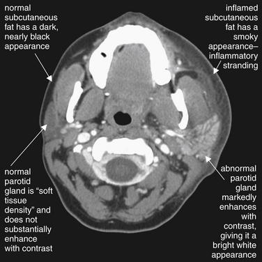
Figure 2-35 Parotitis with overlying cellulitis.
This 29-year-old female presented with 2 days of left face and neck swelling, tenderness, and erythema. CT of the face and neck was performed with administration of intravenous (IV) contrast. The image demonstrates enlargement and enhancement of the left parotid gland consistent with sialoadenitis. Compare the abnormal left parotid gland with the normal right parotid gland, which has nearly the same soft-tissue density as adjacent masseter muscle. The abnormal gland enhances due to increased blood flow and inflammatory vascular permeability. Soft-tissue swelling and stranding in the subcutaneous fat are also seen on the left side—again, compare to the normal right side. The CT demonstrated no drainable abscess, and the patient improved with IV antibiotics (clindamycin) alone.
Clinical Questions In imaging following facial trauma
Who Needs Facial Imaging? Does a Clinical Decision Rule Exist for Facial Trauma?
Facial fractures are common following blunt trauma. Approximately 12% of trauma patients requiring a head CT will have a facial fracture, and 50% of patients with one fracture will have multiple fractures.4 Well-derived and validated clinical decision rules for facial imaging do not exist. A number of small retrospective studies have evaluated physical examination findings, that might predict the presence of fractures. Lip laceration, intraoral laceration, periorbital contusion, subconjunctival hemorrhage, and nasal laceration were associated with facial fractures found on CT scan, and the study authors recommended that the presence of these findings be used to determine the need for facial CT.4-5 However, the weak associations identified in these studies mean that the presence or absence of these findings does not alter the pretest probability of injury to a degree that should drive our medical decision making. For example, extremity fractures were also statistically associated with facial fractures, but clearly the presence of an extremity fracture should not lead to facial CT in a patient without evidence of facial injury. A retrospective study published in the Journal of Trauma suggests that physical examination in alert patients detects most facial fractures (91.5%), and that radiographic findings altered management in a minority of patients. Unfortunately, methodologic flaws make this study unreliable. This was a retrospective chart review with no clearly described methods. It is uncertain how the researchers determined whether physical exam had revealed a fracture and, if so, what examination maneuvers or assessments allowed fractures to be recognized. The authors do not describe how they determined the role of diagnostic imaging findings in treatment decisions.6
What does this mean in practice? For the moment, the decision to perform facial imaging after trauma depends on your experienced assessment of the likelihood of a fracture, based on the aggregate of many factors, including the mechanism of injury, severity of exam findings, and the planned disposition of the patient. Can the patient receive follow-up if symptoms do not improve? Is a symptom debilitating (e.g., inability to open the mouth sufficiently to chew)? Your clinical gestalt will allow you to categorize the patient as high or low risk.
How Sensitive Is the Routine Noncontrast Head CT for Facial Fractures? If Head CT Is Performed for Evaluation of Intracranial Injury, Is a Dedicated Facial CT Required? Are Facial Reconstructions Required, or Is Review of the Axial Head CT Images Sufficient? Bottom Line: Does a Negative Head CT Rule Out Facial Fracture?
The sensitivity of routine noncontrast head CT to detect facial fractures is excellent when compared with dedicated facial CT, though occasional minimally or nondisplaced fractures may be missed if dedicated facial CT is not obtained (Table 2-3). Review of axial slices alone has a very high sensitivity, compared with additional review of coronal slices. For nonnasal midface fractures, one emergency department retrospective study found that axial noncontrast head CT at 10-mm slice thickness had a sensitivity of 90%, with a 95% confidence interval (CI) of 79% to 96%, and specificity of 95% (95% CI = 84%-95%).7 When coronal reconstructions are generated from axially acquired images using fine (1.25 mm) slice thickness, the sensitivity of CT is 97% for facial fractures, compared with coronally acquired images.1 Another retrospective study found that the sensitivity for facial fracture of routine noncontrast axial head CT images at 8-mm slice thickness was 100% when findings of an air–fluid level within the paranasal sinuses or fractures of the maxillary, orbital, or zygomatic bones were assessed. Facial fractures were ruled out by the absence of all of these findings.8
TABLE 2-3 Diagnostic Tests for Midface Nonnasal Fractures
| Sensitivity | Specificity | |
|---|---|---|
| Noncontrast head CT axial images | 90%–100% | 95% |
| Coronal reconstructions from axial facial CT | 97% | Not reported |
| True facial CT with axial and coronal reconstructions | 100%∗ | 100%∗ |
Does a Negative Facial CT Rule Out Intracranial Injury In a Patient with Facial Trauma?
We already reviewed studies suggesting that a normal head CT can rule out facial fracture. But the reverse is not true: a normal facial CT alone does not rule out intracranial injury, because the field of view of the scan is limited and does not include the entire brain and calvarium. Indications for head CT are reviewed in Chapter 1. If both brain and facial injuries must be ruled out, and if only one CT can be performed, head CT is the better choice to evaluate both brain and facial injuries.
Does Facial Trauma Predict Brain or Spine Injuries? If Facial CT Is Positive, Should Brain CT be Ordered?
The presence of some types of facial fractures increases the odds of concomitant skull base fracture and may be an indication for head CT. A single study found an increased risk of skull base fractures in patients with orbital rim and wall fractures, although this did not reach statistical significance. Orbital floor and maxillary and zygomatic arch fractures do not appear predictive of skull base fracture. Mandible and nasal fractures are rarely associated with skull base fractures. Increasing numbers of facial fractures increase the risk of coexisting skull base fracture—in one study, 21% of patients with one facial fracture had skull base fracture, whereas more than 30% of patients with two or three facial fractures had skull base fracture.9 Consider brain imaging if multiple facial fractures are present. As discussed in detail in Chapter 1, the Canadian CT Head Rule does not automatically require head CT for isolated blunt facial trauma unless findings of skull fracture, such as Battle’s sign, raccoon eyes, or cerebrospinal fluid otorrhea or rhinorrhea, are present.10 In contrast, the New Orleans Criteria (echoed in the American College of Emergency Physicians clinical policy for blunt head trauma) call for CT of the head when any “evidence of trauma above the clavicles” is present.11-12
How Does the Sensitivity of X-ray Compare to CT for Facial Fracture? Is there Still a Role for Plain Film in the Age of CT?
Facial x-rays have only moderate sensitivity as a screening test for midface fracture, based on limited studies. A systematic review performed in the Best Evidence Topics series found only five relevant studies to address this question.13 The reported sensitivity of facial x-rays for fractures ranged from 88.6% to 90.9%, although several of the studies had an inadequate or no gold standard, casting doubt on these numbers. One study investigated the sensitivity of a single OM15 view (occipitomental view, taken at 15 degrees), compared with the addition of an OM30 and lateral view. An OM15 x-ray had a sensitivity of 87.5%, with a specificity of 83%. The addition of an OM30 and lateral view increased the specificity to 97% but did not enhance sensitivity. The study authors point out a 50% reduction in use of x-ray and radiation exposures by use of a single OM15 view, omitting the lateral and OM30 views. However, this study was biased by a single reviewer who knew the study hypothesis and may have underestimated the additional yield of the OM30 and lateral views.14
Strangely, few studies have directly compared x-ray and CT. A study of 40 consecutive patients undergoing facial x-ray and CT showed the two methods to be equivalent for the diagnosis of zygomatic arch fractures, while CT was superior for orbital and maxillary fractures. This study has no independent gold standard, so the sensitivity of CT cannot be conclusively determined.15
A study in 1999 found that 70% of emergency department patients undergoing imaging for blunt facial trauma at Emory University in Atlanta, Georgia, underwent x-ray as the primary imaging study and 30% underwent primary CT. Patients undergoing primary facial CT were more likely to have at least one fracture detected (57% vs. 26%). This may reflect greater sensitivity of CT or selection bias, with patients judged by the emergency physician to be at high risk of fracture being chosen for CT first. Physicians may have opted to perform x-ray first in patients with low pretest probability of fracture. Of patients with a fracture detected on plain film, 29% underwent subsequent CT. Facial imaging charges are discussed later.
Is Diagnostic Imaging Required for Suspected Nasal Bone Fractures?
Treatment decisions for nasal bone fractures are typically based on the presence of external nasal deformity. The presence of nasal bone fractures correlates poorly with physical exam deformity. Consequently, nasal x-rays are unnecessary and not recommended for the evaluation of patients with nasal trauma.16 Despite this, a practice survey in England found that 57.9% of doctors in accident and emergency departments reported using nasal x-rays for a variety of reasons, including medicolegal, detection of unsuspected nasal fracture, compound nasal fracture, and foreign body detection.17 Surveys in Canada found similar rates of utilization, despite guidelines recommending against use of nasal x-rays.18 Introduction of a “no x-ray” policy for nasal bone fractures reduces unnecessary x-ray use.19 Given that CT scan is more costly than and involves a much higher radiation exposure than does x-ray, CT should never be ordered for the sole indication of evaluation of potential nasal bone fracture.
Is Panoramic X-Ray Better than CT for Mandibular Fractures?
Panorex has been the historical gold standard for the diagnosis of mandibular fractures. The technique allows projection of the curved structure of the mandible onto the plane of an x-ray film or digital detector, eliminating overlap of the mandibular rami, which renders standard anterior–posterior and lateral radiographs of the mandible difficult to interpret. CT scan is also useful in the diagnosis of mandibular fractures and has the advantage of being capable of diagnosing other traumatic injuries, including other facial, intracranial, and spinal injuries. Eliminating Panorex from the trauma workup could be valuable in the multitrauma patient, eliminating the need for the patient to be transported for additional diagnostic imaging when CT is already being employed for evaluation of other injuries. A recent study comparing Panorex and helical CT found that the two tests identify similar numbers of fractures. However, CT offered superior interobserver agreement on fracture number and location (96% for CT vs. 91% for Panorex). CT may be considered the new gold standard for radiographic evaluation of mandibular fractures, although Panorex is a reasonable alternative when other injuries to the head and face are not suspected.20 Panorex delivers about 8 mrem (8.0 × 10⁻⁵ Sv) and so carries a very low radiation exposure compared with facial CT, which has a dose of around 1 to 6 mSv depending on the exact CT protocol. Cancer risk depends on radiation dose, tissue sensitivity, and age at exposure. Radiation doses in the range seen with facial CT are predicted to induce cancers at a rate of 1 in 4000 to 1 in 15,000, while doses from Panorex, being about 100-fold lower, would be associated with an extremely low risk of cancer, 1 in 40,000 to 1 in 1,500,000.20a
When Should Orbital Imaging Be Performed for a Foreign Body? How Are Orbital Foreign Bodies Best Detected?
Globe injuries from penetrating foreign bodies represent an obvious high-risk injury due to risk of ocular infection, inflammation-mediated injury, and blindness. These injuries have a poor prognosis even when rapidly diagnosed. X-ray can detect small, high-density foreign bodies such as metal fragments with moderate sensitivity. In study of 204 patients with a suspected foreign body, only 70% of intraorbital foreign bodies were detected by x-ray, compared with 100% by CT.29 High-density orbital foreign bodies may be detected with high sensitivity on CT, but organic foreign bodies such as wood may be difficult to detect on CT or x-ray, because they have similar density to fat and air. MRI is more sensitive and should be used when an organic foreign body is suspected but not visualized on CT.23 Wood is sometimes visualized on orbital CT.30 Very-high-density materials such as metal can create streak artifact on CT, which may make determination of their exact size and location more difficult. Ultrasound is useful for evaluation of the globe but should be used with extreme care to evaluate suspected globe rupture, because pressure exerted during the ultrasound examination could result in herniation of globe contents.
If an Intraorbital Foreign Body Is Seen on X-Ray, Does CT Provide Useful Additional Information?
CT may be unnecessary when x-ray localizes a single intraorbital foreign body and if exam findings do not suggest ocular penetration. In addition, if exam findings are highly suggestive of ocular penetration and x-ray confirms a metallic foreign body, operative exploration is required and CT may play a limited role. If questions remain about addition radiolucent foreign bodies not seen on x-ray, CT may be useful.
Clinical questions in facial imaging When No History of Trauma Is Present
Facial imaging is often used to assess patients with nontraumatic pain, swelling, and erythema. The range of potential pathology is broad but generally may include infections, vascular abnormalities, and malignancies. CT is the most useful emergency department imaging modality in most cases, although ultrasound can be used to identify fluid collections. MRI is not usually ordered for this indication in the emergency department due to limited availability and long scan times. We review some of the more common clinical scenarios here, with CT findings demonstrated in the interpretation section earlier in this chapter.
When is CT Needed for Suspected Orbital Cellulitis?
CT is often used to distinguish orbital from periorbital cellulitis. As inflammation or frank abscess develops within the orbit, rising pressure may be exerted on the globe, optic nerve, and extraocular muscles. Increased pressure results in the classic exam findings of orbital cellulitis, which include proptosis, pain with eye movements, restriction of eye movements or frank ophthalmoplegia, diplopia, and change in vision with blurred or diminished visual acuity. The pupil may become unreactive as optic nerve compression increases. Periorbital erythema and edema alone are not suggestive of orbital cellulitis. No large high-quality studies have been conducted to determine the exam findings most predictive of postseptal (orbital) cellulitis. Multiple small retrospective studies have reported findings such as diplopia, ophthalmoplegia, and proptosis to be statistically associated with orbital cellulitis.21-24 A guideline published in Clinical Otolaryngology lists indications for CT, including neurologic abnormalities, inability to assess the eye due to gross periorbital edema, gross proptosis, ophthalmoplegia, abnormal pupillary response, worsening visual acuity or loss of color vision, bilateral eye involvement, failure to improve after 24 hours of therapy for periorbital cellulitis, and recurrent fever not resolved by 36 hours of therapy.25 The guideline authors recommend against CT unless one or more of these findings is present.
What Kind of CT Should Be Ordered for Orbital Cellulitis?
CT for detection of orbital cellulitis should be performed with IV contrast unless the patient has a contraindication (renal insufficiency or dye allergy). Generally, the CT should include both the orbits and the paranasal sinuses, as these are the source of infection in up to 90% of cases.21
What Are the CT Findings of Orbital Cellulitis?
The findings of orbital cellulitis are illustrated in the section on CT interpretation at the beginning of the chapter. What is the evidence for these findings? CT findings of orbital cellulitis include diffuse orbital fat infiltration (increased density or stranding) (seen in 24%), subperiosteal abscess (62%), and orbital abscess (13%).26 Orbital cellulitis can be a consequence of adjacent sinusitis or odontogenic infections, so the ethmoid and maxillary sinuses should be inspected for signs of sinusitis. The maxillary teeth should be inspected for periapical lucency suggesting dental abscess.27 Rarely, complications such as thrombosis of the superior ophthalmic vein may occur. CT with IV contrast can reveal this finding, and orbital MRI with gadolinium enhancement and fat suppression can further delineate this complication.28
Is CT Required for the Evaluation of Sinusitis?
CT is not routinely recommended for the diagnosis of sinus infections, unless complications such as orbital infection or intracranial extension are suspected. Guidelines published by the American Academy of Otolaryngology (Head and Neck Surgery) in 2007 support avoiding routine CT.31 The CT findings of bacterial sinusitis are relatively nonspecific, including air–fluid levels and mucosal thickening, which may be present in allergic or viral sinusitis. While these findings may be quite specific for bacterial infection in the setting of concurrent clinical findings such as facial swelling and erythema, facial pain, fever, and purulent nasal discharge, it is not clear that patient outcomes are changed by diagnostic CT in this scenario. Antibiotic therapy without CT may be appropriate, with guidelines suggesting that symptoms should be present for 10 days beyond the onset of upper respiratory symptoms. Multiple studies suggest that sinus abnormalities noted on CT in an asymptomatic patient (e.g., mucosal thickening and air–fluid levels in a patient undergoing head CT following head trauma) may not indicate acute sinus infection, as they occur incidentally in more than 40% of subjects.32-33 The Lund-MacKay scoring system evaluates sinus abnormalities on CT in a standardized fashion. Each of five sinuses (anterior ethmoid, posterior ethmoid, maxillary, frontal, and sphenoid) is scored on the following scale: 0 (no opacification), 1 (partial opacification), or 2 (complete opacification). The ostiomeatal complex is scored as 0 (not occluded) or 2 (occluded). The right and left sides are scored independently, for a total score ranging from 0 to 24. Using a Lund-MacKay score of 2 as the cutoff, sensitivity is 94% but specificity is only 41%, meaning that false positive outnumber true positives. At a Lund score of 4, specificity increase to 59%, but sensitivity falls to 85%.
Other authors contend that abnormal sinus CT results should not occur in normal, healthy patients. A retrospective study, they assessed three groups of patients: asymptomatic patients (defined as emergency department patients undergoing CT for indications presumably unrelated to sinus disease, such as syncope, alerted mental status, or stroke), acute headache patients (undergoing CT in the emergency department for assessment of acute headache), and chronically symptomatic patients (being evaluated in an otolaryngology clinic). Of asymptomatic patients, 3% had abnormal CT sinus findings, compared with 5.5% of acutely symptomatic patients and 64% of chronically symptomatic patients.36 The validity of these findings is questionable. This retrospective review identified patients by ICD9 ninth revision, code, and no additional clinical features were assessed. For example, although patients undergoing CT head for acute headache had a higher rate of sinus abnormalities, it is not clear that sinus disease was the cause of the patients’ acute headaches. Clinical guidelines require the presence of 10 days of symptoms for the diagnosis of acute bacterial sinusitis, and it is possible that the CT findings were actually incidental in patients presenting with headaches of other etiologies. The investigators did not review the charts for duration of symptoms or for fever, facial swelling, or nasal discharge. No confirmatory bacterial cultures were obtained in the asymptomatic or acutely symptomatic groups, so the contention that the sinus findings in the second group represent acute sinusitis is unconfirmed.
Are X-Rays Useful in Detection of Nasal Foreign Bodies?
X-rays for detection of nasal foreign bodies are likely to have a low yield. A study of pediatric patients presenting with suspected nasal foreign bodies or unilateral nasal discharge found that plastic beads, foam, paper and tissue fragments, and food matter accounted for 65% of foreign bodies—and none of these is likely to be identified on x-ray. In one small study, 7% of patients had a nasal button battery. The study’s authors recommended x-ray when a suspected foreign body is not visible on physical exam due to potential increased morbidity from prolonged presence of button batteries.37 CT can visualize nasal foreign bodies but may not be required—it may be more practical to examine the nose directly with nasopharyngoscopy or nasal speculum if doubts remain.
What is the Cost of Facial Imaging?
Facial CT scan is more costly than facial x-ray (Table 2-4).38 Arguments can be made for two strategies: facial bone x-ray first in low-risk patients (assessed clinically as unlikely to have fracture) and CT first in high-risk patients very likely to have fractures based on examination. In one study, patients undergoing facial x-ray as the first imaging test had an average imaging cost of $258, versus $1166 for patients undergoing CT first. If imaging costs are considered on a per-case-of-fracture basis (per patient having at least one facial fracture), an x-ray-first strategy cost $978, versus $2048 for a CT-first strategy. Clearly there is no role for facial x-ray in a patient considered to have very substantial risk of facial fracture, as CT would undoubtedly be performed following abnormal facial x-ray. More recent studies suggest facial CT alone has a cost of between $850 and $1450.1,5,8 Coronal reconstructions from head CT are somewhat cheaper, around $400 (in addition to the standard cost of head CT).1 Of course, economic evaluations are complicated by the number of different charges and costs that may occur in different practice settings. Medicare reimburses only about $214 for facial CT, so cost savings would be substantially less when using this figure for comparison.7 As discussed earlier, if a patient requires CT of the head for other clinical reasons, it may be reasonable to avoid any dedicated facial imaging and to review bone windows from axial head CT for fractures, with no additional cost.
TABLE 2-4 Hospital Charges for Facial Imaging∗
| Procedure | Cost |
|---|---|
| Orbital bone x-ray series | $76.23 |
| Facial bone x-ray series | $100.89 |
| Facial computed tomography | $722.70 |
| Coronal and sagittal reconstructions | $776.16 |
Adapted from Pearl WS. Facial imaging in an urban emergency department. Am J Emerg Med 17:235–237, 1999.
How Much Time Is Required for Facial Imaging?
Facial CT is very rapid with modern CT scanners, taking less than 1 minute. Facial CT is likely more rapid than facial x-ray for most patients.
How Much Radiation Exposure Occurs With Facial CT?
Radiation exposures from facial CT are significant, particularly because the field of view includes the lens of the eye and thyroid. In one study, dedicated axially and coronally acquired CT images of the face delivered 11.7 cGy to the orbit. Axially acquired images alone with reformatted coronal images deliver 6.7 cGy to the orbit.1 The ocular lens is susceptible to radiation-induced cataracts.39-44 The thyroid is susceptible to radiation-induced cancers, albeit at a very low rate, estimated to be between 4 and 65 per 1 million patients undergoing CT scan of the head.45 As a consequence, facial CT should be performed only when moderate suspicion for a clinically important condition exists. If CT is not performed, the patient can be counseled about the possibility of an undiagnosed injury and indications for follow-up.
Summary
CT is the most informative modality for facial imaging, with x-rays playing a limited screening role due to poor sensitivity. Indications for facial imaging have not undergone rigorous study, and clinical judgment will continue to play an important role in identifying patients requiring imaging. Because of the cost and radiation exposure from CT, emergency physicians should carefully consider whether CT findings are likely to change management before obtaining facial imaging.
1. Rosenthal E., Quint D.J., Johns M., et al. Diagnostic maxillofacial coronal images reformatted from helically acquired thin-section axial CT data. AJR Am J Roentgenol. 2000;175:1177-1181.
2. Le Fort R. [Experimental study on fractures of the upper jaw]. Rev Chir. 1901;23:208-227. 360-379, 479-507
3. Rhea J.T., Novelline R.A. How to simplify the CT diagnosis of Le Fort fractures. AJR Am J Roentgenol. 2005;184:1700-1705.
4. Holmgren E.P., Dierks E.J., Homer L.D., Potter B.E. Facial computed tomography use in trauma patients who require a head computed tomogram. J Oral Maxillofac Surg. 2004;62:913-918.
5. Holmgren E.P., Dierks E.J., Assael L.A., et al. Facial soft tissue injuries as an aid to ordering a combination head and facial computed tomography in trauma patients. J Oral Maxillofac Surg. 2005;63:651-654.
6. Thai K.N., Hummel R.P.III, Kitzmiller W.J., Luchette F.A. The role of computed tomographic scanning in the management of facial trauma. J Trauma. 1997;43:214-217. discussion 7-8
7. Marinaro J., Crandall C.S., Doezema D. Computed tomography of the head as a screening examination for facial fractures. Am J Emerg Med. 2007;25:616-619.
8. Lewandowski R.J., Rhodes C.A., McCarroll K., Hefner L. Role of routine nonenhanced head computed tomography scan in excluding orbital, maxillary, or zygomatic fractures secondary to blunt head trauma. Emerg Radiol. 2004;10:173-175.
9. Slupchynskyj O.S., Berkower A.S., Byrne D.W., Cayten C.G. Association of skull base and facial fractures. Laryngoscope. 1992;102:1247-1250.
10. Stiell I.G., Wells G.A., Vandemheen K., et al. The Canadian CT Head Rule for patients with minor head injury. Lancet. 2001;357:1391-1396.
11. Haydel M.J., Preston C.A., Mills T.J., et al. Indications for computed tomography in patients with minor head injury. N Engl J Med. 2000;343:100-105.
12. Jagoda A.S., Bazarian J.J., Bruns J.J.Jr., et al. Clinical policy: Neuroimaging and decisionmaking in adult mild traumatic brain injury in the acute setting. Ann Emerg Med. 2008;52:714-748.
13. Hogg K., Maloba M. Best evidence topic report: Which facial views for facial trauma? Emerg Med J. 2004;21:709-710.
14. Sidebottom A.J., Cornelius P., Allen P.E., et al. Routine post-traumatic radiographic screening of midfacial injuries: Is one view sufficient? Injury. 1996;27:311-313.
15. Tanrikulu R., Erol B. Comparison of computed tomography with conventional radiography for midfacial fractures. Dentomaxillofac Radiol. 2001;30:141-146.
16. Nigam A., Goni A., Benjamin A., Dasgupta A.R. The value of radiographs in the management of the fractured nose. Arch Emerg Med. 1993;10:293-297.
17. Oluwasanmi A.F., Pinto A.L. Management of nasal trauma: Widespread misuse of radiographs. Clin Perform Qual Health Care. 2000;8:83-85.
18. Li S., Papsin B., Brown D.H. Value of nasal radiographs in nasal trauma management. J Otolaryngol. 1996;25:162-164.
19. Sharp J.F., Denholm S. Routine X-rays in nasal trauma: The influence of audit on clinical practice. J R Soc Med. 1994;87:153-154.
20. Roth F.S., Kokoska M.S., Awwad E.E., et al. The identification of mandible fractures by helical computed tomography and panorex tomography. J Craniofac Surg. 2005;16:394-399.
20a. Smith-Bindman R., Lipson J., Marcus R., et al. Radiation dose associated with common computed tomography examinations and the associated lifetime attributable risk of cancer. Arch Intern Med. 2009;169(22):2078-2086.
21. Botting A.M., McIntosh D., Mahadevan M. Paediatric pre- and post-septal peri-orbital infections are different diseases: A retrospective review of 262 cases. Int J Pediatr Otorhinolaryngol. 2008;72:377-383.
22. Beech T., Robinson A., McDermott A.L., Sinha A. Paediatric periorbital cellulitis and its management. Rhinology. 2007;45:47-49.
23. Lakshmanan A., Bala S., Belfer K.F. Intraorbital organic foreign body: A diagnostic challenge. Orbit. 2008;27:131-133.
24. Ho C.F., Huang Y.C., Wang C.J., et al. Clinical analysis of computed tomography–staged orbital cellulitis in children. J Microbiol Immunol Infect. 2007;40:518-524.
25. Howe L., Jones N.S. Guidelines for the management of periorbital cellulitis/abscess. Clin Otolaryngol Allied Sci. 2004;29:725-728.
26. Pereira F.J., Velasco e Cruz A.A., Anselmo-Lima W.T., Elias J.Jr. Computed tomographic patterns of orbital cellulitis due to sinusitis. Arq Bras Oftalmol. 2006;69:513-518.
27. Caruso P.A., Watkins L.M., Suwansaard P., et al. Odontogenic orbital inflammation: Clinical and CT findings—Initial observations. Radiology. 2006;239:187-194.
28. Schmitt N.J., Beatty R.L., Kennerdell J.S. Superior ophthalmic vein thrombosis in a patient with dacryocystitis-induced orbital cellulitis. Ophthal Plast Reconstr Surg. 2005;21:387-389.
29. Saeed A., Cassidy L., Malone D.E., Beatty S. Plain X-ray and computed tomography of the orbit in cases and suspected cases of intraocular foreign body. Eye. 2008;22:1373-1377.
30. Karim A., Taha I., Tachfouti S., et al. [Intraorbital wood foreign body: A case study]. J Fr Ophtalmol. 2006;29:e29.
31. Rosenfeld R.M., Andes D., Bhattacharyya N., et al. Clinical practice guideline: Adult sinusitis. Otolaryngol Head Neck Surg. 2007;137:S1-31.
32. Havas T.E., Motbey J.A., Gullane P.J. Prevalence of incidental abnormalities on computed tomographic scans of the paranasal sinuses. Arch Otolaryngol Head Neck Surg. 1988;114:856-859.
33. Bolger W.E., Butzin C.A., Parsons D.S. Paranasal sinus bony anatomic variations and mucosal abnormalities: CT analysis for endoscopic sinus surgery. Laryngoscope. 1991;101:56-64.
34. Bhattacharyya N., Fried M.P. The accuracy of computed tomography in the diagnosis of chronic rhinosinusitis. Laryngoscope. 2003;113:125-129.
35. Bhattacharyya N., Jones D.T., Hill M., Shapiro N.L. The diagnostic accuracy of computed tomography in pediatric chronic rhinosinusitis. Arch Otolaryngol Head Neck Surg. 2004;130:1029-1032.
36. Wittkopf M.L., Beddow P.A., Russell P.T., et al. Revisiting the interpretation of positive sinus CT findings: A radiological and symptom-based review. Otolaryngol Head Neck Surg. 2009;140:306-311.
37. Glynn F., Amin M., Kinsella J. Nasal foreign bodies in children: Should they have a plain radiograph in the accident and emergency? Pediatr Emerg Care. 2008;24:217-218.
38. Pearl W.S. Facial imaging in an urban emergency department. Am J Emerg Med. 1999;17:235-237.
39. Grobe H., Sommer M., Koch A., et al. Dose reduction in computed tomography: The effect of eye and testicle shielding on radiation dose measured in patients with beryllium oxide-based optically stimulated luminescence dosimetry. Eur Radiol. 2008;19(5):1156-1160.
40. Heaney D.E., Norvill C.A. A comparison of reduction in CT dose through the use of gantry angulations or bismuth shields. Australas Phys Eng Sci Med. 2006;29:172-178.
41. Hein E., Rogalla P., Klingebiel R., Hamm B. Low-dose CT of the paranasal sinuses with eye lens protection: Effect on image quality and radiation dose. Eur Radiol. 2002;12:1693-1696.
42. Hopper K.D., Neuman J.D., King S.H., Kunselman A.R. Radioprotection to the eye during CT scanning. AJNR Am J Neuroradiol. 2001;22:1194-1198.
43. Ngaile J.E., Uiso C.B., Msaki P., Kazema R. Use of lead shields for radiation protection of superficial organs in patients undergoing head CT examinations. Radiat Prot Dosimetry. 2008;130:490-498.
44. Perisinakis K., Raissaki M., Theocharopoulos N., et al. Reduction of eye lens radiation dose by orbital bismuth shielding in pediatric patients undergoing CT of the head: A Monte Carlo study. Med Phys. 2005;32:1024-1030.
45. Mazonakis M., Tzedakis A., Damilakis J., Gourtsoyiannis N. Thyroid dose from common head and neck CT examinations in children: Is there an excess risk for thyroid cancer induction? Eur Radiol. 2007;17:1352-1357.